Haweswater Aqueduct, Hallbank Tunnel Replacement (2021)
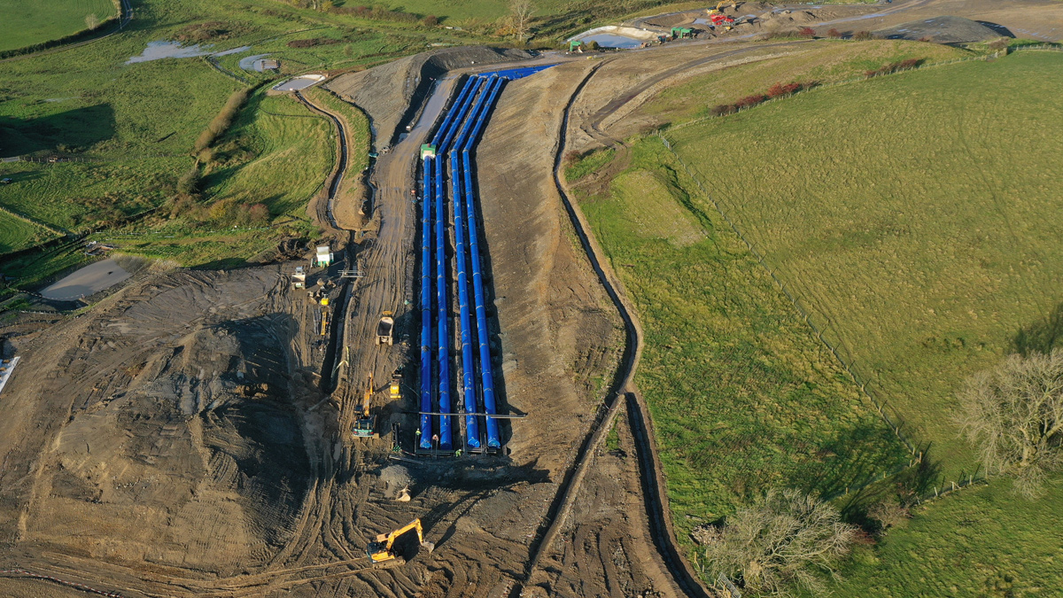
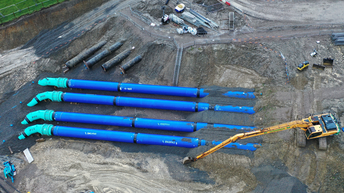
Four DN1600 steel pipes laid parallel – Courtesy of MMB
The Haweswater Aqueduct (HA) was constructed by the Manchester Water Corporation between 1935 and 1955 to provide water from Haweswater Reservoir to Heaton Park Reservoir in Manchester. The aqueduct was initially designed to convey 105 million gallons per day to allow for future increase in demand and is constructed of 8’ 6” concrete lined tunnels and covered concrete channels, 7’3” steel-cored concrete single-line siphons (SLS) and 48 – 54” steel multi-line siphons (MLS). The MLS were first constructed as two pipes, with provision made to increase to four lines as demand required. The capacity was increased with the construction of line 3 and line 4 in 1965 and 1977 respectively.
In 2013 and 2016 United Utilities (UU) undertook detailed surveys along the full length of the aqueduct. These surveys identified a need to increase resilience of the asset by replacing one of the tunnel sections. UU engaged Mott MacDonald Bentley (MMB) in summer 2018 as the AMP6 Construction Delivery Partner, to design, build and commission the replacement asset. The project achieved the target delivery date for project in use in October 2020.
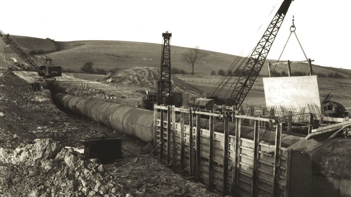
Construction of the existing aqueduct in the 1950s at the new connection site – Courtesy of United Utilities
Early contractor involvement & design
During a phase of early contractor involvement (ECI), initial collaborative optioneering between UU and MMB determined the optimum solution, bringing cost certainty and reduced programme risk. This solution comprised the extension of the existing four-line siphon in the north through four new DN1600 pipelines, each 2.5km in length, ultimately converging into the existing single line siphon in the south through a manifold structure. In addition, it was recognised that early supply chain engagement would be critical to successful delivery of the project.
The original scope considered construction of connections to the existing aqueduct during an initial shutdown with a final connection and switching of flows during a second outage. Collaborative optioneering determined that the new pipelines could be constructed ‘offline’, allowing connections to be made in a single, time limited outage. This generated significant cost savings and overall risk reduction.
Early surveys
To inform the overall design, early surveys including topographical, environmental and ground investigation were undertaken. This allowed key project risks to be fully accounted for during initial scheme design. The pipe route took account of the sensitivity of local stakeholders and crossed largely pastural land, including organic fields, watercourses and roads. The drumlin hills of Cumbria further presented challenging topography for the construction of the pipelines.
Detailed assessment of prevailing ground conditions allowed engineers to have confidence that dug materials could be suitably processed on site to generate fully compliant pipe bedding and surround. This brought distinct efficiencies including reduced material import and pipe wall thickness requirements.
Detailed design
The original ECI scope considered first constructing the connections during an outage window, with flows returned during the construction of the new asset before a final switching of flows during a second outage. During the ECI stage, the team recommended first constructing the new pipeline ‘offline’, allowing connections to be made in a single, time limited outage.
The preferred solution consisted of 4 (No.) individual steel pipelines of 1600mm internal diameter, each 2.5km long and connecting to the existing MLS at the upstream end of the works, and transitioning to a SLS through a manifold arrangement at the downstream end of the works. The pipelines were constructed over a two-year programme from contract award to water into supply, with the final connection during a regional demand governed shutdown in October 2020.
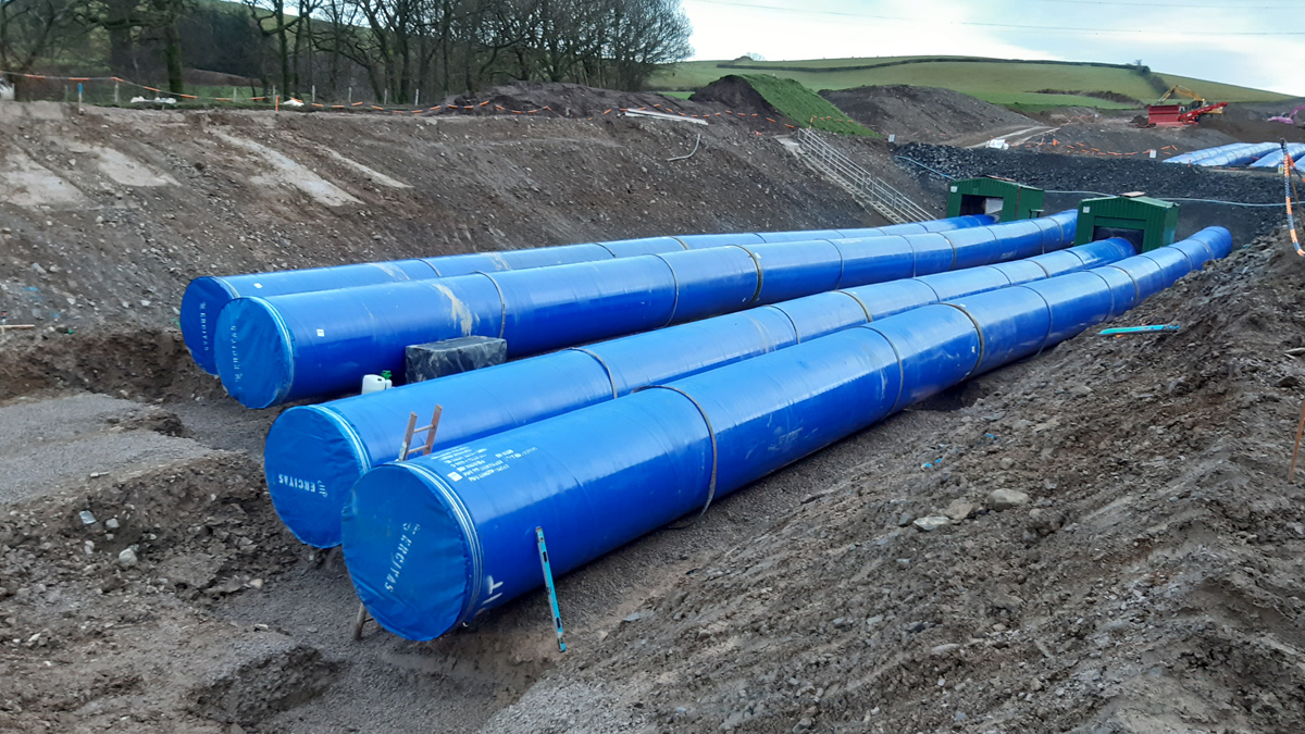
Using deflection along the joints facilitated removal of dedicated fittings – Courtesy of MMB
Detailed design balanced the physical properties of site won materials, adopted as bedding and surround, against the structural design requirements for the pipe. An optimum ratio of pipe diameter to wall thickness of 128 was achieved, resulting in a 12.5mm wall thickness. Optimising the wall thickness over a combined pipeline length of 10km brought significant cost, environmental and carbon reduction benefits to the project.
MMB engaged with supply chain partner FT Pipeline Systems to supply over eight hundred 14m steel pipes with a three-layer PE external coating and Drinking Water Inspectorate approved internal coating with a minimum dry film thickness of 500 microns. FT Pipeline Systems also supplied almost 100 bespoke fittings for tees and bends. Each pipe adopted the proprietary e-joint socket and spigot system, with external circumferential welding to each joint, removing the need for internal welding.
The new pipeline can transfer over 520ML of water per day. To support future maintenance operations, the pipe diameter was defined to provide over 90% of the required flow through three of the four new pipelines.
Design efficiencies
The project critical path was through the welding programme. To minimise the number of joints, Engineers maximised individual pipe lengths and adopted design for manufacture and assembly (DfMA) principles by combining bend angles into air valve and washout tees to provide dedicated fittings. This approach, together with a defined flexibility in bend position, maintained pipe wastage below 3%.
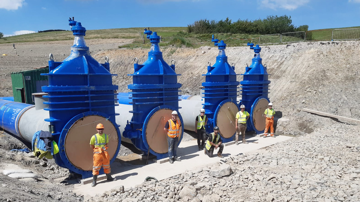
4.5m tall DN1600 gate valves, weighing in excess of 10 tonnes each, installed upstream of the new manifold arrangement – Courtesy of MMB
Haweswater Aqueduct, Hallbank Tunnel Replacement: Supply chain – key participants
- Construction delivery partner: MMB
- Pipelines (south): Waitings Ltd
- Geotechnical investigation: Geotechnics Ltd
- Welding: Environmental Fabrications Ltd
- Welding inspection: Symthy Consultants
- Environmental clerk of works: Emerald Green Environmental Management Services Ltd
- Ultrasonic surveying techniques: Advanced Engineering Solutions (AESL)
- Demolition: S Evans & Sons
- Wire saw cutting: Holemasters
- Pressure & turbidity instrumentation: ATI UK
- Pressure & flow instrumentation: Flowcheck
Surveying: Day Civils - Pipelines & pipe fittings: FT Pipeline Systems
- Canusa pipe coating: FT Pipeline Systems
- Connection large diameter pipe fittings: Freeflow Pipe Systems
- Valves: AVK UK Ltd
- Valves: Glenfield Invicta
- Aggregates: L&W Wilson
- Concrete: Hanson UK
- Concrete: Breedon Group
- Small diameter pipe fittings: Saint Gobain PAM UK
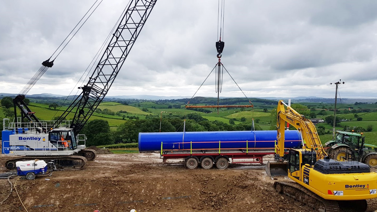
A 14m length of DN1600 pipe being lifted into position by the 80T crane – Courtesy of MMB
Pipelaying
The pipelines were constructed over a two-year programme from contract award to water into supply, with the final connection during an aqueduct shutdown in October 2020.
To achieve the challenging programme, pipelaying was completed on two work fronts from the middle outwards with MMB laying northward and subcontractor, Waitings Ltd, laying southward. This introduced a spirit of healthy competition between construction gangs on site. The pipes were laid simultaneously by traditional open cut methods with backfilling following closely behind. As the alignment followed an existing hillside, the vertical alignment was rationalised by stepping the excavation by up to 1.2m between the centre two lines, reducing the overall excavation volume.
Intelligent compaction plant was used for pipeline backfill and surround re-compaction. Compaction equipment with integral compaction indicator systems were calibrated against the minimum design requirements through early compaction trials. As a result, the overall duration for compaction activities was reduced when compared with industry standard ‘method’ compaction techniques whilst still maintaining assurance of construction quality and specification compliance.
Pipe jointing was achieved by metal inert gas (MIG) welding across the external annulus of the e-joint. Each weld was inspected using magnetic particle inspection (MPI) testing and all joints received an external coating using Canusa K-60.
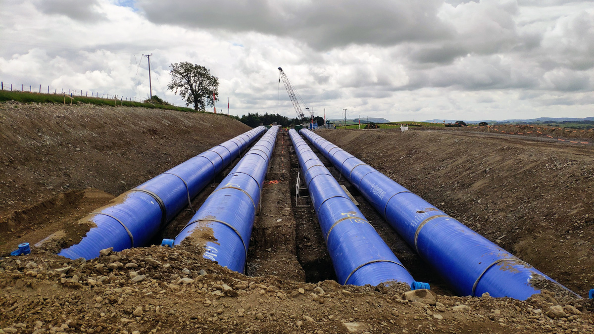
The excavation was stepped across the easement to reduce earthworks – Courtesy of MMB
Detailed temporary excavation design
The scale of excavation required to accommodate four parallel DN1600 pipes drove a considered approach to earthwork design. As previously discussed, the pipe specification considered the re-use of excavated material for backfill to minimise imported material. As such a detailed material grading specification was developed based on the ground investigation data.
Further to the stepped excavation profile, the overall volume of excavated material was reduced by value engineering the earthworks design. Initial design development had assumed a temporary excavation batter of 1:2.5. Through detailed geotechnical design the temporary excavation batter angle was reduced to between 1:1.6 and 1:1.8, reducing the overall excavation volume by almost 20% with benefits including; increased excavation progress rates, reduced programme risks, reduced reinstatement works and reduced carbon footprint.

The excavation profile developed during design to consider the extensive earthworks required – Courtesy of MMB
Digital delivery efficiencies
All excavation was completed using GPS enabled plant to accurately form the excavation profile. Design delivery consisted of the 3D model being uploaded into the GPS plant and robotic total station. This reduced overall traditional setting out requirements for site engineers and ensured that plant operators could not over excavate or exceed safe earthwork batter angles.
To improve overall project efficiency and maintain high quality construction records, working with UU, the project adopted Survey123 from ArcGIS to record and analyse all quality records. The system allowed real-time data collection for validation and geo-tagging of construction records to map progress along the route via a shared dashboard. A fully digitised collection of construction quality and as built data as works progressed, allowed efficient asset handover to UU within hours of connection completion, as opposed to more traditional approaches often taking many months.
Pressure testing & commissioning
Pipelaying, welding and backfill was completed ahead of schedule in May 2020. The water loss method of pressure testing was used under IGN 4-01-03. Each line was independently tested over the full 2.5km length between the connection locations, requiring over 5ML of water per line. All four pressure tests presented a first-time pass, accredited to the ongoing quality management of both welded and flanged connections.
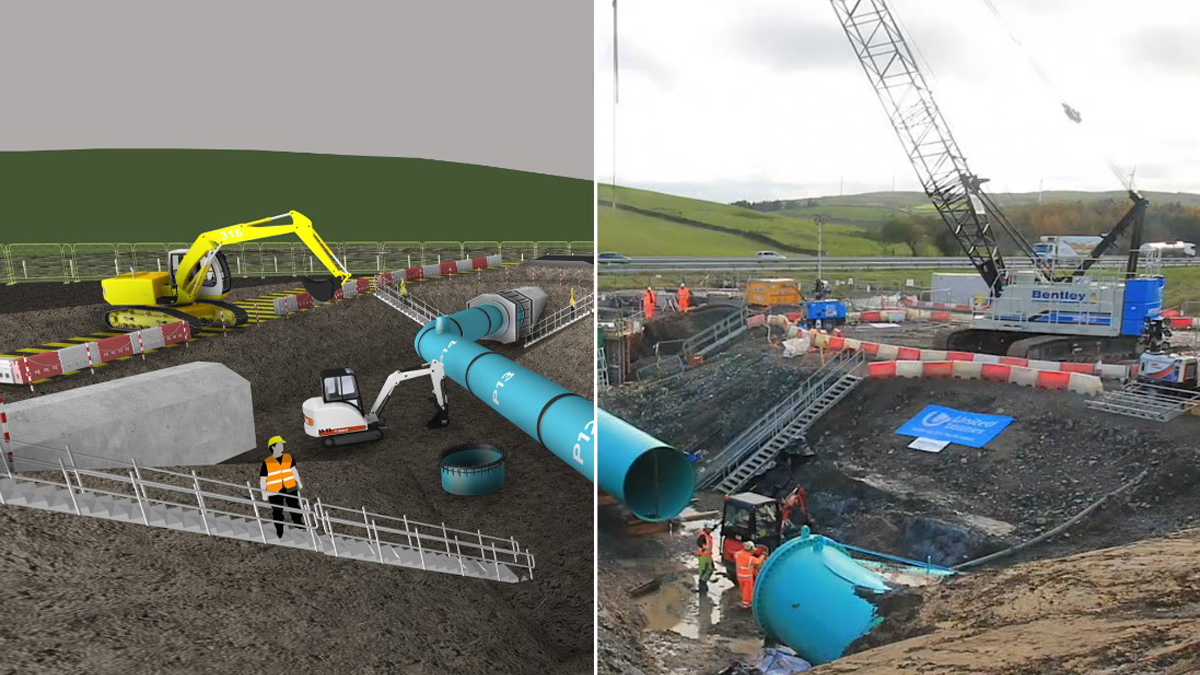
The 4D model allowed full digital rehearsal of the connection, including temporary works – Courtesy of Freeform 4D
Critical outage connections – Preparation & optimisation
The connections required isolation of the HA through a total shutdown, itself a huge undertaking for UU to maintain regional supplies.
To minimise the outage duration, the off-line pipeline was constructed as close as possible to the existing, including the completion of the complex manifold arrangement to the south. The connection design reduced time on site by reducing the number of joints and maximising laying sequence. Connection to the existing HA was completed by flanged and welded steel pipework supplied by Freeflow Pipesystems.
Working 24/7 allowed removal of redundant pipework and connection of the new pipework to be completed in under 8 days: a significant decrease from the maximum 28 days available.
To help ensure the success of the connection within the agreed timescales, the 3D model was combined with the outline programme to create a 4D model (Level 2 BIM). The model was used to identify opportunities in sequencing and arrangement by allocating plant and labour to each programme item. By linking the model to the programme before design freeze, the arrangement of fittings, pipe lengths and lay sequence could be modified to reduce time on site. By modelling the full extent of temporary works, including the excavation profile and the lifting capabilities of plant, end-to-end digital rehearsal allowed repeated optimisation of the shutdown.
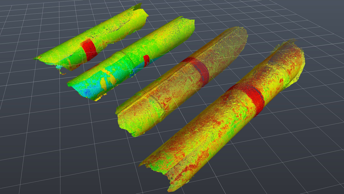
A point cloud of the existing aqueduct confirmed the existing gradient, position and dimensions – Courtesy of MMB
North connection – four lines into four lines
The existing MLS comprises bitumen coated and lined steel pipes with alternating diameters of 48”/54”/48”/54”. The existing steel pipes were surveyed prior to the connection window to confirm steel grade and thickness, alongside laser scanning to validate position, gradient and overall dimensions. The point cloud survey was used within the federated model and by the connection pipework manufacturer to create precise fittings for an optimum connection arrangement.
The connection location presented challenging topography at a 1:14 gradient. Laser scan surveys confirmed that the four existing lines differed in elevation and gradient at the same chainage.
The connection pipework was modelled by pipework manufacturer Freeflow Pipesystems, with bends and tapers accommodated in a single piece to reduce onsite connections. Connection to the existing pipelines used continuously welded socket spigot pipes and flange adaptors to connect to the new pipelines.
Connections to the new aqueduct completed during an 8-day outage – Courtesy of MMB
South connection – four lines into one
The existing SLS was constructed of a 7’6” ID steel core with concrete surround. This form of construction allowed only non-intrusive investigation prior to the outage. Advanced Engineering Solutions (AESL) provided ultrasonic surveying techniques to determine the thickness and density of the existing concrete surround and the position of the steel core. The concrete surround was surveyed and used in the federated model to provide the position and gradient for the existing pipe.
In the absence of validated as-built details, the connection design incorporated a flat plate steel face to abut the existing steel core and allow flexibility for ovality, position and diameter. Further flexibility was offered by the socket spigot joints in the approaching pipework.
The connection location was cut using a wire saw and redundant pipework removed. The existing concrete surround was removed by hydro demolition to expose the steel core which was found to be in remarkable condition considering its age. Metallurgy testing was undertaken to ensure compliant welding was available before the new flat steel face was offered to suit.
The new pipework was internally welded to the existing steel core and externally surrounded with a reinforced concrete collar and saddle to the approaching pipework.
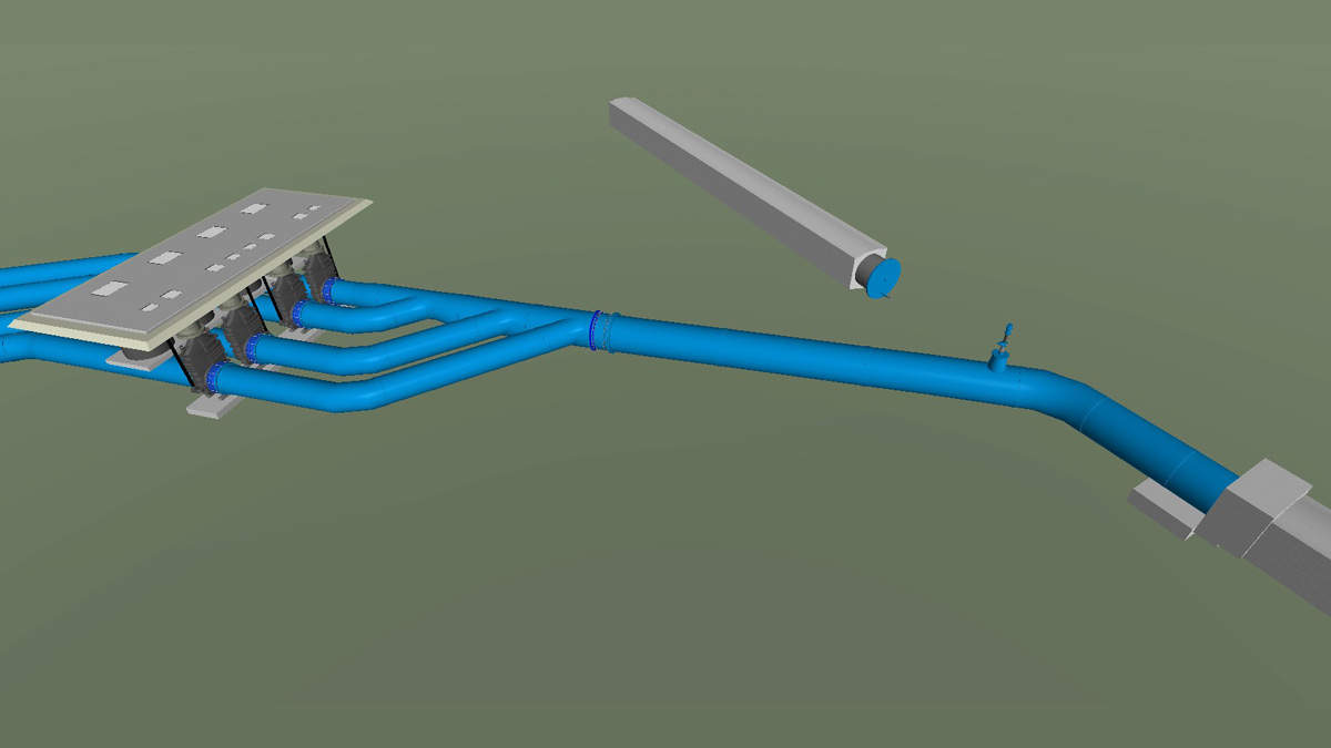
The 4 (No.) DN1600 pipes converge to a single 2200mm pipe before connection to the existing aqueduct – Courtesy of MMB
Summary
The design for construction and commissioning approach allowed repeated efficiencies by removing on site works and minimising critical time-constrained activities. The collaborative approach between MMB and UU harnessed the principles of “one-team with a common goal” and was instrumental to project success.
Establishing the golden thread of information through design, construction and commissioning provided a seamless handover to the operational owners for a quick and successful return to service. The use of digital delivery through laser scanning, 4D modelling and digital quality assurance significantly aided the collaborative approach to successful delivery.
The replacement of this tunnel section of the HA is the first of the wider HA Resilience Programme (HARP) to increase resilience of one of the regions critical water supplies.


