Ashford WwTW Sludge Treatment Centre (2018)

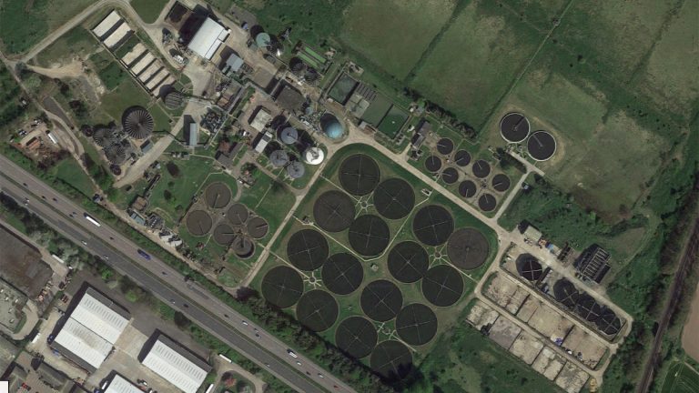
Existing plant - Ashford WwTW/STC - Courtesy of BTU
Ashford Wastewater Treatment Works is located in Kent alongside the M20 motorway, near the River Great Stour to the South of the Kent Downs (Area of Natural Beauty). The Town of Ashford has a population of approximately 110,000 people. The WwTW serves Ashford and surrounding areas and is supplied by five local pumping stations taking in indigenous wastewater, sewage, and imported sludge/cake from wastewater treatment works all over Kent.
Background
The original filtration system at Ashford WwTW for removing siloxane required regular planned maintenance to replace the media and service parts of the process, frequently rendering the system unavailable and raised concerns as to the efficient running of the plant.
Southern Water decided to trial an activated carbon system at three regional sludge treatment centres (STCs). These filters retain up to 90% of the siloxanes from the biogas. At present Southern Water has sixteen STCs across the region, of which nine had the new activated carbon filters installed. Ashford was the next site on the programme.

Ashford WwTW – Courtesy of Southern Water
The driver
Whilst effectively treating the sewage process, anaerobic digestion generates a high grade of gaseous fuel, also known as sewage gas, a renewable energy source, which can be utilised for the generation of electricity. With this process and through a biogas engine (CHP unit), the sewage treatment plant meets its target carbon footprint.
As sludge undergoes anaerobic digestion, it may be subjected to temperatures up to 60°C. At this point the siloxanes contained in the sludge will volatise and become an unwanted constituent of the resulting biogas. This problem can be exacerbated by the fact that silicones-based anti-foaming agents are frequently added to the digesters; these silicones sometimes biodegrade into siloxanes. Unfortunately, when siloxanes gasses are burned, they are usually converted into silicon dioxide particles, which are chemically and physically similar to sand. Siloxanes can also be a problem with biogas used for fuel cells.
During the combustion process the volatile methyl siloxanes (VMS) converts into silicates and when combined with the engine oil, form into a hard ash like compound, which can cause damage to engine parts (valves, pistons etc). To remove these harmful siloxanes a siloxane filtration system is utilised.

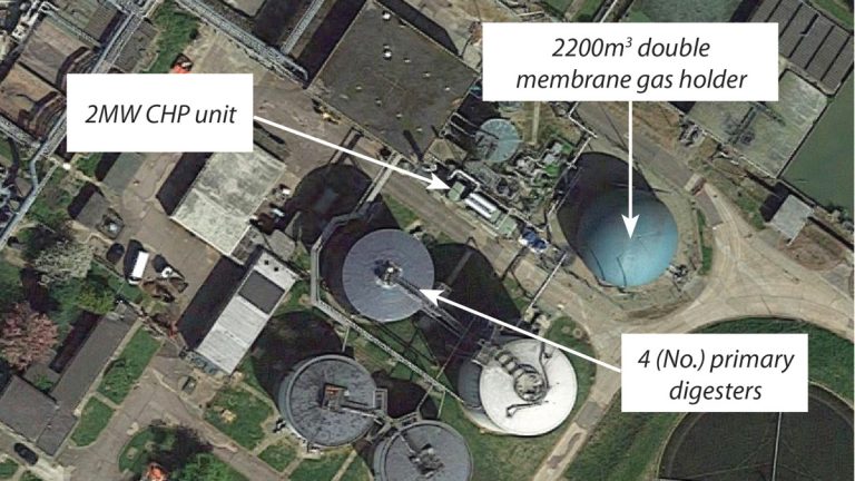
Ashford STC – Existing gas area layout – Courtesy of BTU
Impact
This method of filtration ensured that Southern Water would contribute with regards to optimisation and see a positive benefit towards revenue expenditure. The utilisation of the newly installed siloxane carbon filtration units would also:
- Increase power generation efficiencies, reduce system downtime due to maintenance and improve operational capability.
- Ensure that Southern Water’s revenue is optimised due to better generation of power, and a less onerous maintenance regime.
Scope of works
Southern Water’s brief included:
- Remove existing siloxane removal filter system.
- Install a new concrete slab and create access to the gas holder compound.
- Installation of carbon filters for the biogas plant with a standby connection to facilitate changeovers.
- Run a new stainless-steel gas supply from the existing biogas boosters to 2 (No.) new 4m3 carbon filters incorporating the existing Kelburn filter.
- Connection to the existing CHP supply.
The proposal
A site survey was conducted to ascertain the most effective location that was suitable for the new carbon filters. From the survey a suitable area inside the biogas holding compound was selected with Southern Water’s approval. The main advantages for this placement was due to having restricted access and due to the local positioning to nearby condenser removal points and CHP unit.

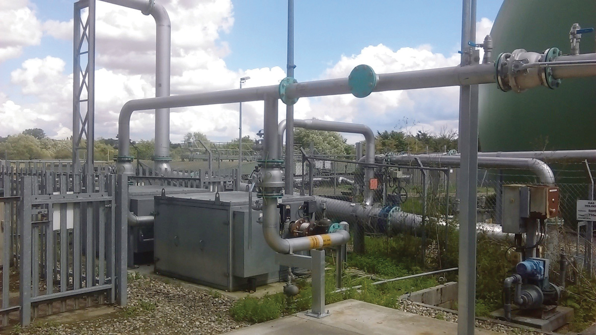
(left) Existing siloxane removal system and (middle) fence construction prior to filter installation and (right) view of selected gas holder compound – Courtesy of BTU
Pre-construction
The existing site needed to stay in operation during the new installation works so it was necessary to keep a small footprint to ensure not only workforce safety, but for the operations teams on site. All material removals off site had to be coordinated and a traffic plan put in place to ensure normal routine and operations could be maintained.
Civils proposal
A new reinforced concrete foundation was installed to one corner of the existing compound. The foundation construction was 5m x 3m with a base depth of 800mm, 300mm AGL. This would be offset 100mm from the existing fence line of the two faces of the corner. The road facing section of the chain link fence was to be replaced with a wide double gate, positioned suitably to allow for the removal of the new tanks. Positioning of the tanks via Hiab lorry had to be positioned on the adjacent hardstanding.
Electrical proposal
The electrical control panel was located within the area of the redundant equipment, isolated and made safe with a potential for future use. The incoming power cables were traced back and isolated from the main MCC, leaving the panel free from power.
Mechanical proposal
On completion of the new 5m x 3m concrete base for the new carbon filters BTU then installed two new 2m wide gates in front of filters to allow for the removal from the compound. We then Installed a handrail around the edge of the concrete base inside the compound.
A new 150mm piped supply which included the new Pekos stainless steel ball valves connecting from the existing gas boosters, to the existing gas supply to Kelburn filter unit was installed. Purging and test points were also provided either side of new valves. From the Kelburn filter 200mm supply to the carbon filters was installed, terminating at the agreed valve arrangement for the carbon filters which comprised of eight 200mm Pekos stainless steel ball valves and test and purge points on the inlet and outlet of carbon filters. The valve arrangement was designed to allow either carbon filter to run as the lead tank or lag tank.
A 200mm supply from the outlet of the valve arrangement to the existing supply to the CHP was then incorporated. Installation of 3 (No.) Spirax Sarco float valves and condense lines, two for the gas booster low points and one just before the filters was fitted. The Purge and test system was then put into service. With final removal all redundant equipment ensuring all equipment where made electrically safe.
Efficiency
The holistic review of the scope of works and subsequent approved solution had identified the most cost-effective method regarding economical running of the plant, and the least risk delivery solution ensuring the solution met both compliance and the technical standards, to which the project was governed.
Carbon filter tank specification
CC Jenson Ltd were contracted to scope, identify, and specify the design for the carbon filter tanks and 2 (No.) VOC 4m3 HFAB-200 tanks filled with ACR64 carbon were specified. The tanks were constructed of fully welded carbon steel and mounted on a steel skid. Each tank had a clean empty weight of 1215kg and full weight of 3135kg. Their pressure was rated at a minimum of +500mb/-5mb with a maximum pressure drop of 3.5mb. Each tank had to have a gas flow of 884m3/hr.
All drain and purge points were stainless steel lockable ball valves with plugs. Inlet and outlet pipework (DN 316 stainless steel) was OD of 200mm comprising of PN16 flanges. The tanks were pre-fabricated with 2 (No.) 200mm x 100mm x 5mm RHS fork truck skids. The mounting frame was fabricated from 150 x 100 PFC (3200mm x 2020mm) fitted with a 1” frame drain and four corner lifting lugs; the frame was bolted down with 16mm frame fixing bolts.

(left) Concrete base construction and (right) carbon filter installation – Courtesy of BTU
Construction
Throughout construction the existing plant had to be operational to enable the CHP to continue generating power and providing heat for the process. Careful planning was needed because of the location of the new slab and the location of carbon filters in the corner of the double membrane gas holder compound. Due to this location, gas monitors were worn by all operatives and shielding was utilised to prevent damage to the gas holder.
The programme of works meant that the new base and gates were first to be installed. This was the enabling priority to allow for the delivery and installation of the carbon filters, with the new tanks and associated pipework next to be installed. Pipe supports were installed in approved locations to allow for a one-day shutdown of the plant to enable the pipework to be tied in at the correct points.
For the shutdown/tie-in day the secondary form of sludge heating was utilised; 2 (No.) dual fuel boilers running on biogas/light oil. The boilers were test fired prior to the shutdown to make sure compliance was met.
The existing biogas pipework was isolated, and nitrogen purged out of service. The new pipework was connected to the new tanks and to the existing gas boosters and Kelburn filter. All the pipework and tanks were then tested and purged back into service. All testing and purging was carried out in accordance with the Gas Safety (installation and use) Regulations (GSIUR) and IGE/UP/1A.
Once tested and purged the CHP was put through a commissioning programme to ensure it met all operational needs for the client. Once accepted into operation, BTU decommissioned the original plant, which was removed off site and disposed of accordingly.
Conclusion
To ensure that the works were carried out diligently, professionally, and safely, Elizabeth Yates, BTU’s Project Manager, worked closely with the design team, site team members and operations staff. Pipework, filters and associated valve arrangements were positioned, calculated, and risk-designed to ensure efficient running of the newly installed plant including the planned maintenance regime associated with this equipment.


