
Beckton STW (2023)
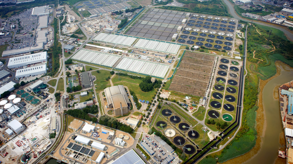
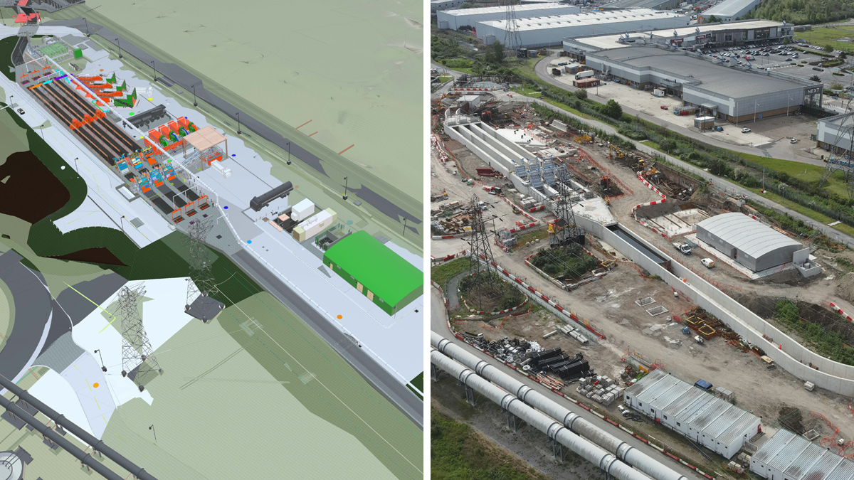
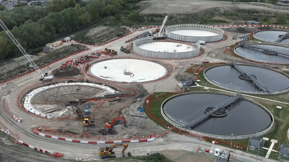
Aerial view of Beckton STW before the AMP7 project started - Courtesy of Thames Water
Beckton Sewage Treatment Works (STW) is the United Kingdom’s largest STW serving a population equivalent of over four million. The AMP7 project is a major £185m investment to increase the site’s treatment capacity for growth, by a population equivalent of 200,000, by extending the existing activated sludge plant (ASP). Beckton STW will receive stormwater from the Thames Tideway Tunnel ‘Super Sewer’ when it is commissioned in 2024. The project will improve resilience of the inlet works by providing more screening and grit removal plant to increase redundancy, the improvements will deliver on a Regulatory Performance Commitment. The project also includes elements of capital maintenance; mainly on electrical infrastructure and sludge treatment, to ensure resilience and effluent quality is maintained.
The existing plant
The first works at Beckton was built in 1864 by Sir Joseph Bazalgette as part of the revolutionary Victorian sewer network, which drastically improved water quality in the River Thames. The plant has since been extended numerous times and covers over 100 hectares (250 acres). Sewage is received from a large collection of sewers and pumping stations, which all connect to the Northern Outfall Sewer (NOS) that comprises five large brick barrels. Beckton’s flow to full treatment is 27m3/s, with peak storm flow of 32m3/s.
The preliminary treatment is by coarse and fine screens, with grit removal located between the screens. Primary treatment is by two banks of rectangular primary settlement tanks (PSTs), each consisting of eight PSTs. The secondary treatment is by a conventional activated sludge process with three separate streams ranging in age, numbered ASP2, ASP3 and ASP4. Each of the ASPs include a set of final settlement tanks (FSTs). Final effluent is discharged to a common channel that leads to the main outfall to the River Thames, upstream of the Barking Creek Barrier.
Sludge is treated through a process of anaerobic digestion and thermal hydrolysis. Biogas is captured from the digestion process and generates electricity and heat through combined heat and power engines (CHP). Beckton can produce half of the required electricity to run the treatment process from the CHP engines, and an on-site wind turbine. Digested cake is exported from the site to agriculture and there is an option to process the sludge in the sludge powered generator that also provides electricity for the site.
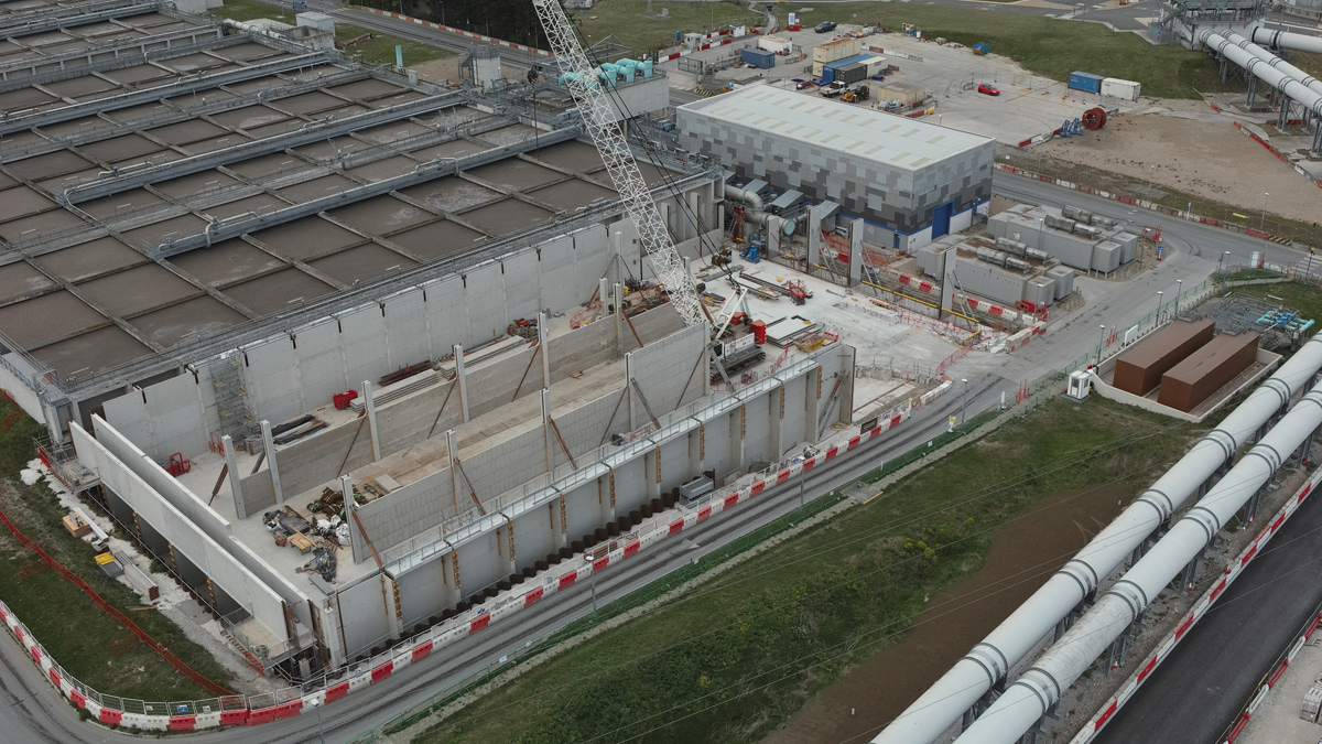
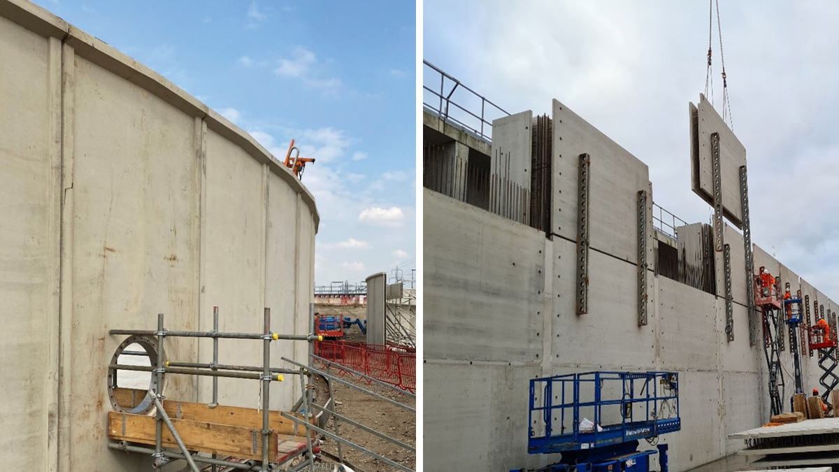
ASP4 South Tank twin wall under construction – Courtesy of Laing O’Rourke
What’s being provided?
Thames Water has appointed Laing O’Rourke to deliver the project, with multidisciplinary design services being provided by Atkins (SNC Lavalin). The contract was awarded in July 2020, with construction works starting in April 2021 and the works will be completed and handed over in phases throughout 2024.
New and existing inlet works
A new inlet works will be constructed comprising three lanes that contain coarse (50mm) and medium screens (20mm) provided by Huber Technology, and grit removal plant. One of the existing inlet works lanes will be sacrificed to provide the feed to the new lanes, hence the provision of two additional lanes in terms of redundancy. The constant velocity grit channels have a capacity up to 15m3/s with SAVECO Environmental Ltd supplying traditional grit bridges with an alternative method of grit suction. The associated instrumentation is from Vega Controls Ltd and the automation and control panels for the grit bridges has been designed and built by Te-Tech Process Solutions.
Grit classifiers with combined output of up to 88 tonnes/hour and launder channels in this process stream are being supplied by FLSmidth, and Fluid Sealing & Engineering (FSE) Ltd respectively.
The process streams for screening and grit removal along with the associated handling plant for the new inlet works follow a similar arrangement to the existing inlet works. The existing inlet works will be supplemented with medium screens, supplied by Huber Technology, in the remaining five lanes to reduce the load passed forward to the fine screens and to improve the reliability of the existing grit removal plant.
A significant upgrade to the electrical infrastructure is required with a large glass reinforced plastic switchroom supplied by Morgan Marine. Winder Power Group are supplying the transformer and electrical installation has been subcontracted to AVRS Systems. The new switchroom houses the new high voltage (HV) and low voltage (LV) electrical panels, provided by Siemens and Total Automation & Power (TAP) respectively, supplemented by a new diesel operated generator to improve resilience.
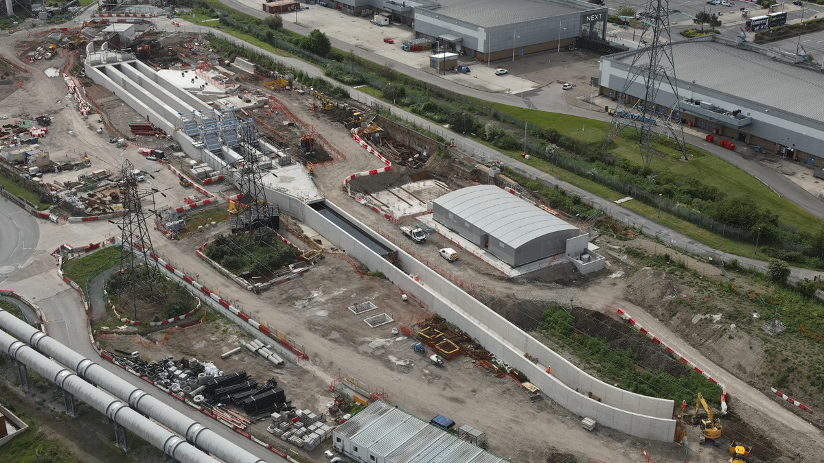
New inlet works under construction – Courtesy of Laing O’Rourke
ASP4 extension and sludge improvements
ASP4 was installed under the last major upgrade at Beckton (by Laing O’Rourke), which completed in 2014 and currently treats up to 8m3/s. This project will provide two new aeration lates in separate tanks, referred to as the North and South Tank. Each are 85m long, 41m wide and 8.5m deep. Four new FSTs will be provided; each being 45m diameter and 5m deep.
A new aeration building is required to house blowers for the new aeration lanes with the aluminium clad structural steel building envelope installed by Galloway Construction Ltd. The aeration blowers are supplied by Howden, diffusers by Xylem Water Solutions and new transformers by Winder Power Group as part of a substantial upgrade to the existing electrical infrastructure for the new ASP.
The sludge improvements include new Huber Technology raw sludge screens to remove rags and improve resilience in the sludge treatment stream. Sludge treatment capacity improvements, surplus activated sludge (SAS) thickening, is by new gravity belt thickeners (GBTs), supplied by Kent Stainless Ltd in a new building. An extension to the existing sludge cake barn building to increase sludge cake storage capacity is required. The sludge steam has further resilience work by the provision of a polymer dosing facility, new electrical infrastructure, new sludge holding tanks from Stortec Engineering Ltd, and an upgrade to existing tanks.
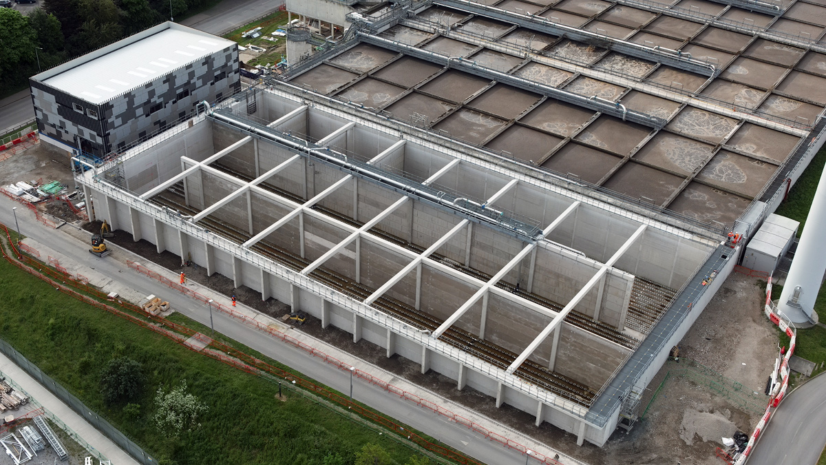
ASP4 North Tank completed and new blower building cladding underway – Courtesy of Laing O’Rourke
Capital maintenance
There are a number of improvements to the existing site wide electrical infrastructure such as the refurbishment of existing LV panels. The other key element is replacing the outfall channel flap valves to prevent site flooding.
Fibre optic network upgrade
The site-wide fibre optic network will be replaced as it has reached its design limit and has no capacity to be extended to accommodate the growing operational and performance requirements. Laing O’Rourke and Atkins are working with Thames Water to develop a new network architecture based upon the utilisation of a ‘Layer 3’ backbone network. The design will incorporate four ‘Layer 2’ process networks with firewalls between each Layer 2 network and the backbone Layer 3 network. The updated network architecture will improve resilience and security of the network.
Design
Around 40% of the project’s civil works have been designed using DfMA (design for manufacture and assembly). The lessons learnt from using DfMA method of construction completed in the previous Beckton upgrade project were implemented in this project. The lessons included manufacturing methods, reinforcement design and detailing, and the use of leaner temporary works required for reinforced concrete structures. Digital Build models produced by Laing O’Rourke have been used to understand the steps involved in the precast construction and identify hazards during pre-construction reviews.
(left) 3D BIM model of new inlet works and (right) new inlet works under construction – Courtesy of Laing O’Rourke
Another lesson learnt applied was to implement solutions with Engineered Safety in mind, both for temporary and permanent works. Engineered Safety is Laing O’Rourke’s approach, which aims to improve health and safety outcomes for those who design, construct, use, maintain and dismantle the assets (examples outlined later). This approach has helped to identify key hazards further to which simple but effective solutions have been implemented to eliminate or mitigate risks.
Notwithstanding the above implemented lessons, one of the key ethos of this project is capture and disseminate new lessons learnt during the design, construction, commissioning, and handover stages of the Beckton STW upgrade and future projects.
Digital tools
Federated model for coordination and collaboration
With the three main organisations (Thames Water, Laing O’Rourke and Atkins) exchanging information, it was necessary to use a common platform to record and share design progress on a regular basis. As such a project 3D federated model has been published on a regular basis and shared via BIM360 and Asite. The model has also been used as a collaborative tool to identify and resolve clashes and for use in workshops and presentations. The model has been produced to BIM Level 2, with Level of Detail 3 (LOD3) for the mechanical and electrical elements of the design, and LOD4 for civil and structural design where third party designs are not required.
Whilst Laing O’Rourke’s Asite and Thames Water’s TWEXnet Business Collaborator has been used to record outcome of technical assurance and approvals, BIM Collab has been used to monitor resolution of clashes and record actions from pre-construction model reviews. Although traditional spreadsheets were originally developed for reporting design progress, this has gradually been migrated to a Power BI based system. The lessons learnt from this process is now being implemented to monitor and close out HAZOP/OPMAN actions and to plan and monitor progress for handover documentation.
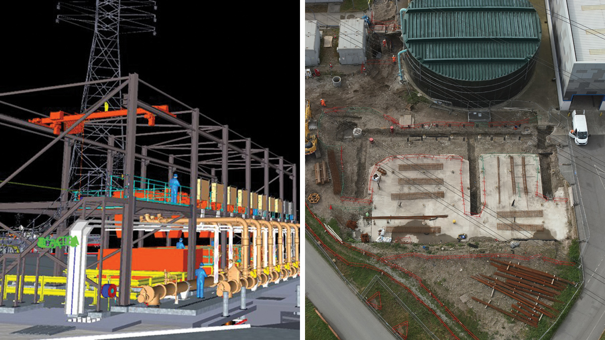
(left) Extract from 3D BIM model: raw sludge screens and (right) raw sludge screen civil works – Courtesy of Laing O’Rourke
Digital build
Laing O’Rourke’s construction assurance procedure requires the use of digital build models prior to construction. Whilst the federated model aims to show the permanent works, the digital build process aims to incorporate both permanent and temporary works requirements by reconstructing the model using 2D outputs from detail design. This has allowed Laing O’Rourke to minimise health and safety risks by planning the build with better accuracy.
Drone deploy
To monitor progress in construction, drone technology has been used to capture photos and videos. Drone Deploy platform which utilises the rich data captured also allows superimposition of detail design drawings showing outline of permanent works. This tool has been used effectively in collaboration meetings to demonstrate progress or to resolve complex engineering problems, and to plan construction activities.
Point Cloud surveys
Point Cloud surveys have been used to inform the detail design. This method of survey that capture fine details of location of civil assets and MEICA plant and equipment in 3D format. Although, it requires careful treatment before incorporating into the 3D model. In particular, areas with high density of MEICA plant and equipment such as the sludge tanks, existing grit channel at the inlet works, and existing cake barn ventilation were surveyed using Point Cloud surveys.
Design challenges due to scale – constant velocity channel and grit bridges design
The scale of the works at Beckton STW created several design challenges around plant sizing, meeting performance requirements and space constraints. One example of this being the grit removal solution on the new inlet works. Conventional design methods for calculating grit channel lengths have been challenged. CFD modelling has been used to size the constant velocity grit channels and to demonstrate the proposed location of flow measurement devices are acceptable. This has reduced the length of the channel by 23m and hence the cost of civil infrastructure.
The pumps in the grit bridges are specified to remove up to 3.5kg/s and calls for an automatic system with level instrumentation to detect grit. This would make the classifiers ones of the largest in Europe. Borger Pumps and SAVECO Environmental Ltd are providing rotary lobe type pumps to achieve the specified rate. This design rate of removal is exceptionally high, taking into consideration the incoming grit from the Tideway Tunnel.
As detection systems in this scenario are not usually required in the UK, market research had to be undertaken to select the detection system in discussion with the supply chain with their experience from other industries to reach to a solution.
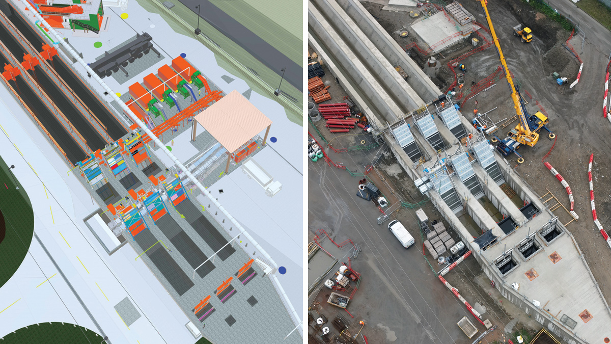
(left) 3D BIM model of new inlet works screens and (right) new inlet works forebay with coarse and medium screens upstream of the constant velocity grit channels – Courtesy of Laing O’Rourke
Beckton STW: Supply chain – key participants
- Main contractor: Laing O’Rourke
- Designer: Atkins
- UXO pile probing: Safelane Global Limited
- Piling & earthworks: Expanded Piling
- Sheet piling: Sheet Piling (UK) Ltd
- Mini piling: Keller Limited
- Tunnelling works: Joseph Gallagher Ltd
- Diving support: DiveCo Marine Limited
- Structural steelwork & cladding: Gallaway Construction
- Pipelaying: J Murphy & Sons Limited
- Structural steel: Reidsteel
- Precast walls to the FST tanks: A-Consult Ltd
- Blockwork: Pyramid Builders Limited
- Precast tank walls: Explore Manufacturing
- Access steelwork (ASP4): Steelway Fensescure Limited
- Specialist cable installation: Elsym Installations Limited
- Electrical installation inlet & ASP4: AVRS Systems
- Fibre optic installation: VVB
- Low voltage assembly (inlet): Total Automation & Power
- Transformers: Winder Power Group
- Mechanical installation: Fluid Sealing & Engineering Ltd
- Desalination pipeline diversion: Franklyn Yates Engineering
- HV switchboard & switchgear: Baldwin & Francis
- Power management: Regulateurs Europa Ltd
- HV switchboard & installation: Siemens PLC
- Inlet works & raw sludge screens: Huber Technology
- Grit bridges: SAVECO Environmental Ltd
- Grit bridges control panel design/build: Te-Tech Process Solutions
- Grit bridges instrumentation: VEGA Controls Ltd
- Rotary lobe pumps: Borger Pumps
- Grit classifiers: FLSmidth
- Blowers: Howden UK Limited
- Aeration diffusion grid: Xylem Water Solutions
- SAS gravity belt thickeners: Kent Stainless Ltd
- Glass coated steel tanks: Stortec Engineering Ltd
- Odour covers: MSD Design Limited
- Penstocks & stoplogs: Glenfield Invicta Ltd
- Scraper bridges: Jacopa Limited
- Valves: AVK UK Ltd
- Tank mixing: System Mix Limited
- Inlet washwater booster set: Crown House Technologies
- Odour control: Odour Services International Ltd
- CTM screenings belt conveyors: CTM Systems Ltd
- Diesel generator: DTGen
- GRP LVA inlet kiosk: Morgan Marine Limited
- Polymer plant: Richard Alan Engineering Company Limited
- Overhead cranes: Bramley Engineering (Lifting Gear) Ltd
- Skip compactors: Thetford International Compactors
- FE washwater break tank: Forbes Technologies Ltd
- Welfare & plant: Select Plant Hire
Construction
Collaboration
The team have strived to maintain collaboration at all levels throughout the project to support health and safety focus, sustainability and dealing with site challenges. In line with the approach in design development and approvals, collaborative planning sessions and workshops have provided great insights in problem solving and the planning of complex tasks, for example the diversion of a 132kV cable, tie in details of the new inlet works to the existing inlet works channel and materials management plan (MMP) for dealing with excavation arisings.
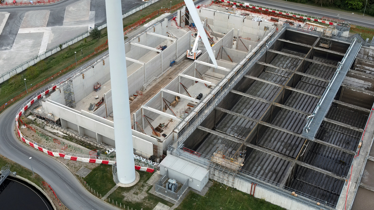
ASP4 North Tank under construction – Courtesy of Laing O’Rourke
Sustainability
The project aims to minimise off-site landfill disposal by re-using spoil for engineering works or redistributing it on site through landscaping activities and creating additional biodiverse habitats. This has been the strategy included in the MMP from the inception of the project. This has been reviewed and updated with new information rising during the construction activities.
Any contaminated sections of the excavated materials were monitored with greater scrutiny, supported by chemical testing and analyses. Localised treatment has been implemented complying with environmental standards. For instance, the identification and safe method of disposal of soil contaminated with Japanese knotweed has been carefully selected with engagement from all stakeholders and planning requirements.
The above measures have assisted in ensuring construction activities are conducted in a sustainable manner.
Another area where sustainability has been considered is in concrete mix design. Due to the large volume of concrete required on site, the use of ground granulated blast furnace slag (GGBS) has been maximised in line within the parameters defined in the project specifications. This has assisted in reducing carbon footprint of the project.
Overcoming challenges – Cadent gas main diversion
An example how a complex engineering problem was solved in close collaboration with key stakeholders is the resolution of the crossing of the Cadent gas mains to enable the construction of the new inlet works channel. The new structure had to cross an intermediate pressure steel 600mm diameter gas main and a medium pressure 30” cast iron main which then split into two polyethylene (PE) mains. The mains then cross beneath the historical Victorian NOS brick barrels.
Engagement with Cadent instigated extensive and detailed assessments of the existing gas mains, this identified the need for the MP cast iron main to be replaced due to excessive ground settlement driven by changes in ground levels. The medium pressure gas main was replaced with a new 750mm steel main, which included a section inserted into a microtunnelled concrete sleeve underneath the NOS. In addition, pipe protection measures using polystyrene blocks and lightweight fill were required to minimise the loadings on the intermediate pressure mains.
New 45m diameter FSTs under construction – Courtesy of Laing O’Rourke
Engineered safety – DfMA
DfMA has effectively been driven by Laing O’Rourke as part of their design development. The level of detail and timing of coordination required between the manufacturing team and designer was clarified early in the programme to ensure an alignment of principles, opportunities, and understanding of the likely constraints. Following are some examples of the benefits that DfMA has given.
Aeration tanks and FSTs
Precast concrete water retaining solutions are common within the water industry. At Beckton STW, the project has benefitted from incremental innovation of the previous project solution for the construction of the aeration tanks.
The twin wall solution has incorporated lessons that resulted in modifying the lateral support beam tie-in arrangement, simplifying the formwork for the pouring of concrete in between the twin wall, and minimising site effort by reducing the complexity at the concrete panel connection interface points. These provided benefit in requiring less working space, plant, and labour, thereby also improving productivity. Furthermore, regarding embedded carbon, the DfMA solution is carbon neutral compared to an in situ tank. Though the same materials are used in similar quantities there has been a 5% reduction in wastage. DfMA has also been used in the design and construction of the final settlement tanks, where post-tensioned precast walls have been utilised by A-Consult Ltd.
Engineered safety: (left) use of access hatch to internally access FST during precast wall installation and (right) use of RMD soldiers for aeration tank construction – Courtesy of Laing O’Rourke
ASP4 tank walkway handrailing
The installation of walkway handrailing from Steelway Fensecure Ltd has been developed for this project and proven to reduce the site installation period and improved safety by reducing the working at height requirements. The lifting operations have benefitted from the site already having large lift capacity craneage and the construction logistics have enabled access into the working areas to align with the civil engineering works. Systemising pipework and cable containment onto the walkways for future projects are the next generation opportunities to be investigated.
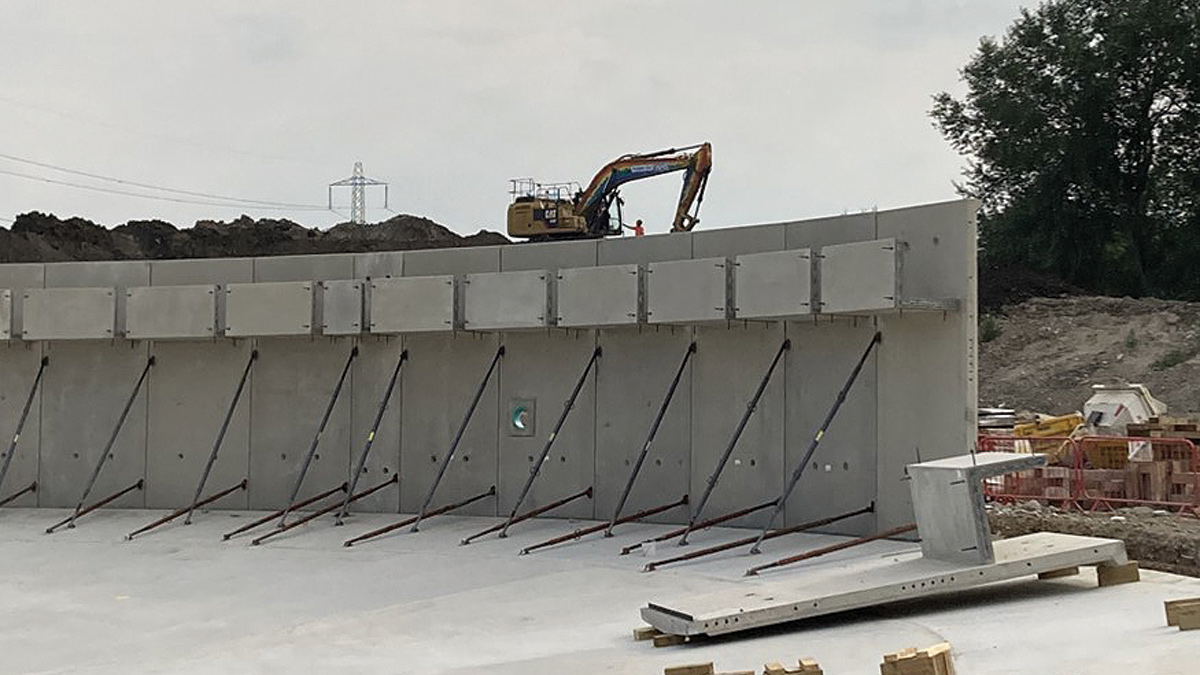
Use of RMD soldiers for twin wall propping
A simple solution to negate the use of inclined props to create more workspace and reduce hazards is to use RMD soldiers. This required careful planning from the design of twin wall during temporary phase and ensuring appropriate measures are in place within the panels to allow safe fixing of the RMD soldiers in place.
Access hatch to FST walls
Another example of a simple solution to reduce safety risk is the provision of an access hatch to enable access during the erection of the precast panels, which was developed with the precast wall supplier A-Consult Ltd. This negated the need for providing high level access through temporary staircases and reduced risk of working from height.
The above examples emphasize the benefits of DfMA accrued at Beckton STW of an improved product, reduced installation period, and the on-going development opportunity that has made construction activity safer. The project has demonstrated how incremental innovation can be achieved on a relatively new and stable construction method using twin wall construction techniques.
Precast construction of 45m diameter FST – Courtesy of Laing O’Rourke
Use of non-piled solution
As old structures have been historically filled with mass concrete to significant depth, the reuse of these mass fill structures as foundation for new structures was explored as a safer and more sustainable solution. This enabled the project team to avoid the need for mobilising piling rigs, reduce lifting requirements and need for heavy plant and equipment. High-risk service diversions of were also avoided.
The SAS thickening system comprising the GBT building, polymer facility, potable water supply facility and the SAS storage tank all are founded on the existing mass concrete foundations. The choice of foundations was supported by structural analyses and further ground investigations.
Designer tours
To instill a culture of continuous improvement, designer tours encouraged the main designer and those from trade contractors to visit the site, inspect works being undertaken and provide feedback on how hazards are being mitigated on site. The aim being to capture feedback and consider them in future design work on Beckton STW and other projects.
Commissioning and handover
Preparation for commissioning started well in advance with different sequencing of activities and scenarios discussed with Thames Water and factored in the programme. Several factory acceptance tests (CFATs) have successfully been undertaken for the diffusers in the aeration tanks, inlet works screens, grit classifiers and transformers. The sequence of commissioning activities will lead to a ‘power on’ milestone, followed by dry and wet commissioning when flows are allowed to pass through the works.
With a large pool of subcontractors and four main sections of work, Laing O’Rourke are setting up tools and systems to track and collate documentation which will in turn be required to be handed over to Thames Water and for Laing O’Rourke records.
This ranges from records of testing, operation and maintenance manuals, training documents, to design assurance documents and quality records. The philosophy adopted is to aim for a continuous handover of documents as and when they are ready, instead of waiting up to the end of the project.
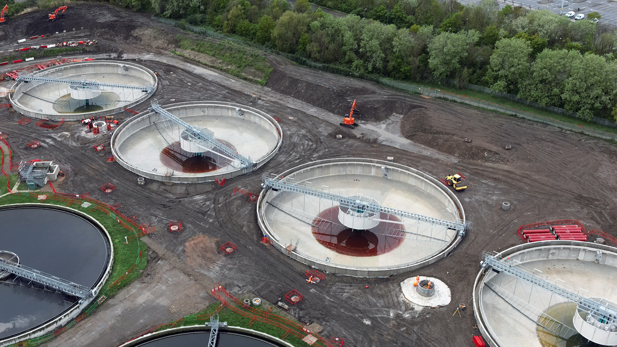
New FSTs with backfilling underway – Courtesy of Laing O’Rourke
Construction progress
The construction of the new inlet work is progressing well with most of the channel structure completed. The upstream and downstream connections to the existing channel will be the last activity before wet commissioning. The new inlet works has transitioned into the mechanical and electrical phase with the installation of the plant items underway.
Good progress has been made with the new aeration tanks that are fully constructed and water tested, with diffuser pipework and diffusers installed. The blower house and final settlement tanks have been constructed. The focus is on progressing the aeration blower installation and associated electrical works.
The civil works for the sludge area is underway in preparation for the mechanical and electrical plant installation. Overall, the project is on track to complete various works elements throughout 2024 and will be handed over in a phased approach.
