
Welsh Water Manganese & Iron Removal (2024)
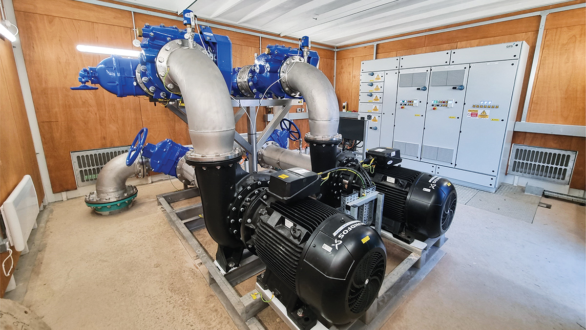
Constructed pump-skid with Grundfos pumps and bottom-entry MCC within the security-rated kiosk - Courtesy of Mott MacDonald Bentley
Dŵr Cymru Welsh Water’s (DCWW) PR19 business plan for AMP7 identified several schemes to minimise customer contacts, including water discolouration and taste/odour, against the customer Acceptability of Water measure. This is a historic challenge in Wales, driven by both raw water characteristics and the prevalence of unlined iron trunk mains. At one of Welsh Water’s water treatment works, raw water is dosed with a ferric sulphate coagulant, followed by a polyelectrolyte flocculant, before entering 28 inverted pyramid clarifiers, where the flocculated particles are retained in a sludge blanket. The clarified water passes to 28 rapid gravity filters before chlorination and flows to the three contact tanks on site before entering the distribution network.
Background
Incoming flows to the works vary seasonally due to changes in the raw water supply reservoir during late summer, such as thermal stratification, which results in spikes in manganese. The increased manganese load coincides with higher iron levels in the final water as the ferric sulphate coagulant dose is increased to maintain water quality. DCWW employed Mott MacDonald Bentley (MMB) to design and build a solution to reduce manganese and iron levels.
Improving coagulant mixing was identified as the solution to reduce particulate manganese and iron levels in the final water. Coagulant mixing enables more efficient dosing of ferric sulphate, reducing iron levels, and supports floc formation that better captures raw-water contaminants such as manganese while reducing turbidity. At the clarification stage, the inverted pyramid clarifiers would see a more robust sludge blanket formation through which incoming water has to pass, ensuring particles combine into heavier flocs.
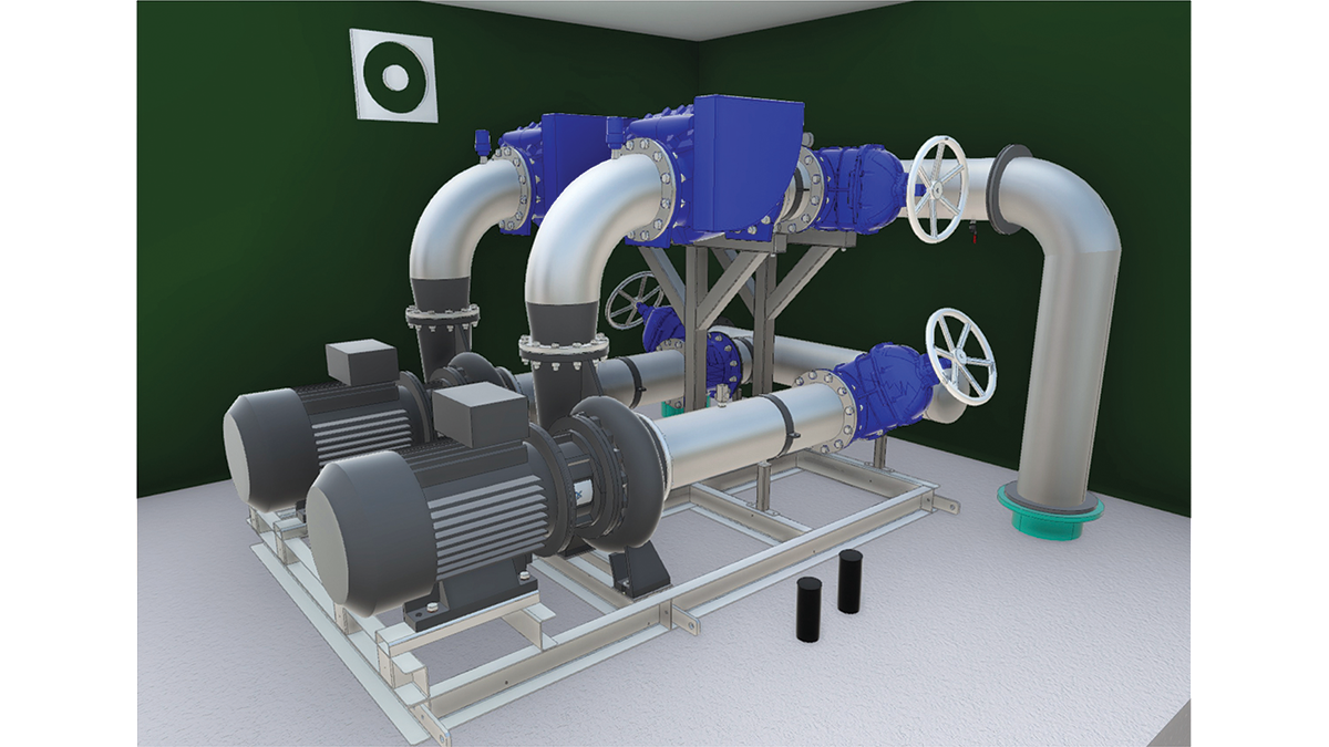
3D model of the pump-skid within the kiosk – Courtesy of Mott MacDonald Bentley
Constraints on coagulant mixing
At the existing works, ferric sulphate was dosed into the incoming main through pairs of injection lances, and there was previously no method of mixing coagulant due to technological and constructability constraints. For the upgrade project, traditional mixing methods were considered at optioneering, including static mixing and mechanical mixing. Mechanical mixing was discounted because the required retention volume would have required a chamber too large to install on site.
Static mixing was discounted due to the critical 48” incoming main requiring equivalent-sized under-pressure connections and flow-stops that posed a severe risk to water supply during construction. Static mixing also increases head loss, which in this case would have reduced the WTW’s maximum capacity by affecting the fixed-speed pumps that feed the works.
With limited options for a meaningful mixing method, it was decided to design and build a jet mixing solution; a first UK application to coagulant mixing in clean water treatment.
Jet mixer basis of design
Jet mixing technology is not particularly novel and has been commonly applied to wastewater treatment for solids suspension, sludge storage, and storm tank mixing. Coagulant jet mixing has also been applied at wastewater treatment works, typically dosed into an open channel at the inlet works, where a jet of water provides mixing agitation to disperse the coagulant more effectively. In these instances, static channel mixing could have posed maintenance issues such as ragging or changes in treatment system hydraulics.
Existing mixing challenges at the treatment works
At the WTW, it was deduced that the coagulant mixing rate was too slow to ensure a uniform coagulant concentration, as mixing relied on natural turbulence within the pipe.
This issue was compounded at lower flow rates, where ambient turbulence within the pipe was lower and could not provide the necessary mixing energy. In addition, the incoming flows split into two branches before entering the clarifiers, and uneven coagulant concentration within the pipe cross-section may have resulted in more coagulant entering one branch than the other. The objective was then set that a Coefficient of Variation (CoV) < 0.05 must be reached within the pipe before the flow was split.
Proposed jet mixing solution
Framatome Ltd was employed to carry out the technical investigation and analysis into the current and proposed mixing performance to form the basis of design for the jet mixing solution. The initial investigation confirmed there was poor mixing at all works flow rates. Framatome Ltd then completed an outline jet mixer design with CFD verification to meet the mixing objectives with an approximately 10-fold improvement on time to reach a CoV < 0.05 and, most importantly, before the flow split to the clarifiers.
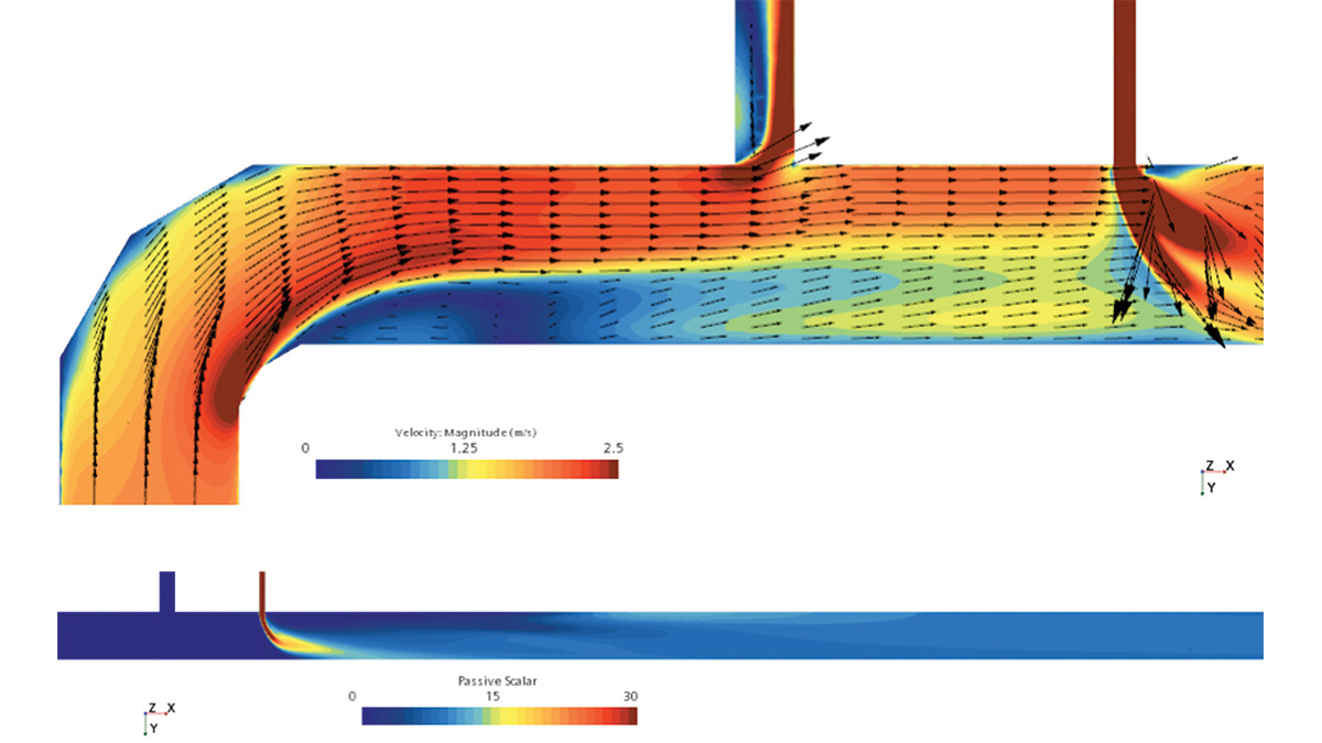
CFD verification of the jet mixer – Courtesy of Framatome Ltd
The outline solution
Details of the proposed jet mixing solution are as follows:
- A suction line tee-off from the 48” inlet main receives a small portion of the works flow that is fed to duty/standby end-suction centrifugal pumps with a variable speed drive (VSD). The pumps are VSD driven to minimise energy consumption and reduce OPEX by adjusting the pump speed according to the treatment works flow.
- The pump discharge then returns the raw water through a small diameter static mixer which becomes the new point of application for coagulant dosing.
- After ‘pre-mixing’ the solution, the discharge pipe diameter is decreased to increase the jet flow velocity before entering back into the inlet main just downstream of the suction point.
- The high jet flow velocity ensures there is sufficient mixing energy to effectively mix the coagulant in the main within 10 to 12 seconds.
Scope of works
The main elements of work included:
- Installation of two welded underpressure tees to an existing 48” steel main.
- Precast concrete chamber and cover slab with security-rated access covers.
- DN350 static mixer.
- Duty/standby pump skid with VSD centrifugal pumps.
- Installation of approximately 210m of epoxy-coated steel and HPPE pipework between the underpressure tees and the pumps.
- Installation of a bottom-entry Form 4 MCC.
- Installation of a security-rated kiosk.
- Concrete road extension to the new kiosk.
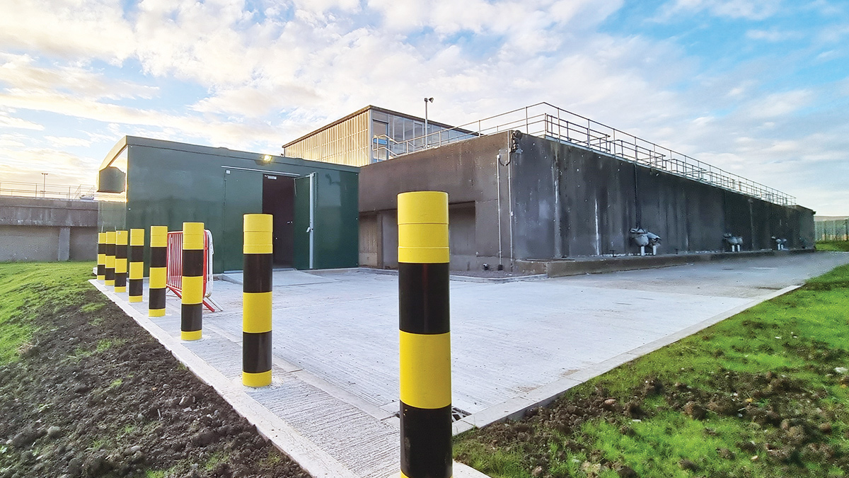
External view of the kiosk and road extension – Courtesy of Mott MacDonald Bentley
Supply chain – key participants
- Client: Dŵr Cymru Welsh Water
- Principal contractor & designer: Mott MacDonald Bentley
- Technical investigations: Framatome Ltd
- Geotechnical: Mott MacDonald
- Ground investigations: Spencer Quantum
- Groundworks: Envolve Infrastructure
- Hydro-demolition: Sabre Jetting
- Underpressure tees: UTS Engineering Ltd
- Electrical installation: Celtic Process Control Ltd
- Mechanical installation: Tema Group
- Systems integration: Oasis Software Solutions
- MCC: GPS Group
- Steel pipework: George Green (Keighley) Ltd
- Steel pipework: Freeflow Pipesystems
- HPPE pipework: Radius Systems
- Kiosk: Morgan Marine
- Static mixer: Statiflo International
- Valves: AVK UK Ltd
- Pumps: Grundfos Pumps Ltd
- Pump skid: KGN Pillinger
- Precast concrete: FP McCann
- Access covers: Technocover Ltd
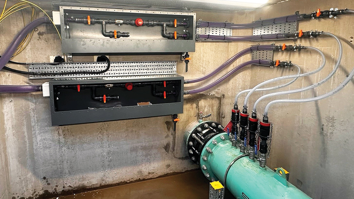
Ferric sulphate point of application in the underground precast concrete chamber – Courtesy of Mott MacDonald Bentley
Construction and challenges
After receiving the outline design from Framatome Ltd, MMB carried out the detailed design of a constructable and commissionable jet mixing solution.
The design involved a precast reinforced concrete chamber with a cover slab that serves as the ‘mixer chamber’ in which the static mixer and the coagulant point of application is located. The suction and discharge points were installed as two steel under-pressure tees that were welded onto the 48” steel main after being exposed from its concrete surround with hydro-demolition.
Site cabin power supply: It was recognised early on that the site cabins would require a large amount of fuel to power them, and would produce significant noise pollution. It was therefore agreed that the site cabins would be connected to the WTW power supply to significantly reduce fuel costs and mitigate environmental hazards during the construction programme.
Hydro-demolition: The construction area was situated adjacent to a training academy on site at the WTW, so measures were taken to protect the building and reduce noise levels during hydro-demolition. Scaffolding with acoustic barriers was installed to encapsulate the working area.
Underpressure connections: Welded tees were installed instead of mechanical tee fittings to provide a more permanent fixture to the main and reduce the risk of leakage. An added benefit of using welded tees was a reduced programme and safety risk during hydro-demolition.
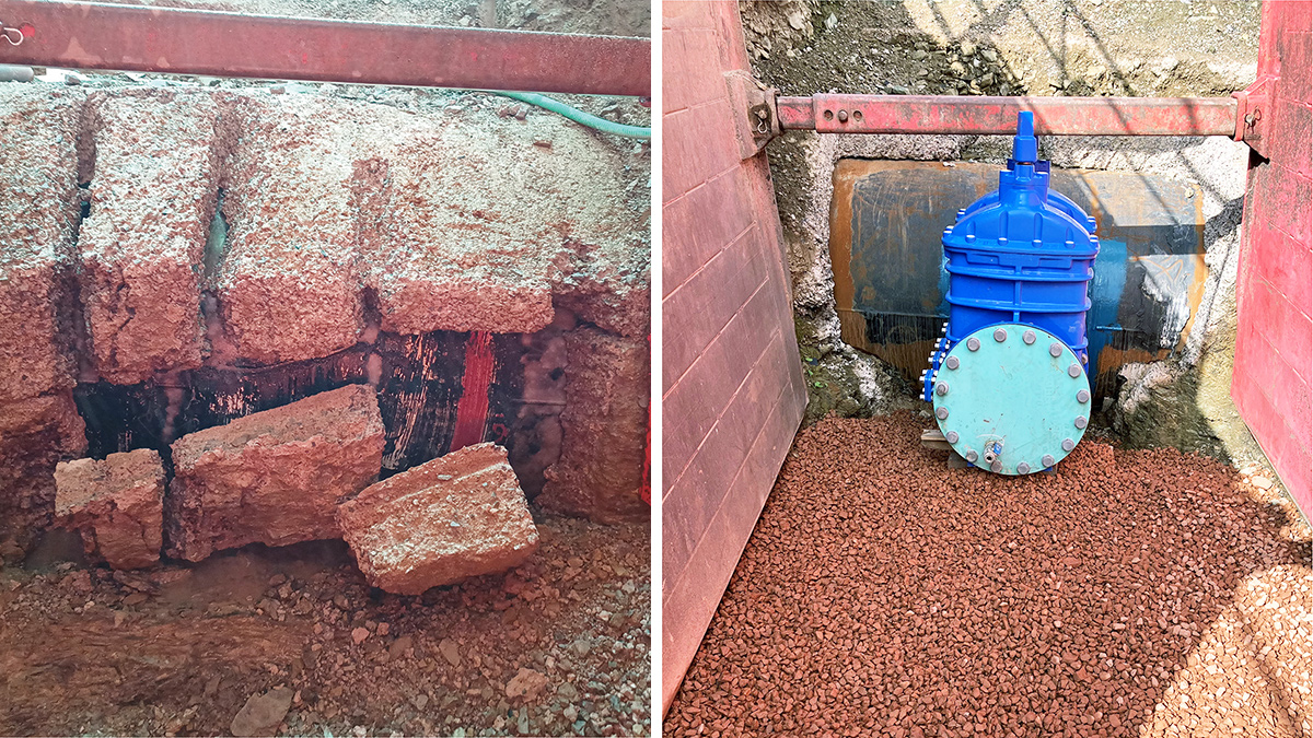
(left) Hydro-demolition carried out on the concrete surround of the existing 48” main and (right) DN400 underpressure connection with a welded tee on the existing main – Courtesy of Mott MacDonald Bentley
Site topography: The site’s challenging topography required custom steel pipes with complex geometry for some parts of the suction and discharge legs. The bulk of the remaining suction and discharge legs were constructed with SDR17 HPPE, which better followed the site topography, joined with electrofusion couplers. HPPE pupped stub flanges were installed where material transitions occurred between PN16 steel pipework and SDR17 (equivalent to PN10) HPPE pipework. An electromagnetic flow meter was also installed to verify the pumped jet flows.
MCC and DfMA pump-skid within a kiosk: The duty/standby pump skid was manufactured and delivered as a DfMA product and installed within a 5.5m x 6.5m x 3.0m security-rated kiosk. The pump suction and discharge manifold pipework was manufactured using 316L stainless steel and supported by a galvanised mild steel skid structure.
A bottom-entry Form 4 MCC was also installed within the kiosk and situated atop a precast concrete service trench, providing ample room for access and maintenance below the MCC.
Testing & commissioning
Coagulation is a critical part of the water treatment process, so a comprehensive risk assessment was essential to ensure the works could continue to produce drinking water during commissioning.
Recognising this importance, and by applying an innovative mixing method, a robust design and commissioning methodology was devised to mitigate the risk of loss of supply. The existing point-of-application arrangement remained in place as a standby, and the existing pipework was modified to allow a valve arrangement and connection to the new point of application.
If any issues were encountered with the new mixing arrangement during commissioning or operation, ferric dosing can be quickly reverted to its original regime.
However, through rigorous planning, the jet mixer was successfully commissioned, and no mitigation measures were required. Following commissioning of the jet mixing system, water quality trends on the SCADA system showed an almost instant improvement in treatment performance at the works, and work is ongoing to further optimise treatment performance.
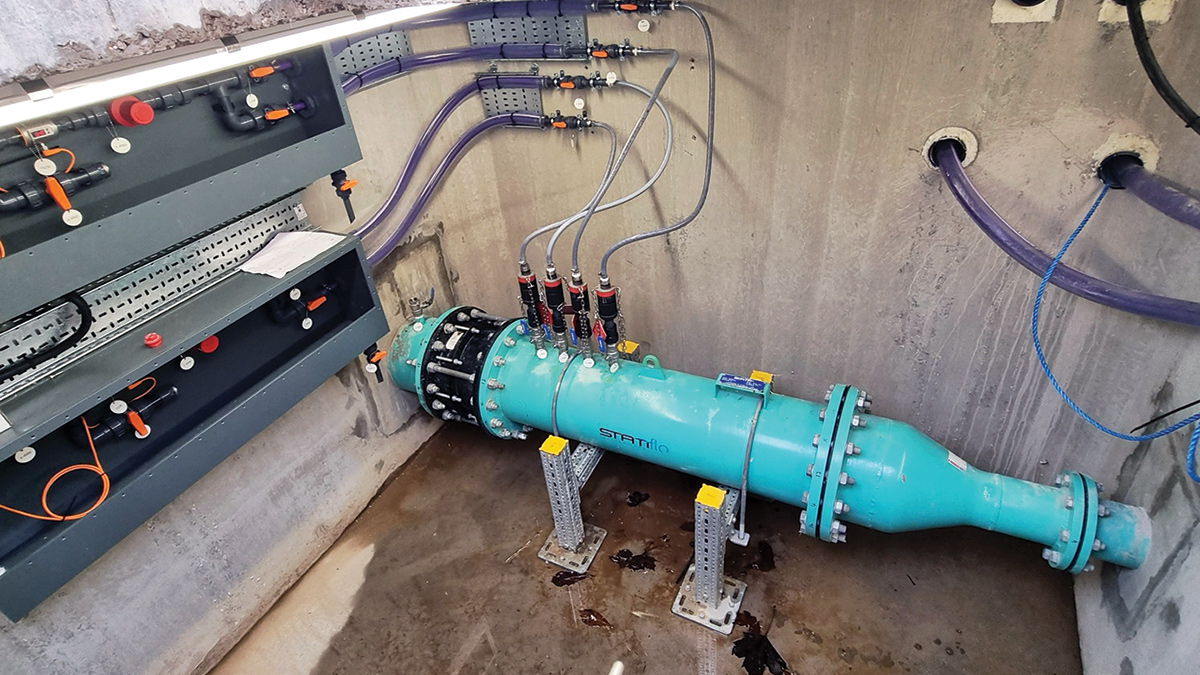
Static mixer and reduction in pipe diameter to increase the velocity of the jet flow before injection into the existing main – Courtesy of Mott MacDonald Bentley
Process benefits
- Clarifier turbidity levels improved.
- 46% mean reduction of clarified water turbidity.
- Clarifier iron levels improved.
- 48% mean reduction in clarified water iron levels.
- Filter headloss reduction.
- 20% to 40% reduction in filter headloss, allowing for filter run times to be extended and reducing washwater production.
- Reduced chlorine demand.
- Reduced post-clarifier hypochlorite dosing, indicating the Cl2 setpoint is being achieved more effectively with less chemical dosing. This suggests there is better organics capture through the clarification stage.
- Post-RGF filter disinfection turbidity decreased by over 50%.
- Ferric sulphate coagulant dosing rate reduced by 35%.
Conclusion
Through excellent collaboration between Welsh Water and Mott MacDonald Bentley, this innovative solution to coagulant mixing was completed in November 2023, ahead of programme.
Jet mixing has been successfully implemented and demonstrated to deliver water treatment process benefits and provides an alternative to mixing solutions where site constraints make traditional mixing options infeasible.
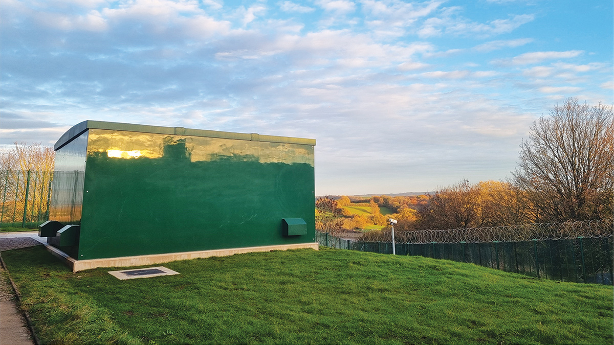
External view of the kiosk - Courtesy of Mott MacDonald Bentley