East Worthing WwTW (2020)
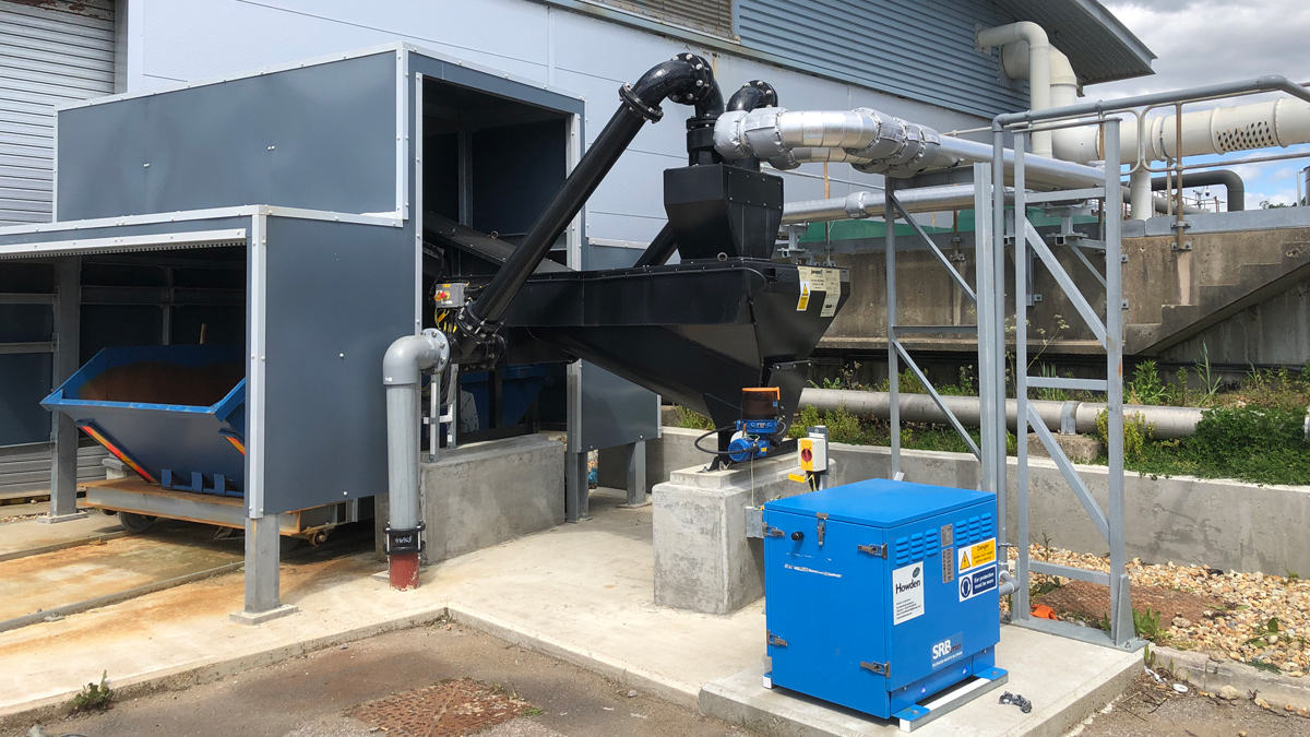
New grit transfer and collection bay - Courtesy of BTU
Located close to the English Channel, East Worthing WwTW serves a population of 140,000 in a largely urbanised area in West Sussex. In peak wet weather conditions, up to 71 million litres can flow through the site in a day. Due to the urban nature of the catchment, and some large and relatively shallow gradient sewers, the treatment works suffers from grit build-up. The existing grit removal system had been out of action for some years, causing excessive wear on the downstream assets and the lack of full primary treatment resulted in odour complaints from nearby residents. In 2019 BTU Utilities were appointed to replace the entire grit removal system.
Background
Wastewater enters the treatment works via a 2.4km sewer that terminates in a deep shaft pumping station. The wastewater passes through two vertical inlet screens into the inlet pumping station wet well. Dry weather flow received in the inlet wet well is pumped to the head of the treatment works and subsequently gravitates into the grit removal system. Flows that exceed the permitted rate are pumped to the long sea outfall, or if the flows are particularly severe, they are pumped to the short sea outfall.
Flooding had occurred in the underground grit pump room, causing all pumps to fail and preventing the adequate removal of grit from the existing detritors. In turn this caused an overload of grit, damaging the scrapers and requiring a complete overhaul of the system.
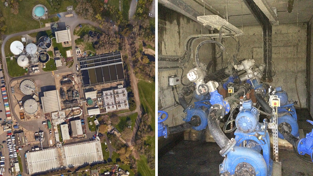
(left) Google Maps image of East Worthing WwTW and (right) flood damage of original installation – Courtesy of BTU
Project scope
The project required the complete upgrade and replacement of the original grit removal process, comprising:
- 2 (No.) 8m diameter Jones + Attwood Crossflow detritor.
- 3 (No.) Jones + Attwood grit pumps.
- 1 (No.) Jones + Attwood grit classifier c/w skip trolley and waterproof shelter.
- 1 (No.) intelligent MCC with SCADA integration.
- System-wide process instrumentation and system integration.
- Full mechanical and electrical installation.
The detritors
The new Crossflow detritors can handle a maximum flow rate of 2200 l/s (1100 l/s each). To ensure there is some resilience and redundancy in the assets, the upstream storm weir point has been designed to limit the flow to the Crossflow detritors at 1990 l/. Operation is in a duty/duty/assist/standby determined by the level in the corresponding inlet channel.
Due to the site constraints when East Worthing WwTW was originally constructed, pumped flow from the inlet works pumping station gravitates from the reception chamber, through a very tight horseshoe-shaped channel. The horseshoe inlet channel then splits into two parallel inlet channels, serving each Crossflow detritor section. A series of bespoke vertical baffles were designed and installed to assist with the retardation and distribution of flow entering the collection tanks.
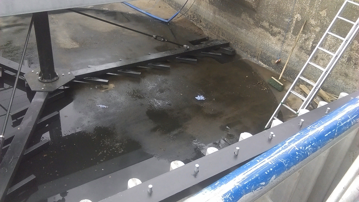
New detritor installation – Courtesy of BTU
The design of the chamber enhances flow equalisation across the Crossflow detritor chamber and it also ensures flow across each is in a single direction across the tank to the outlet side; maximising the settlement performance of the grit and fine aggregates. This design forms a recessed, circular sump. The 8m diameter is equivalent to the length of the square sides of the tank, maximising the area-to-volume ratio. The ground level of this sump is the bed upon which the grit and other similar solids settle. This accumulation of solids is collected and transported by a slowly rotating scraper mechanism supported on the bridge spanning the tank.
The collected solids are delivered to a hopper located on the periphery of the tank where they are collected prior to being transferred to the classifier by three grit pumps. The grit pumps are located within a dry well pumping station situated between the two Crossflow detritors. From here the grit is pumped by specialised hard-wearing grit pumps. The pumps are a recessed, vortex flow-type impeller with a full 100mm diameter solids freeway, with a duty flow rate of duty of 13 l/s at a 4m head. The pumps operate on a duty/duty/standby and each Crossflow detritor affords a dedicated duty pump. Additionally, there is a common standby pump linked to each Crossflow detritor hopper, to maintain the process should either fail. In the event of a failure, actuated valves operate to enable the standby pump to transfer flows from the hopper to the classifier via either of the delivery main. The pumped flow rate from each pump is monitored by dedicated flow meters, should the delivery flow from each pump fall below a pre-set point, when standby pump will automatically assume duty.
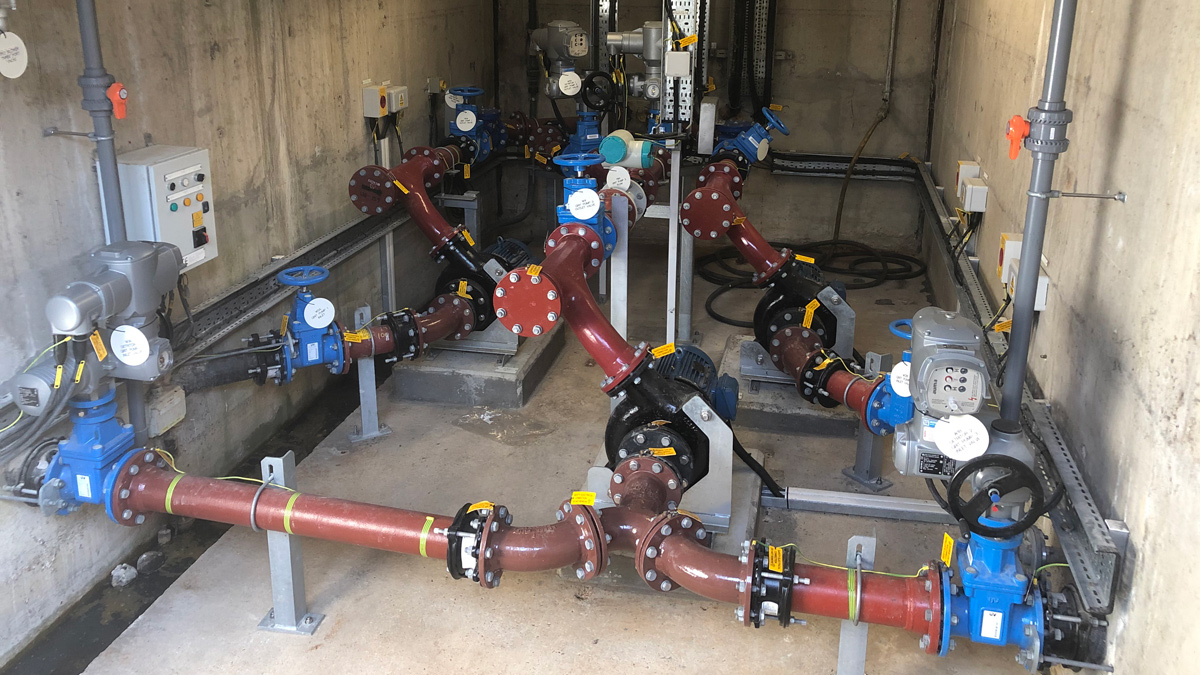
New pumps, pipework and valve installation – Courtesy of BTU
Undertakings
The programme was delivered under BTU Utilities’ React & Maintain (R&M) Framework with Southern Water. The framework covers planned and reactive maintenance as well as capital project delivery for infrastructure and non-infrastructure projects across the entire Southern Water region for AMP7; expiring in 2025. The contract also consists of a unique innovation partnership with Southern Water to ensure all opportunities for innovation and R&D are fed into projects.
East Worthing WwTW grit removal project: Supply chain – key participants
- CDM & project management: BTU Utilities
- Civil design: Trant Engineering
- Electrical & process design: BTU Utilities
- Mechanical design: Jacopa
- MCC: MCS Control Systems
- Jones & Attwood Crossflow detritor: Jacopa
- Jones & Attwood grit pumps: Jacopa
- Jones & Attwood classifier: Jacopa
- Blowers: Howden Blowers
- Flow controls: Auma Actuators
- Electrical installation: BTU Utilities
- Mechanical installation: Jacopa
- Odour control covers: Corporate Engineering
- Skip trolley & shelter: R&B Engineering
- Electrical material: R&M Electrical
- Instrumentation: Siemens
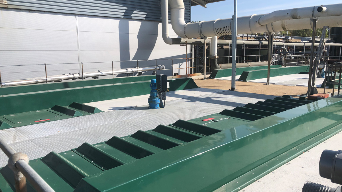
The existing odour control covers had delaminated making them unsafe to walk on – Courtesy of BTU
Conclusion
The project was successfully completed on time despite some of the difficulties with the small foot print. The new detritor units are outperforming expectations, with skips getting full in twice the time as before.


