Fleetwood WwTW Stormwater Storage (2015)
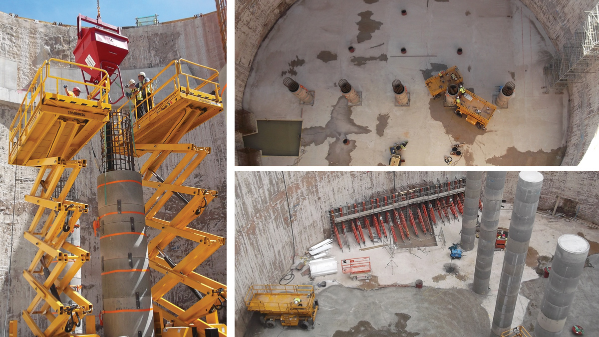
(left) Using PCC manhole rings as permanent formwork, (top right) base slab showing the rebate and columns and (bottom right) formwork for shaft eye - Courtesy of Donaldson Associates
In order to help reduce the spill frequency of untreated stormwater on the Fylde Coast in Lancashire, a new storage tank was required to provide an additional storage capacity of 15,000m3. The new tank was to be located at the existing Fleetwood WwTW and was completed within AMP5, delivered on programme and within budget. This article highlights the successful collaboration between a number of designers, main contractors and sub-contractors throughout the build.
Background
Prior to this project, the WwTW consisted of two tanks (Tank 1 and Tank 2) which held wastewater before treatment. However, due to the spill frequency on the Fylde coast, of which Blackpool beach is one of the main tourist attractions, additional storage of 15,000m3 was required. This was to be achieved by constructing a new tank (Tank 3) and connecting it to the existing network via a tunnel. A new penstock was also to be installed and this resulted in the requirement to construct an additional tank (Tank 4). Tank 4 doubled as the tunnel drive shaft. Tank 3, Tank 4 and the tunnel all contribute to the storage volume of 15,000m3.
Project requirements
The project consisted of the excavation and construction of a 40.55m internal diameter (ID) tank (Tank 3) and an 8.55 m ID tank (Tank 4). Both tanks were constructed as shafts to depths of approximately 25m below ground level (mbgl) using diaphragm wall construction. These tanks were connected by constructing a 40m long, 1.8m ID tunnel 20mbgl by pipe-jacking techniques. The system was then connected to the existing storage network, which consisted of Tanks 1 and 2 constructed in the 1990s, by hand mining a short connection from Tank 4 to Tank 1.
Prior to the commencement of tunnelling, the ground required treatment by jet grouting in order to stabilise it and mitigate water ingress prior to launch of the tunnel boring machine (TBM).
The tank internals comprised a number of complex and challenging reinforced concrete (RC) details including a base slab (4.75m thick and 6,000m3), 5 (No.) RC columns (1.2m diameter, 18m high) and an RC Corbel ring beam to support a buried roof structure. The roof structure comprised 16 (No.) precast prestressed concrete (PCC) bridge beams, permanent formwork and an RC slab (250mm thick) which was covered with 4m of selected backfill to provide deadweight and act against shaft uplift. RC headwalls associated with the tunnelling works were also built.
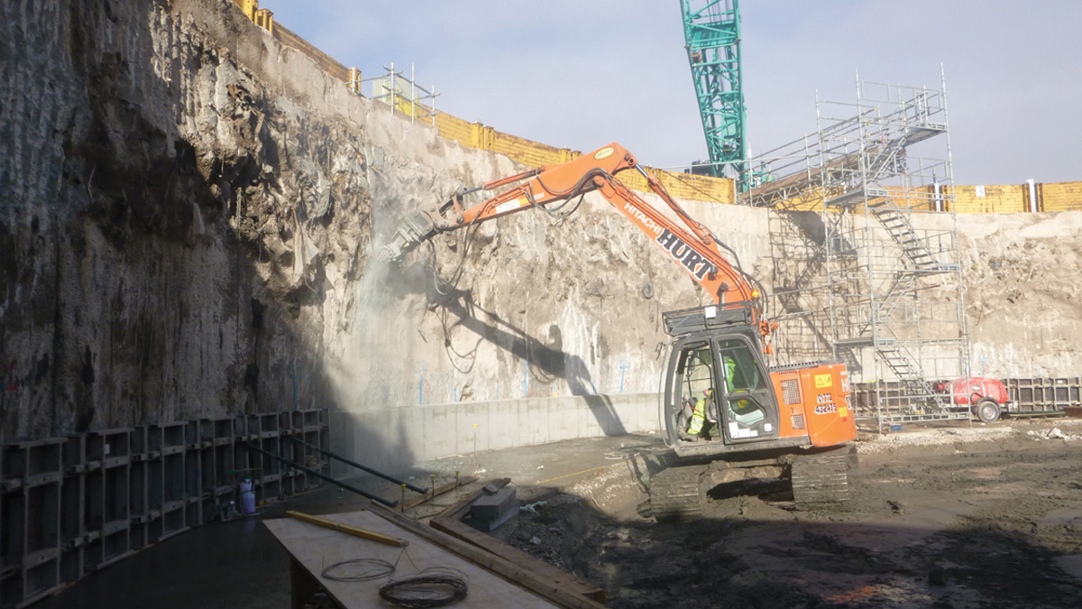
Removing D-wall overbreak – Courtesy of Donaldson Associates
Undertakings
The designers worked closely and the design developed at a fast pace.
- Main Contractor: KMI+ (Kier Murphy Interserve JV)
- Designer: Donaldson Associates Ltd
- Diaphragm Wall Contractor: Bachy Soletanche Ltd
- Jet Grouting Contractor: Bachy Soletanche Ltd Specialist Geotechnics Division
- Tunnelling Contractor: AE Yates Trenchless Solutions Ltd
- Specialist Precast Concrete Suppliers: FP McCann
- Specialist Precast Concrete Suppliers: Shay Murtagh Precast
The relationship between the client/concept designers, main contractor and designer was extremely good which resulted in drawings being produced both on time and to the contractor’s satisfaction. The relationship promoted discussion and there was an open door policy which helped the designers to produce an efficient and buildable design. For example, before design of complex reinforced concrete structures the designer had discussions with the steel fixers about how they wanted to build it and what was manageable on site, leading to the production of site friendly construction details.
This project also saw the use of a number of proprietary reinforcement products, including the first use in the UK of RFA-Tech Sheargrid shear reinforcement in the large base slab, anchor blocks in the corbel and the novel use of PCC manhole rings as permanent formwork for the RC columns, which reduced temporary works and propping hazards.
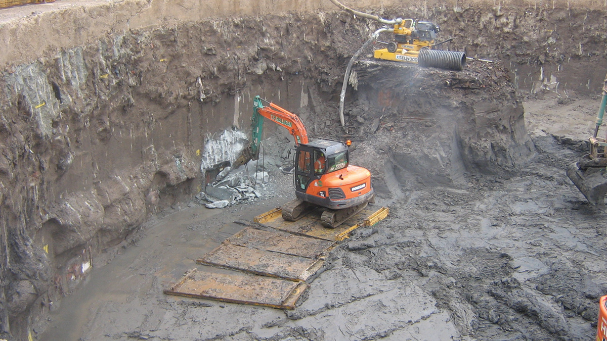
Removing D-wall overbreak – Courtesy of Donaldson Associates
Geology
The geology of the site comprised the following:
- Made Ground: 0 – 5 mbgl
- Organic Clay: 5 – 8 mbgl
- Alluvial Silt & Sand: 8 – 14 mbgl
- Glacial Clay: 14 – 16 mbgl
- Glacial Sand & Silt: 16 – 20 mbgl
- Glacial Clay: 20 – 40 mbgl
- Mudstone: 40 – ? mbgl
The top 4 to 5m of the site was previously used as a waste amenity site and it was known from the SI that the ground, over Tank 3, was contaminated with asbestos and methane gas. Also, it was noted that during a previous tunnelling job on this site in the 1990s ground freezing was required to mitigate water ingress during TBM breakthrough.
Following the site investigation, saline and tidal groundwater was encountered approximately 3m below ground level (+7.8m AOD). Due to the proximity to the coastline, there was the risk of recharge should water be encountered during tunnelling works. The early stage optioneering allowed UU, DAL, KMI+ and BSL to foster a good working relationship whilst gaining confidence in the proposed design.
Detailed Design
The design consisted of 2 (No.) diaphragm wall shafts, reinforced concrete base slabs, a shaft eye, and reinforced concrete columns to support a buried roof structure comprising precast concrete roof beams an RC slab and backfill.
To provide 15,000m3 storage, the shaft diameter needed to be 40.55m internal diameter. The diaphragm wall shafts were designed and built by Bachy Soletanche and Donaldson’s undertook a Category III check of the shafts.
The shaft was constructed by forming a trench from ground level which was supported by bentonite before the installation of concrete and the reinforcement cage. The 20 (No.) panels were 1.2m thick, approximately 6.4m wide and constructed in three ‘bites’. Each panel consisted of 3 (No.) reinforcement cages which were built at ground level before being lifted and lowered into the trench.
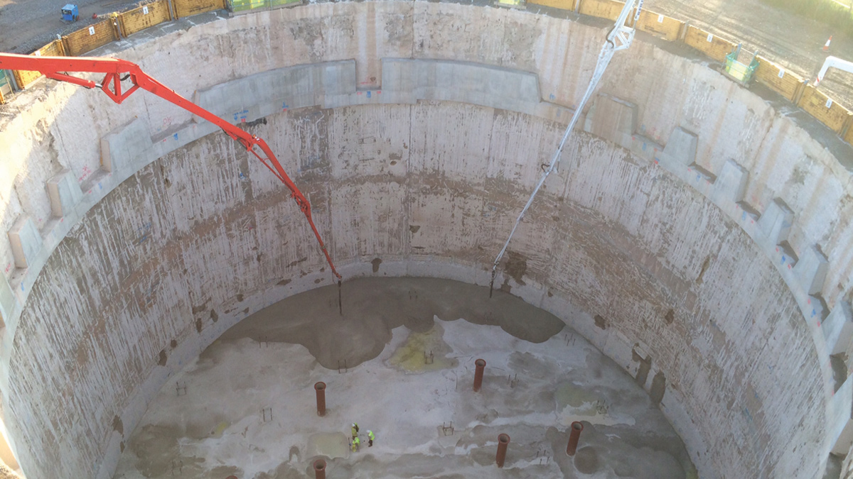
Pouring the mass concrete plug in tank – Courtesy of Donaldson Associates
The diaphragm wall provided a water cut-off at the base of the tank. This was achieved by terminating the toe of the wall in the glacial clay at approximately -23.518m AOD. This was confirmed by a geotechnical engineer from DAL based on site, to provide supervision and assurance of the final toe level. This assisted DAL in validating the ground model used as the basis for design.
Shaft internals
Following construction of the diaphragm wall shafts, the contractor excavated Tank 4 and constructed a reinforced concrete base slab. Tank 3 was excavated in two stages, stopping to construct a corbel below roof level (+0.585m AOD).
The corbel, required to support the roof structure, was 1.2m high, 450mm wide and connected to the diaphragm wall using couplers. These couplers were connected to the reinforcement cages in the wall prior to being lowered into place. The reinforcement in the corbel comprised a number of threaded bars which were screwed into the couplers in the D-wall.
In order to reduce the width of the corbel and minimise the quantity of reinforcement, a proprietary anchor block, ‘Terminator’ by Lenton Erico, was used. The construction of the corbel was quick and the steel fixers were quickly followed by a gang who installed the shutter and poured the corbel in sections. Once the corbel was constructed, a number of box-out sections were formed above it to accommodate the roof beams.
A drainage layer and 8 (No.) pressure relief pipes were located around the base to relive the water pressure in the temporary case. These pipes were cast in during the pouring of a 2m thick un-reinforced concrete plug and a 2.5m thick reinforced concrete slab (6,000m3 concrete and 300 T Steel).
The plug was not structurally connected to the D-wall, however, for flotation purposes it was connected to the overlying RC slab by means of steel ‘towers’ which acted in tension to hold the slabs together.
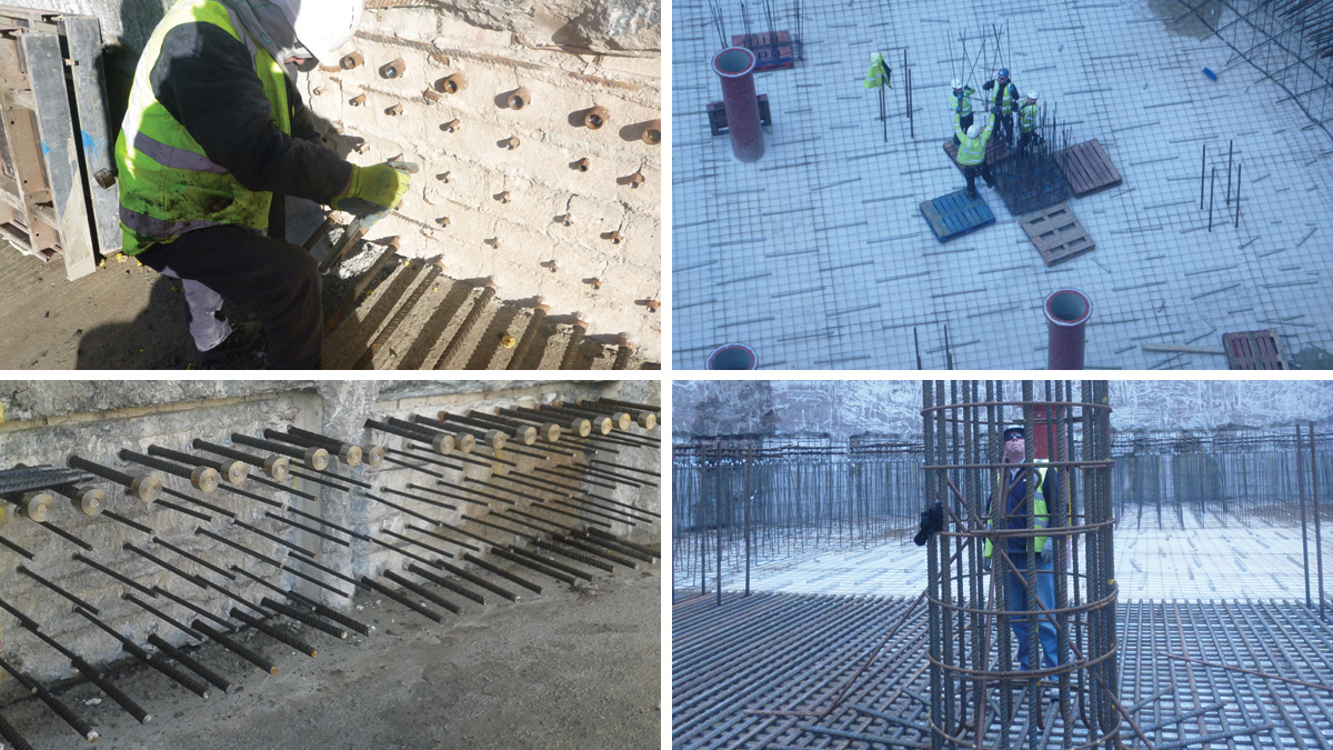
(Top left) Installation of threaded bars, (top right) fixing of the Sheargrid on site, (bottom left) corbel reinforcement and “Terminators” and (bottom right) RC column starter cage – Courtesy of Donaldson Associates
The base slab was connected to the diaphragm wall, to form a shear connection, using the same method adopted at corbel level. The base slab was reinforced orthogonally with the primary reinforcement located in the top mat, the tension face. A strip in the bottom mat, under the columns, was heavily reinforced to counteract punching. Shear links were required around the perimeter of the slab.
Following discussions regarding the concrete pour, DAL was asked to review the design and detailing of the bars to determine if it would be acceptable to reduce the concrete pour volume. The main stumbling block was the requirement for shear links in the slab and standard links would not work with the modified pour.
Therefore, DAL arranged with RFA-Tech to use the proprietary product Sheargrid. This was the first time this product was used in the UK. The bespoke grid comprised of a frame with vertical pins welded to the base. The pins were equipped with a coupler on the end which enabled the pouring of the slab before installation of the remaining length of pin. This proprietary product allowed the steel fixers much more freedom when fixing the links on site and also increased the efficiency of the work. The grids were delivered to site in a manageable size which were easy to handle and manoeuvre.
Reinforced concrete columns, using manhole rings as permanent formwork, were constructed from base level to support a roof structure composed of precast concrete bridge beams and a cast in situ RC slab. The slab was 4m below original ground level and backfilled over with clay. The clay was compacted to achieve a specified density to be utilised to resist flotation.
A large reinforced concrete shaft eye was built within the tank to transfer the hoop stress around the diaphragm wall once the tunnel had been driven. The eye was built in two stages and cast into the base slab.
Roof structure and backfill
The roof structure comprised 16 (No.) precast prestressed concrete ‘W’ bridge beams supported on the RC corbel and columns. These beams were installed very quickly using a 1,000T crane. The beams were overlain with a 250mm thick cast in situ RC slab. The beams were placed with extreme accuracy so to allow them to be connected to the corbel with reinforcement to form a continuous ring. One beam was damaged in a lorry fire on the M6 during delivery to site; the supplier, Shay Murtagh Precast, KMI+ and DAL worked quickly to ensure a replacement beam was delivered to site.
Following the pouring of the roof slab, a number of precast concrete culvert units were used to form access chimneys to ground level. The backfill used was selected from clay excavated from the tank.
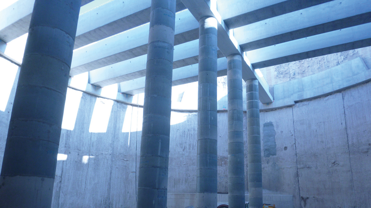
Roof structure – Courtesy of Donaldson Associates
![]() Tunnelling works
Tunnelling works
The tunnelling sub-contractor was AE Yates Trenchless Solutions Ltd (AEY TSL). A full face slurry microtunnelling machine (TBM) was used to install 16 (No.) 2.5m long precast concrete steel banded pipes between the existing and the new tanks, drive length 40m. The tunnel was driven uphill from Tank 4 to Tank 3.
During site investigation it was identified that the ground conditions would change from clay to sand midway through the tunnel drive. This presented the risk of water ingress, loss of ground and the risk of the machine diverting off course at the interface. To mitigate this, the ground was treated by jet grouting along the full length of the tunnel drive. The jet grouting was required to form strengthened low permeability break-out/break-in blocks for the TBM at shaft interfaces; between the shafts the requirement was to reduce the impact of split face tunnelling. On completion of the works 98 (No.) jet grout columns, ranging between 1.4m and 2.0m in diameter and 3 to 5m long, were installed at depths of 20 to 25mbgl.
The job followed the guide of the Joint Code of Practice for Risk Management of Tunnel Works in the UK, referred to as the JCoP. As part of the JCoP a project risk register was developed. There were a number of key stakeholders who input to the register (UU, KMI+, AEY TSL and DAL). The register allocated risks to individual stakeholders to mitigate. Regular risk review meetings were held on site and these proved to be very beneficial to the project.
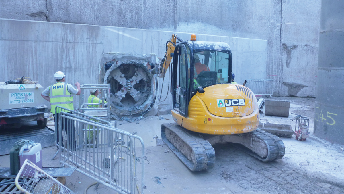
TBM breakthrough – Courtesy of Donaldson Associates
![]() Monitoring regime
Monitoring regime
Prior to the works, a monitoring regime was set up to understand the behaviour and response of the soil and surrounding infrastructure. The monitoring consisted of surveying and a number of inclinometers near to adjacent structures. Following the construction of the new shafts monitoring points were installed on these also. The monitoring regime comprised a three level trigger system (green-amber-red). The monitoring information was analysed in real time by engineers in the DAL office. It should be noted that the tunnel drive pit was approximately 5m away from a third party telecom mast.
Tunnelling operation: Tank 4 to Tank 3
Following breakout, AEY TSL had to remove some of the D-Wall reinforcement from the line of the tunnel. The tunnel boring machine (TBM) was set-up in the pit bottom of Tank 4 with the jacking rig and slurry lines. A launch seal was bolted to the diaphragm wall through which the TBM was driven, uphill, towards Tank 3.
Once the head of the machine and the back-up cans had been installed the first pipe was lowered into the tank. The first pipe was jacked into position and the rams were withdrawn prior to installing pipe 2, the process was repeated until the diaphragm wall shaft was reached at Tank 3. The TBM was brought slowly up to the back of the concrete wall and pushed through the concrete eye. The tunnelling sub-contractor managed this breakthrough carefully and successfully.
Following this, the tunnel was back-grouted using an ordinary Portland Cement grout.
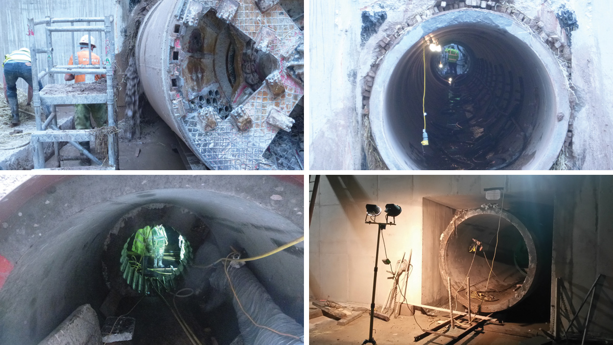
(Top left) Managing water ingress during TBM removal, (top right) installed precast concrete pipe (looking from Tank 3 to Tank 4), (bottom left) hand mined section Tank 4 to Tank 1 and (bottom right) installed pipe following construction of the RC shaft eye – Courtesy of Donaldson Associates
Hand drive: Tank 4 to Tank 1
The short connection between Tank 4 and the existing Tank 1 was made by hand as the distance between the outer face of each D-wall was as little as 500mm. The section of soil between the shafts was jet grouted and formed a very stable breakout zone. A design check was undertaken to determine the capacity of Tank 1 once a hole had been made in it. As there was no shaft eye built within the tank the check suggested that the shaft was unable to support a hole large enough to facilitate the breakthrough being completed in one operation.
As such, the miners formed a temporary opening by stitch drilling through the D-wall to Tank 1. This opening allowed the miners access to construct a shaft eye and then break out the D-wall to allow the pipe to be pushed through.
Conclusion
Irrespective of any problems faced on site, the benefit of a good working relationship between all contractors resulted in a successful project and site friendly designs. The use of a monitoring regime and allocation of risk ensured all construction activities were undertaken safely and without risk to workers. The designer and contractor produced high quality RC details and delivered a project of which all involved can be proud.


