
Great Ayton & Greatham Storm Tanks (2026)
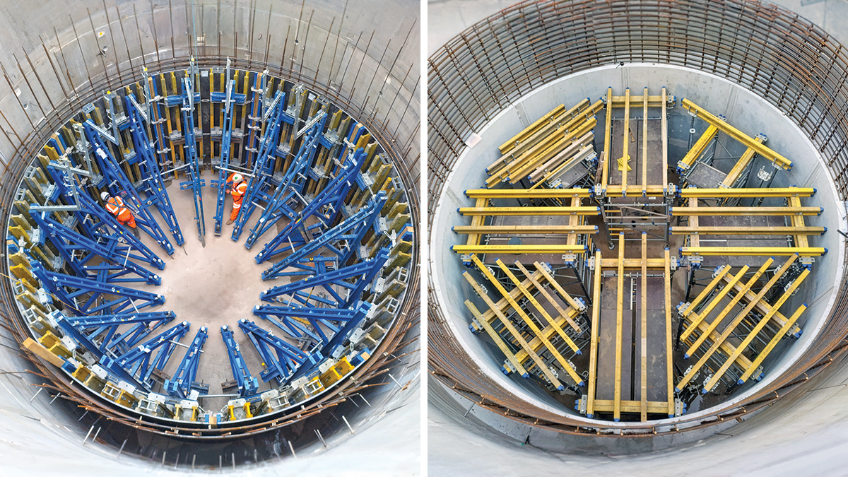
Great Ayton STW: (left) Formwork for first pour of RC liner and (right) temporary works to secure platform for 2nd pour of RC liner - Courtesy of Esh Stantec
To meet AMP7 Water Industry National Environment Programme (WINEP) requirements, Northumbrian Water appointed Esh Stantec to deliver a programme to increase storm tank capacity at several sewage treatment works. The scope and delivery of the projects were strongly influenced by Environment Agency regulatory deadlines. The works comprised a range of solutions, including buried in situ and precast reinforced concrete tanks, caisson shafts, and reuse of existing assets. Across a four-year period, Esh Stantec progressed six projects from concept design through to detailed design and construction, delivering a combined additional storm storage volume of 590m3 with an estimated programme value of £10m.
This article focuses on two contrasting schemes at Greatham STW in Hartlepool and Great Ayton STW in North Yorkshire, with particular emphasis on Great Ayton, where a constrained site and unlikely ground conditions required a collaborative and adaptive construction response.
Greatham STW
At Greatham STW, the scope was to provide an additional 55m3 of storm capacity. In parallel, the Greatham Wetlands Project was also progressing, driven by requirements for nitrogen removal and habitat creation. This created an opportunity to coordinate more closely across project teams and identify efficiencies for the client at an early stage.
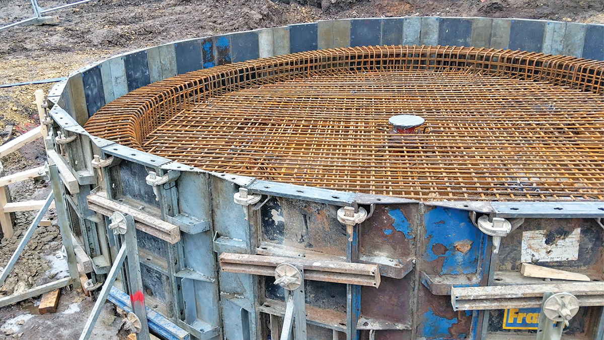
Rebar for the base of the Greatham STW above-ground tank – Courtesy of Esh Stantec
With the future wetlands project in mind, optioneering for the storm tank project initially focused on several forms of short asset life storage solutions, to reduce CAPEX and carbon. For example, a pillow/bladder tank was proposed, as commonly used in the agricultural industry. However, this was ultimately discounted due to its unsuitability for providing the settled storm storage required by the Environment Agency.
As such, the selected solution was an above-ground glass-coated steel tank from Balmoral Tanks Ltd, which provided the required volume within a compact footprint, could be installed relatively quickly, and could be re-purposed as a detention tank for the future wetlands project. A high-level radial weir and central combined inlet/outlet arrangement were used on the storm tank to promote even flow distribution and settlement, with the system operating completely under gravity to minimise operational complexity, power demand, and whole-life cost and carbon.
In collaboration with the Greatham Wetlands team, data collection requests were aligned to avoid duplication and improve the value of early survey and site information for both projects. The layout was also developed to protect future pipe corridors, accommodate changes in forecast flows, and allow simpler future pipework connections, reducing the likelihood of abortive works for Northumbrian Water as the wider site strategy progressed.
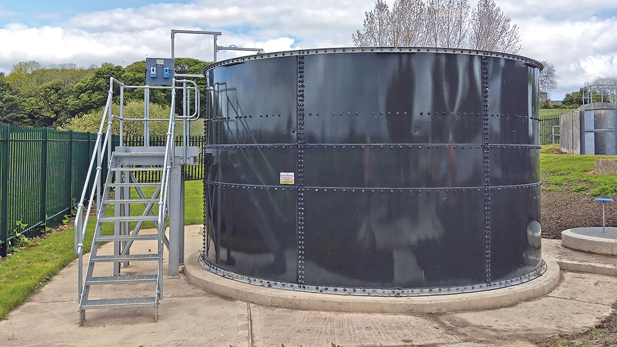
Completed Greatham STW storm tank – Courtesy of Esh Stantec
Great Ayton STW
At Great Ayton STW, the original requirement was to provide 317m3 of additional settled storm storage, later increased to 321m3 during delivery. The site was heavily constrained by existing treatment assets, buried services, and geotechnical risk, all of which influenced the chosen solution.
Optioneering considered an above-ground tank with pumped feed, a buried reinforced concrete tank, and a deep shaft solution. The pumped option was discounted because it introduced reliance on mechanical plant at the inlet works and increased the risk of screen blinding, blockage, and power resilience issues during storm conditions. A shallow buried tank required a larger footprint, greater excavation, and more disruption. The preferred solution was therefore a precast concrete caisson shaft, where the required volume could be provided vertically within a constrained area.
A key element of the civil design was the new inlet and overflow pipework to the shaft. Early definition design identified a pinch point between existing DN500 surface water drains, other buried services, and the trickling filters, which were considered sensitive to settlement. This area was treated as a significant risk, and therefore data collection focused here to define viable pipeline corridors. The original arrangement of separate gravity inlet and overflow pipes was ultimately rationalised into a combined inlet/overflow pipe, reducing excavation, simplifying the shaft tie-in, and lowering service conflict risk while still satisfying the settled storm performance requirement.
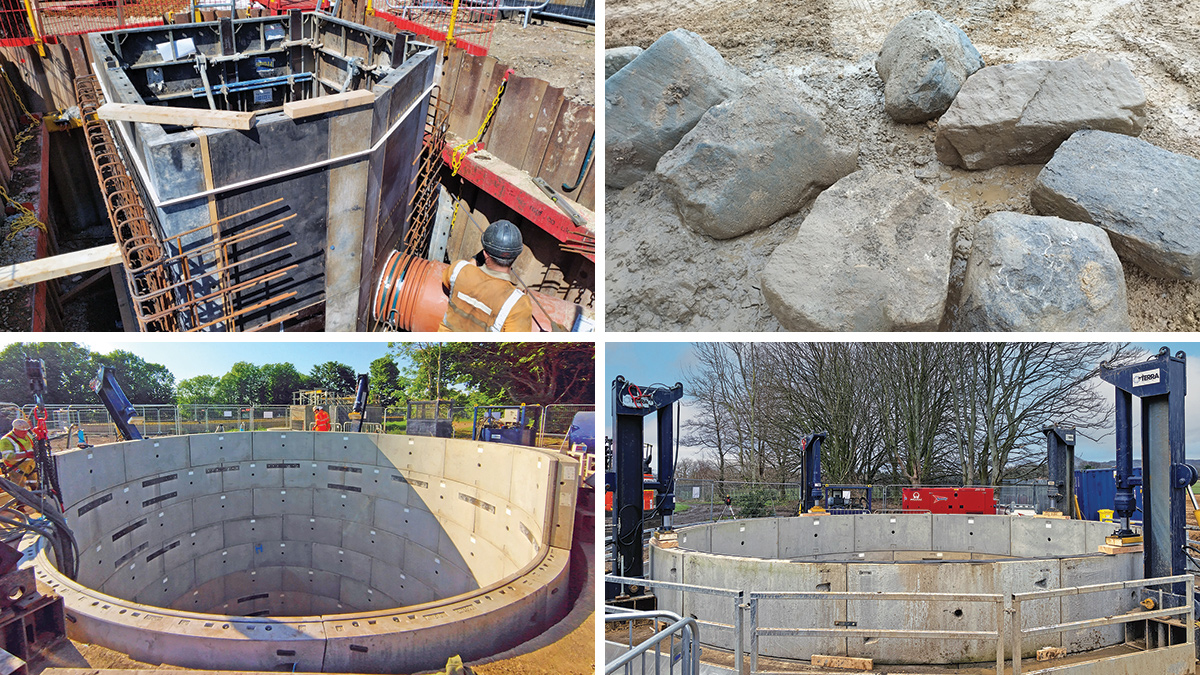
Great Ayton STW: (top left) formwork and rebar for inlet interception chamber, (top right) group of boulders removed from shaft, (bottom left) precast concrete segmental ring building, and (bottom right) shaft construction with jacking system engaged – Courtesy of Esh Stantec
Northumbrian Water WINEP Storm Tank Programme: Supply chain – key participants
- Principal Designer & Principal Contractor: Esh Stantec
- Specialist shaft designer: COWI
- Ground investigation: Ian Farmer Associates
- Temporary works: JC Consulting
- Temporary works: MGF Ltd
- MEICA: Retroflo Ltd
- Shaft & tunnelling contractor: Terra Solutions Ltd
- Shaft formwork: Doka
- Core drilling: A19 Drilling Limited
- PCC shaft segments: FP McCann Ltd
- Systems Integration: IDEC Group Ltd – Aureos
- Temporary dewatering: Project Dewatering
- Temporary overpumping: United Rentals
- Water treatment plant: Siltbuster Group
- OSMA UltraRib structured wall pipework: Wavin
- Glass-coated steel tank: Balmoral Tanks Ltd
- Ductile iron pipework: Saint Gobain PAM UK
- Modular pipe seal: Hauff-Technik
- Return pump: Xylem Water Solutions
- Metalwork fabrications: ADL Fabrications
- Asbestos removal: Lucion Environmental Ltd
- Rebar/reinforcements: Midland Steel
Shaft construction
Following main contract award, Esh Stantec appointed Terra Solutions Ltd as the specialist shaft contractor, with COWI UK Limited acting as specialist shaft designer. Construction of the shaft began in January 2025.
Ground investigation identified granular strata with groundwater encountered in upper and lower horizons, with monitored levels typically between about 1.7m and 2.5m below ground level. Given the groundwater table and sensitivity of nearby structures to drawdown, the shaft was designed to be sunk using a wet caisson methodology rather than a dry excavation with extensive dewatering.
The caisson method relied on maintaining water balance within the shaft as excavation progressed, allowing internal water pressure to counter surrounding groundwater and reduce the risk of basal instability or piping. Precast concrete rings were built progressively at surface level and sunk using a reinforced concrete collar and jacking system.
The intended sequence was to reach formation, place an underwater concrete plug to resist flotation, sump pump internally, and then construct the reinforced concrete base slab and benching. This approach avoided dependence on an abstraction licence and reduced the risk of settlement to adjacent assets.
Shaft ovality issue & resolution
During shaft sinking, much larger cobbles and boulders were encountered than had been indicated by the pre-construction ground investigation. At around 5m below ground level, these obstructions prevented further shaft sinking. Material was found underneath the cutting edge and larger particles were also believed to be bearing against the external face of the shaft lining.
Once the main obstruction had been removed and sinking resumed, the uneven resistance, caused by remaining material on the outside of the shaft, was considered to have initiated ovalisation in the lower shaft rings, which became visually apparent following further sinking and dewatering.
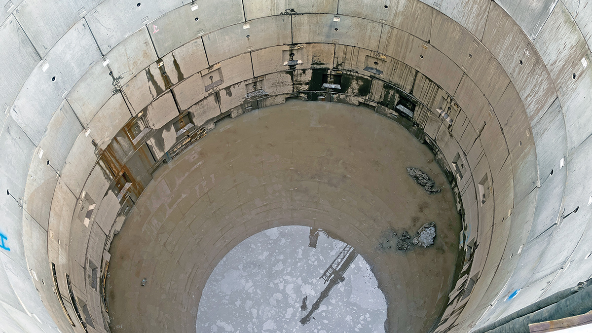
Great Ayton STW: Ovality first observed – Courtesy of Esh Stantec
The situation was managed through a highly collaborative response, with close coordination between the principal contractor, specialist shaft contractor, designer and temporary dewatering contractors, with safety and asset protection treated with critical importance. External dewatering, which had previously been avoided because of settlement and permitting concerns, was introduced on a controlled temporary basis to allow inspection and obstruction removal, supported by settlement monitoring of nearby structures.
Laser scanning was then used to quantify the shaft geometry and confirm the degree of ovality. Rather than abandon the shaft, the team worked through a series of design and construction reviews to develop a recoverable solution that maintained the required storage volume while reducing residual risk.
This included:
- Revising the shaft from the original 13-ring arrangement to an 11-ring shaft with part of the storage volume recovered below the cutting ring within the plug zone.
- The internal base and benching arrangement were modified to reduce concrete volume to free up more storage volume.
- Pouring the stabilising plug underwater to maintain positive pressure inside the shaft.
- Designing and installing a fixed diameter in situ reinforced concrete structural liner, acting as an independent structure to the shaft. The upper three rings were demonstrated to remain structurally stable without secondary lining, preserving useful storage volume. Pouring was complete in stages.
- Dewatering was then used in a tightly controlled manner to empty the shaft and install the liner before being removed as soon as practicable to limit further ground movement.
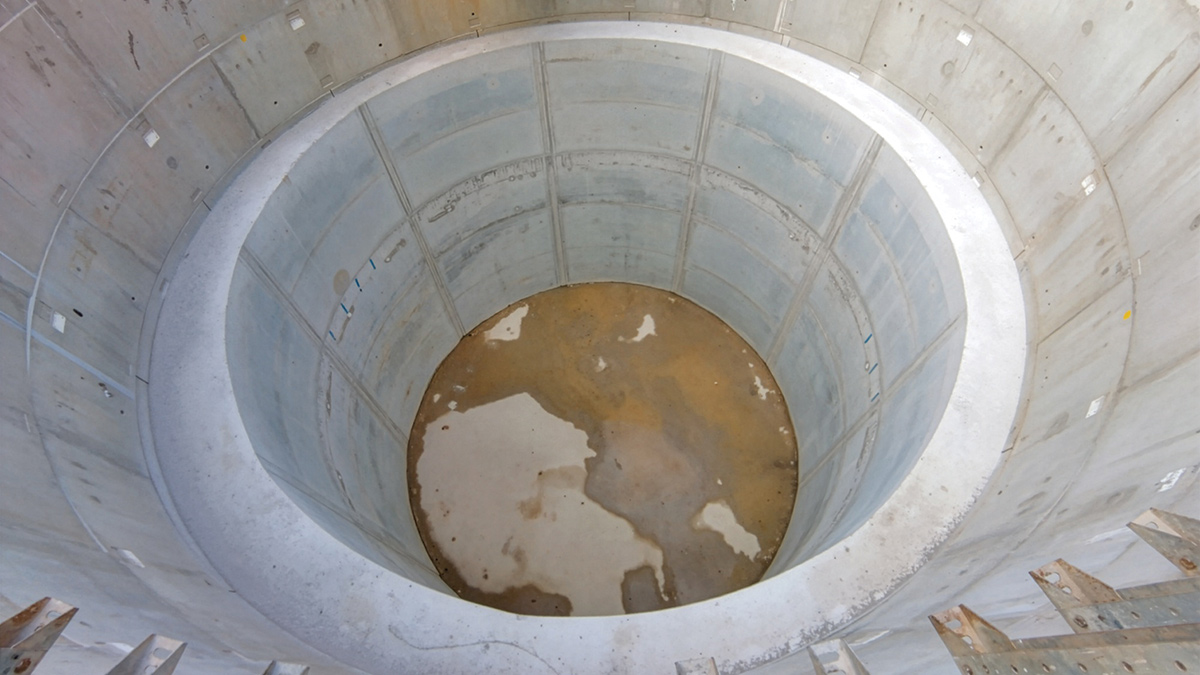
Great Ayton STW: RC liner works complete – Courtesy of Esh Stantec
The Great Ayton Storm Tank Project showed both the value and the limitation of pre-construction information on a constrained operational site. The ovality issue became one of the defining challenges of the project, and its resolution depended on close collaboration between contractor, designer and client teams to understand the risk, adapt the design and complete the asset safely.
Pipe penetrations
At Great Ayton, Hauff-Technik GKD modular seals were adopted for selected pipe penetrations through the shaft wall to provide a more controlled watertight detail than traditional grout arrangements. This also reduced installation risk around circular penetrations and time spent working from height. This was a particularly suitable application for the combined inlet/overflow pipe.
This product was trialled here as an innovative approach and has since been proposed as a more standard solution across the Esh Stantec joint venture for similar applications. Note, the detail was not considered acceptable for the rising main penetration due to the potential thrust forces generated during pressure testing.
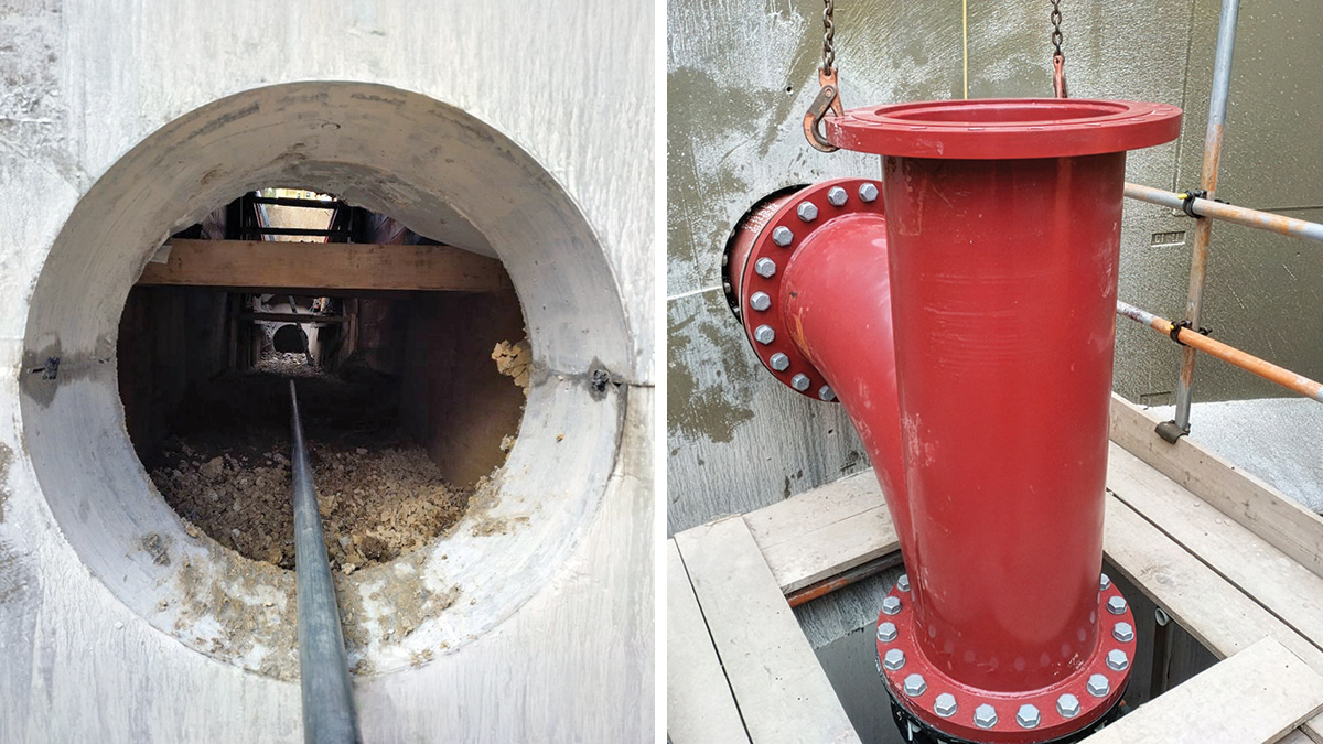
Great Ayton STW: (left) 600mm core through shaft wall and (right) DN500 inlet/overflow pipe, with modular seal installed – Courtesy of Esh Stantec
Conclusion
The WINEP Storm Tank Programme showed that storm storage delivery on operational wastewater sites requires solutions tailored to site-specific constraints rather than a single standard approach. Greatham provided a compact and efficient above-ground solution, while Great Ayton required a deep shaft and a carefully managed redesign during construction in response to unlikely ground conditions. In particular, the resolution of the shaft ovality issue demonstrated the importance of collaborative working and adaptive engineering in reducing risk and achieving a compliant final asset for Northumbrian Water.
Crucially, all works were completed in time to meet the regulatory deadlines and secure the AMP7 WINEP output, with additional storm storage delivered through solutions matched to operational need, buildability, and long-term performance.