Harthill Reservoir (2024)
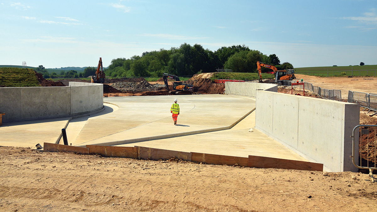
New spillway construction with embankment breach in progress in the background - Courtesy of Canal & River Trust
Harthill Reservoir near Sheffield, was built in 1796 to supply water to the Chesterfield Canal and is operated by the Canal & River Trust, the UK’s largest canal charity. It has a capacity of 295,045m3. The reservoir is a popular commercial fishery owned by the Canal & River Trust and the Rotherham Sailing Club is based at the reservoir, with a car park at the east edge of the dam. The Yorkshire Outdoor Swimmers Club has a licence for swimming, kayaking and use of a rescue boat in the reservoir. In January 2020, in accordance with the Reservoirs Act 1975, a Section 10 inspection identified the need to upgrade the reservoir’s spillways to increase its resilience for extreme flood events. A new spillway was to be constructed at the western end of the reservoir dam, replacing the function of the previous spillways.
Reservoir’s history
Harthill Reservoir was originally a cascade of three reservoirs constructed between 1771 and 1796 to provide water supply to the Chesterfield Canal. Two of the three reservoirs were later joined together to form Harthill Reservoir, fed by the smaller Harthill Old Reservoir and the upstream Pebley Reservoir.
Harthill Reservoir has a single earth-fill embankment dam at its northern end, 440m long and 9.2m high. The dam crest is 3m wide and carries a stone pathed public footpath. There is a curved concrete wave wall running along the upstream face of the embankment crest. The underlying geology is Middle and Lower Coal Measures, comprising sequences of coal, mudstone, seatearths and sandstones.
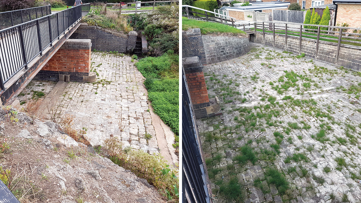
(left) Original primary spillway prior to decommissioning. New heritage-approved brickwork will be used to match existing red and blue imperial brickwork of bridge abutments and central support pier and (right) the original downstream masonry apron of the primary spillway. The apron is being retained to allow for seepage through the new rear wall, embankment and garden drainage. Improved access for future maintenance will be added via a new galvanised steel footbridge and stairs to the rear of the apron – Courtesy of Kier
Existing spillways
The reservoir had two spillways; the original masonry spillway at the east mitre of the dam at a level of 101.38mAOD; and a larger 45m auxiliary concrete spillway in the middle of the reservoir dam at 102.13mAOD, built in 1961. It also had two draw-off pipes that went through the dam and into valve tunnels, which were used to control the feed to the Chesterfield Canal. The upper level outlet was near the eastern end of the dam with an invert level of approximately 99.34mAOD, and the lower level outlet was to the west of the auxiliary spillway, with an invert level of approximately 95.30mAOD.
Both spillways emptied into the Broadbridge Dyke Feeder channel that runs into a culvert under Woodall Lane, and on to the Chesterfield Canal, two miles away at Kiveton Park.
The 2020 S10 report determined the spillways did not meet modern reservoir standards, identifying the potential for hidden erosion of the auxiliary spillway, as well as a lack of capacity in the culvert and potential for deterioration of the masonry on the main spillway. The upstream face of the spillway had evidence of erosion.
Planning
Local people and stakeholders were consulted and plans were submitted to Rotherham Metropolitan Borough Council, including a construction environmental management plan and a construction traffic management plan.
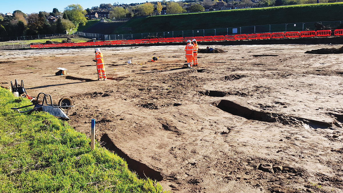
Archaeological investigation undertaken prior to start of main works. Full footprint of planned works plus 10m easement either side was investigated for historical materials – Courtesy of Kier
Construction constraints
A range of geotechnical investigations and topographic surveys were carried out, as well as heritage, archaeological and ecological assessments.
Harthill Reservoir is mainly surrounded by agricultural land and woodland, but the village of Harthill is close to the dam, so disturbance during the works needed to be minimised. There are public footpaths around the perimeter of the reservoir, through its car park and across the dam crest.
The reservoir is designated a non-statutory Country Wildlife Site. Arcadis carried out an ecological appraisal of the site, with surveys for protected and notable species, including bats, birds, reptiles, amphibians and badgers.
The project aims to deliver in excess of 10% Biodiversity Net Gain (BNG). To compensate for the removal of short stretches of hedgerow and a section of semi-natural woodland, new trees, hedgerow, broad-leaved woodland and grassland will be planted, and new bird and bat boxes and a hibernaculum will be installed.
Other measures to compensate for the disruption to wildlife included:
- Pre-construction nesting bird checks.
- The removal of refugia under supervision by an Ecological Clerk of Works.
- Lighting design to minimise light spill.
- Providing ramps to enable trapped animals to escape from incomplete excavations.
There are no statutory heritage designations, but the Canal & River Trust considers all historic structures to have heritage value, in particular the draw-off tunnels and original spillway.
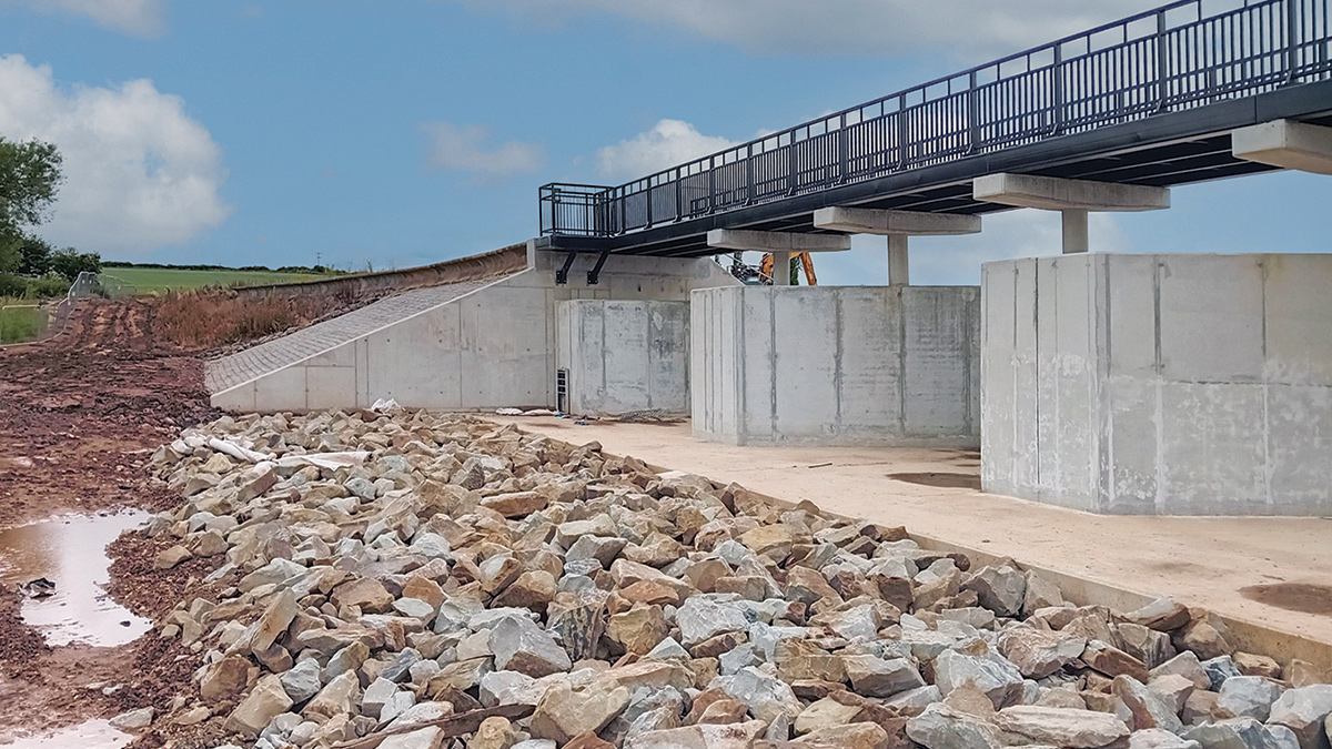
Footbridge over newly built spillway and riprap erosion protection upstream of concrete apron and labyrinth weir – Courtesy of Kier
Harthill Reservoir: Supply chain – key participants
- CRT framework partner/principal contractor: Kier Group
- Designers: Arcadis Consulting (UK) Ltd
- Construction delivery partner: AE Yates Group
- Flood studies & modelling scenarios & ecological appraisals: Arcadis Consulting (UK) Ltd
- Fish rescue & welfare: MEM Fisheries Consultants & Services Ltd
- HDPE pipe: AE Yates Directional Drilling
- Sewer cleaning, CCTV & drainage: OnSite Central Ltd
- RC concrete works: FAB Formwork & Reinforcement
- Precast concrete: Moore Concrete Products Ltd
- Flow controls: Aquiko
- Penstocks: Aquatic Control Engineering Ltd
- Steelwork/new spillway footbridge: Ekspan
- Handrailing & access steps: PA Welding Ltd
- ArmorLoc blocks: RPC Contracts Ltd
- Drainage & manhole chambers: Burdens
- Steel reinforcement: Express Reinforcements Ltd
- Concrete: Right Mix Concrete Ltd
- Imported aggregates: Rotherham Sand & Gravels
- Imported aggregates: JA Jacksons
- Plant hire: Buckhurst
Draw-downs
Ahead of the works, both Harthill and Pebley Reservoirs were drawn-down and Arcadis prepared a detailed flood study, modelling scenarios for water levels and rainfall events during the works.
Harthill Reservoir was completely drained ahead of construction works. A specialist contractor rescued the fish ahead of the full draw-down and they were re-homed elsewhere on the Canal & River Trust’s network. Pebley Reservoir continued to be held at 1.5m below the top water level to provide attenuation and some water supply to the canal. Harthill Old Reservoir was slightly lowered.
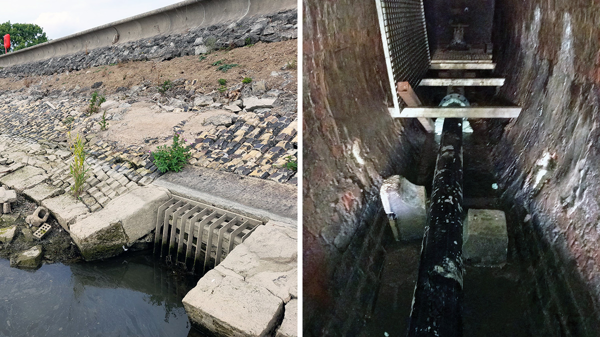
The original upper draw-off inlet has been discontinued by grouting up the inlet and full pipe running through the embankment and (right) lower draw-off pipe and guard valve in the access tunnel within the reservoir embankment – Courtesy of Kier
New spillway design
Following a review of the potential options, the team concluded building a new spillway was the best way forward. The auxiliary spillway was located at the tallest part of the dam where failure could release the entire volume of the reservoir. The channel downstream of the original spillway was insufficient to convey ordinary floods and posed a risk to the houses close to the right-hand of the bank.
The new spillway has been built on the left-hand abutment of the dam where the embankment has limited height and where it could be built on natural ground, reducing the risk of failure due to erosion under the concrete slabs. It takes over the function of the two previous spillways and the design aims to avoid the dam overtopping, taking into account the potential effects of climate change.
The new spillway was constructed from reinforced concrete grade C32/40, with an exposure class of XD2 providing a design life of 100 years. All reinforcement is 60mm (including +10mm tolerance) and is high yield strength, fyk = 500N/mm2. The concrete has been designed in line with water retaining structures standards.
The design does not alter the flood risk downstream, keeping outflows in line with the previous configuration.
The new spillway has been designed to comprise a two stage labyrinth weir with lower slots, where the slots are equivalent to the original primary spillway, and the remaining weir length is equivalent to the auxiliary spillway.
A labyrinth weir with three sections was chosen in place of a straight-axis weir to minimise the width of the breach through the dam, reducing the amount of concrete and excavation required for construction. Minimising the width also limited the span of the new bridge crossing the new spillway and the channel width downstream of the weir.
The weir has three lower sections acting as a weir at 101.38 mAOD, two penstocks and two low flow pipes for canal supply. The top of the weir crest is at 102.13 mAOD.
The feeder flows are contained within two low-flow channels positioned along the sides of the spillway, so it can be inspected whilst the feeder flow is operating. They carry the low flows from the penstocks, providing improvements to emergency drawdown capacity.
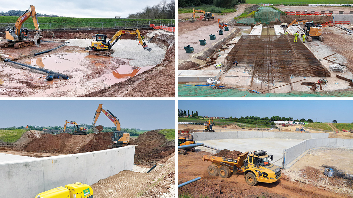
(top left) Underslab drainage with clean aggregate layer being installed prior to new spillway slab construction, (top right) : fixing of steel reinforcement within the spillway base beneath the position of the new labyrinth weir. Steelwork and concrete of this section of base slab is tied into a 1.4m deep concrete cut off/shear key tying into the bedrock below, (bottom left) breaching of the reservoir embankment commenced once downstream sections of the new spillway were in place and all necessary approvals were gained, and (bottom right) New spillway construction during embankment breach – Courtesy of Kier and Canal & River Trust
Movement and contraction joints
There are several movement and contraction joints across the spillway, with a central longitudinal joint. The joints were designed to meet new Environment Agency (2021) guidance for spillways, with drainage pipes beneath.
The majority of the movement and contraction joints were positioned to align with joints in the structure. But there is a single movement joint within a section of curved wall that does not align with a joint, allowing for the large section of curved wall. The contraction joints in the weir do not pass into the slab. This allowed the weir to be constructed in stages, so sections could be operational during any flood events experienced during construction.
Spillway freeboard
The wall heights of the spillway section were built to best suit the required freeboard. Downstream of the labyrinth weir, where the flow transforms from super-critical to sub-critical, the walls have their maximum elevation (the same as the dam crest) and therefore a very large freeboard (>2m). The USBR formula was used to assess a suitable freeboard. Calculations using the preliminary results from CFD analysis provided values between 600 and 700mm, which was easily accommodated in the design. This method double-counted waves and splash, but compensated for the lack of knowledge about spray, and provided additional protection against uncertainties (from modelling, hydrology, climate uncertainty).
The spillway approach walls extend out past the embankment. Reinforcement continues between the wingwalls and the base slab, so the approach walls act integrally with the other structural elements.
Spillway discharge channel
The spillway discharge channel conveys flows along the existing ground contours until the channel bed is higher than natural ground. It has a mild slope and is routed away from the embankment along the natural contours, to further improve the embankment resilience and reduce the amount of excavation required.
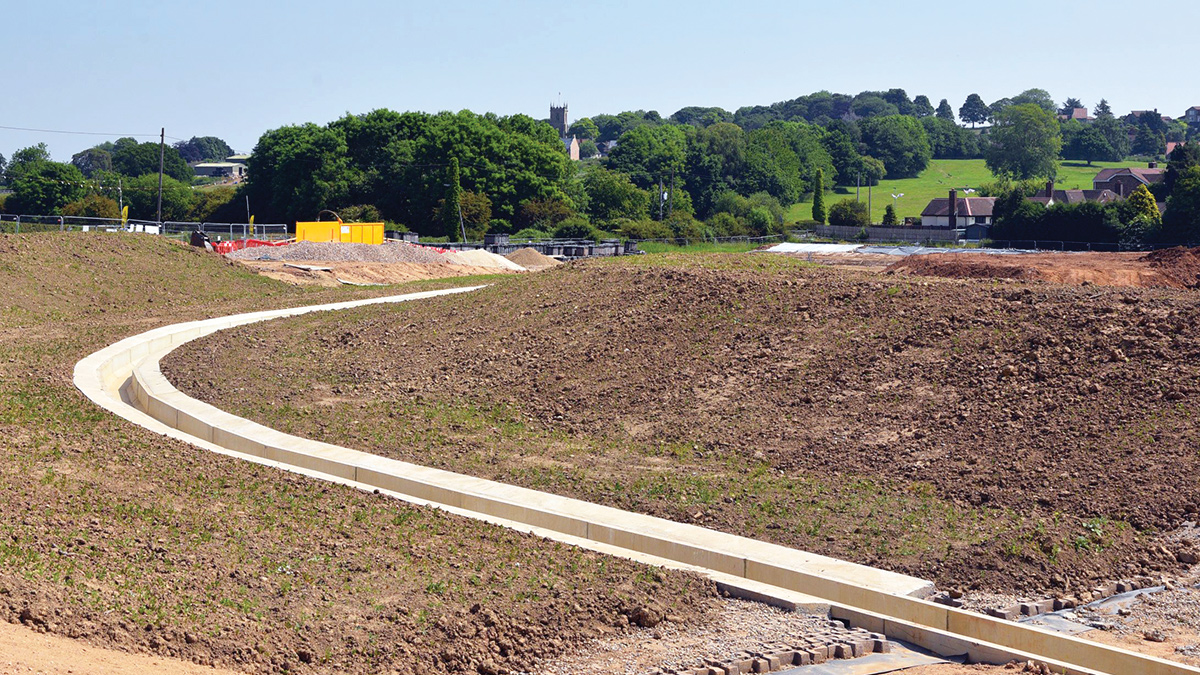
Spillway discharge channel linking the new spillway to the existing culvert via a drop shaft – Courtesy of Canal & River Trust
The natural hillside slopes down from left to right. At the end of the bend the channel shallows with decreasing embankment heights before passing down a shallow channel. This section of the spillway is away from the dam and has less effect on its safety, so the discharge channel was designed to have a softer, greener engineering approach than the spillway.
The discharge channel terminates at a new drop shaft positioned over the existing culvert. This connects the lower draw-off tunnel to the Chesterfield Canal feeder.
Drainage
A new drainage system of perforated pipes runs beneath the new spillway, to monitor any potential leakage through the construction joints and drain groundwater. They exit the spillway through a drainage junction with an inspection chamber and manhole. A land drain carries flows from the connection manhole to a new outfall on the southern side of the spillway channel.
A new perforated drainage pipe runs along the toe of the dam from the right-hand side of the new spillway to the right-hand side of the auxiliary spillway. The primary spillway channel drains the rest of the dam. A new channel was built to take water from the new spillway to the existing culvert under Woodall Lane.
The ditch running along the toe of the main embankment was formalised using a French drain to prevent water from ponding at the toe of the dam, protecting it from erosion.
A separate drainage pipe runs along the access track on the western and northern side of the spillway, collecting water from the field and road.
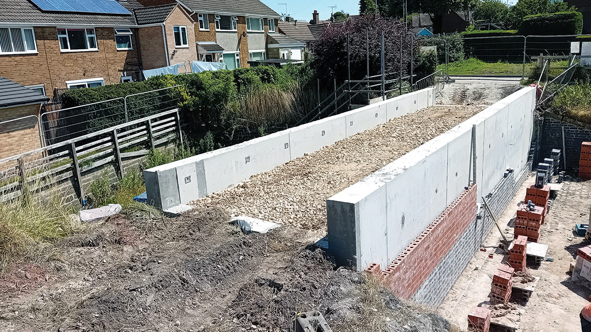
Decommissioning the original primary spillway with double concrete walled structure with fascia to match original spillway – Courtesy of Kier
Decommissioning the old spillways
The 1960s concrete spillway in the middle of the dam was removed, and an earth-filled section of embankment was reinstated. The upstream face of the dam was covered in Armorloc erosion protection blocks. The section of wave wall removed was replaced with a new handrail.
The original masonry spillway was blocked off with a U-shaped reinforced concrete wall, clad with heritage-approved bricks matching those from the original heritage structure. The base slab includes a 700mm cut-off keying into the formation layer of the original spillway. New handrails and footpath surfacing will provide safe access across the new structure. The timber footbridge crossing the original spillway is being replaced with a new 1m wide galvanised steel footbridge, with gated steps down to the channel on each side for access/maintenance. The bridge is designed for a live load of 5kN/m2.
The original upper draw-off has been discontinued by infilling the pipework and inlet with non-shrink grout. The original lower draw-off has been investigated by remote CCTV equipment, cleaned using ultra high pressure jetting and relined with a new HDPE pipe. The existing downstream control valve has been reused and a new upstream control valve has been fitted at the inlet within the reservoir. This will have an actuator fitted to be controlled hydraulically from a GRP cabinet on the reservoir crest.
Access & water control
The footpath above the dam was resurfaced and a new 30.6m long and 3.5m wide steel footbridge was installed across the new spillway. It has a deck level of 103.9m AOD and 1.4m high handrails. The bridge deck has 12mm thick anti-slip panels and is designed to support 5kN/m2.
The two new drawdown penstocks are controlled from an enclosed lockable section on the new bridge. New access steps and footpaths will be created for reservoir maintenance work.
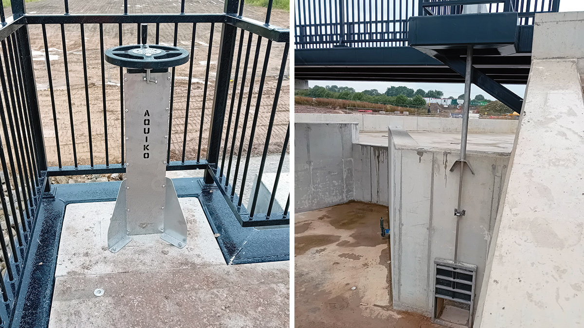
(left) Access and water control for the reservoir team to operate the penstocks within the new labyrinth weir. The wheel is lockable to prevent unauthorised use and (right) One of two control penstocks located within the labyrinth weir, viewed from upstream. Control headstock located above with access from the spillway footbridge – Courtesy of Kier
Conclusion
Steps were taken to minimise the amount of excavation and concrete required for the construction, reducing disturbance to local residents and the landscape, while maximising flood resilience. Unfortunately, the winter of 2023/24 was the wettest on record and caused significant delays to the project.
At the time of writing (July 2024), the spillway is nearing completion and the reservoir will start to be re-filled in late August/early September. Harthill Reservoir is now better placed to withstand the weather events brought about by our changing climate, minimising the risk of local flooding while continuing to supply the Chesterfield Canal with water for navigation, and provide a valuable public amenity for local people and wildlife.


