Melbourne WTW – Clarification & Coagulation (2018)
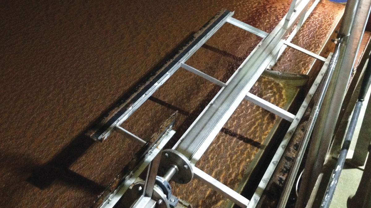
Optimised trial with water successfully reaching the scraper beach - Courtesy of Stantec Treatment
Melbourne WTW is the second largest clean water treatment works in Severn Trent Water (STW) and serves large population centres in south Derbyshire and Leicestershire with capability to supply up to a maximum of 250Ml/d. The dissolved air flotation (DAF) process removes suspended solids and other contaminants via the use of air bubble flotation. The clarification and coagulation (C&C) project will replace the existing flight and chain DAF scraper system, which currently suffers from regular failures, with a more mechanically robust and reliable beach scraper system
Background
The Severn Trent Water PR14 business plan focused on increasing asset performance to drive serviceability, reliability and resilience on their water treatment works. Melbourne WTW was built in 1996 and designed to process a maximum flow of 250MLD. Utilising a DAF plant for its raw water clarification process, Melbourne WTW has been identified as requiring investment on its clarification and coagulation process and particularly the DAF plant scraper mechanism.
The DAF process removes suspended solids and other contaminants via the use of air bubble flotation. Air is dissolved into water which is then released from solution, producing micro bubbles which then come into contact with the solids and contaminants within the raw water. These bubbles attach to the solids and float them to the surface where they collect as a sludge and are mechanically scraped and removed from the tank, with the clarified water flowing out of the bottom of the tank.
DAF systems can utilise a number of mechanical systems to skim the floating sludge from the tank, the system currently operated at Melbourne is a flight and chain system. This system has two drive shafts located at opposite ends of the tank. A chain with paddles attached is then rotated around the two drives, the paddles on the underside then push the sludge blanket forward into the sludge outlet channel.
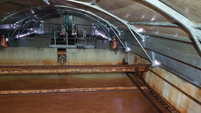
Existing flight and chain scraper – Courtesy of MWH Treatment
The Melbourne flight and chain scraper system fails on a regular basis due to chain breakages and paddle connection failures which results in the chain and the paddles dropping into the tank. To repair the system, the DAF cell has to be removed from service to allow the repairs to be completed.
An alternative system to flight and chain scrapers are beach scrapers. Beach type scraper systems are proven as mechanically reliable; however, process design parameters recommend that beach type scrapers should be used only on cells up to a maximum length of 7m. Although the Melbourne length is longer at 7.6m, Stantec Treatment (now MWH Treatment) supported the decision to challenge this design parameter, and Severn Trent Water agreed to a trial on one of the Melbourne cells.
Design risk mitigation
To manage the risk of installing the trial scraper system, Stantec Treatment developed a beach and scraper design that could be integrated onto existing support bearing housings and connected to the existing drive mechanism ensuring that, should the trial be unsuccessful, the original system could be reinstalled with minimal effort or disruption.
Measures of success
To support evaluating the performance of the new scraper mechanism (to be trialled on cell ‘K’), STW process design engineers set the following performance criteria:
- The turbidity of the clarified water outlet of cell ‘K’ shall be consistently lower than or equal to the combined clarified turbidity at Melbourne.
- The alarm level for the combined clarified turbidity at Melbourne is 2 NTU. The target turbidity for the clarification process is 1-1.2 NTU. Turbidity is expected to remain below 1.5 NTU during normal operation.
- During stable operation, if trial cell ‘K’ performance drives the combined clarified turbidity to exceed 2 NTU for a period of 20 minutes, the trial will automatically fail.
- During stable operation, the daily average cell ‘K’ clarified water outlet turbidity is not to exceed the daily average cell ‘A’ clarified turbidity by more than 25%.
In addition to the clarified water process performance, additional success criteria included:
- No significant change in the consistency and % dry solids content of sludge from the trial DAF cell ‘K’ to that of the non-modified cells.
- Following initial optimisation, successful operation of the trial scraper for a continuous period of 4 weeks without mechanical failure or maintenance requirements.
Trial optimisation
The trial plant was installed with an initial physical arrangement. Through the trial optimisation stages, modifications were made including lowering the beach level and increasing the length of the scraper blades. This enabled water levels overlapping onto the beach over the full range of flows.
Following STW approval, DAF cell ‘K’ was returned to service and allowed to remain in service with the turbidity data being monitored. The cell remained in service for a week before a decision was made to carry out further modifications to the scraper blades. There was concern that the sludge blanket thickness was building up due to the scraper speed not removing sufficient sludge from the process.
PDE trial site visit
Working with Severn Trent Water, the following concerns were raised regarding the beach scraper trial:
- Sludge float layer thickness was being compacted by the beach presenting a risk of sludge layer knock down
- No white water was visible at the saturator inlet end of the tank.
- Sludge feeding through the centre of the cell due to the sludge float layer friction on the wall.
To address these concerns, the scraper mechanism was modified to add an additional scraper blade at 180° to the first blade.
At this time the performance criteria was amended to the performance of cell ‘K’ to be within two standard deviations of all cells. As only cell ‘K’ and ‘A’ has individual turbidity instrumentation installed at that time.
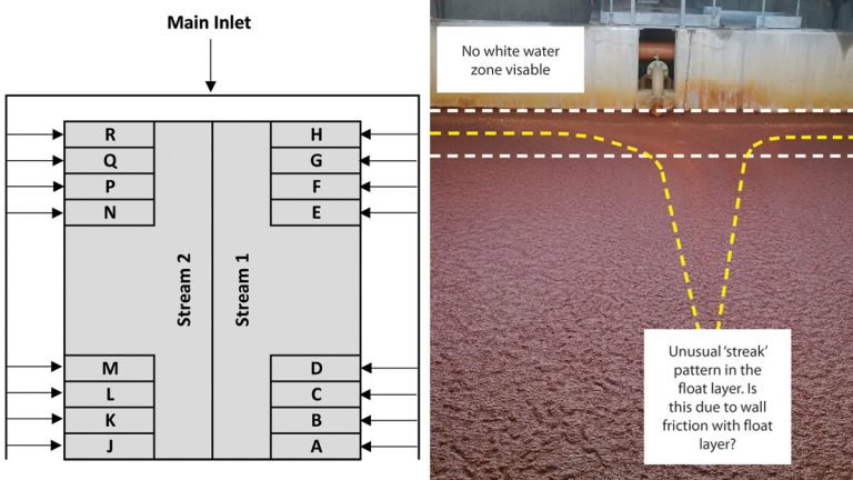
(left) Melbourne DAF cell layout – Courtesy of MWH Treatment and (right) optimisation trial cell ‘K’ – Courtesy of Severn Trent Water
Full trial
Following the modifications and reinstallation of the scraper, cell ‘K’ was returned to service. It was immediately evident that the increase in the number of blades had reduced the sludge float layer thickness and the decision was made to allow the scraper trial to commence into the 4-week trial. (Cell ‘K’ remained in service for the 4-week requirement).
Four week trial and manual sampling
Over the 4-week trial period, manual sampling showed a difference in turbidity performance between the two Melbourne DAF streams, with the turbidity level from Stream 1 being consistently lower than the levels being achieved by Stream 2. As a result, the turbidity instrument from cell ‘A’ (Stream 1) was relocated to cell ‘J’ (Stream 2) and performance measures adjusted accordingly.

Additional scraper blade was added to increase sludge removal – Courtesy of MWH Treatment
Performance summary
Trial performance outputs were:
- Trial turbidity results from cell ‘K’ range from 1.3-1.38 NTU against the combined water at Melbourne consistently operates at around 1.2-1.3 NTU. Although trial averages were slightly higher than the combined, it was agreed that the performance measure was passed due to the sampled and measured performance difference between Streams 1 and 2.
- The combined turbidity level remained below both the Melbourne alarm level of 2 NTU and the expected performance of 1.5 NTU for the duration of the trial.
- The sludge density level reduced significantly below the density level of level from an existing cell. This is caused by the temporary scraper system rubber blade sealing against the beach when scraping sludge from the cell resulting in water being trapped and scraped over the beach. The permanent design was adjusted to include blade clearance between the beach surface and the blade edge to prevent water being trapped. The sludge density will be optimised during commissioning of the new scraper system.
- Asset availability of 100% was achieved both for the 4-week trial period and in the intervening period from November 2016 to May 2018. A review of the trial has led to further improvements over the trial equipment with the permanent installation increasing resilience further through including a centre and outer support bearings, the plastic drive chain and gears replaced with new metallic chain and drive gears and the motor sized to allow the desludge scraper speed to be optimised.
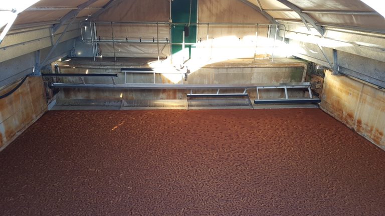
Completed new scraper mechanism back in service – Courtesy of MWH Treatment
Based on the trial, STW approved the proposal to proceed with the design and build of the new beach type scraper system within all 16 (No.) of the Melbourne DAF cells. The proposal was approved, design was completed and installation of the new scraper system has been completed across all of the Melbourne DAF cells.
Commissioning is scheduled to take place between March 2018 and September 2018. The current turbidity levels on the Melbourne DAF cells indicate that the new system has been successful in achieving the effectiveness of control risk and serviceability requirements for the site.


