Monmouthshire & Brecon Canal Restoration Project (2018)
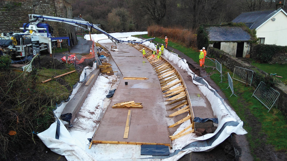
View showing canal cross section - Courtesy of Arcadis
The Monmouthshire & Brecon (M&B) Canal is constructed on an embankment, with the village of Llangattock directly below in the Brecon Beacons National Park in Powys, Wales. The canal is picturesque with the backdrop of a Grade 2 listed lime kiln and passing over the watercourse, Nant Onnau via a large aqueduct. The canal was constructed through unfavourable ground conditions and locally sourced material over much of its length and is prone to considerable leakage. Significant repair works that have been carried out over the years to attempt to resolve the leakage issues however, none of the implemented solutions had been able to provide a permanent fix.
Feasibility study
Canal & River Trust requested that a feasibility study was undertaken to investigate the most suitable option to address the ongoing leakage problems and mitigate future expensive reactive repair works. The options considered during feasibility included soil mixing, puddle clay lining, reinforced concrete channel, geomembrane-based canal lining systems and geo-synthetic clay liners (GCLs). The feasibility reviewed the design life of 120 years to ensure that a high performing lining solution was implemented. A geomembrane-based canal lining system (PVC) was recommended for the restoration works. This solution offered the lowest cost, highest seepage/leakage reduction and long-term durability.
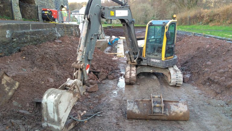
Excavation in front of the lime kilns – Courtesy of Arcadis
Proposed works
The proposed canal restoration works at Llangattock covered a 650m length. The works were to add resilience to the infrastructure of the canal, securing its embankments, reducing water demand and making its habitats bigger, better and better connected.
The project was funded with £2.538m from the Welsh Government’s Green Infrastructure Capital Grant. General relining works included:
- Installing a PVC liner protected with 125mm concrete.
- Constructing waterway walls from reclaimed masonry, concrete blockwork, reinforced concrete and porcupine blocks.
- Installing a 300mm diameter plastic bed drain under the channel and rodding eyes at approximately 100m centres.
- Installing stop planks to the bed drainage discharge chamber.
- Constructing a canoe portage and steps.
- Abandoning culvert MB-032-027.
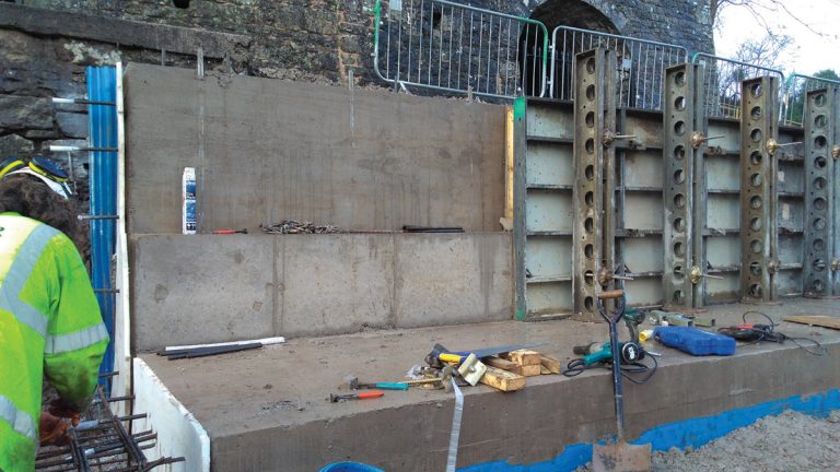
Reinforced concrete wall construction – Courtesy of Arcadis
Detailed design
In detailed design the following investigations were undertaken to support design:
- Silt sampling.
- Topographical survey.
- Hydrographic survey.
- Tree survey.
- Phase 1 habitat survey.
- Microphyte survey.
- Ground investigation.
Following investigations, a decision was made to remove silt on the canal bed to allow preparation of the bed at the appropriate navigable depth. A decision was also taken to rebuild the waterway walls (over the section of canal to be relined) so that watertight integrity could be guaranteed.
The waterway walls were in a poor condition (cracks, missing mortar, missing bricks etc) with no visible footings. The PVC liner would be laid on a prepared canal bed and taken under the foundations of the new waterway walls and up the back of the walls to near ground level. The liner would be placed in an anchor trench at the top behind the wall. Soil backfill would be placed in the trench to provide resistance against pull out. Bed drainage was proposed to reduce groundwater pressure on the new PVC lining. The bed drainage was to be connected to a sluice chamber which discharged to a watercourse.
The design proposal included retaining the waterway wall in front of the lime kilns (Grade II listed building) and connecting the existing wall and the new wall with dowels. However, during excavation the wall in front of the lime kiln was undermined and it partially collapsed. Following consultation with Canal & River Trusts’ heritage advisor, a new reinforced concrete wall with stone cladding (matching the existing in type, colour and texture) was designed and constructed to support the access road and lime kilns above it.
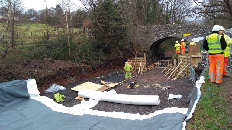
PVC liner installation on prepared canal bed – Courtesy of Arcadis
The reinforced concrete wall (1.8m height and 30m long) and canoe portage access steps were designed to the following standards:
- BS 8110-1-1997 – Structural use of Concrete.
- BS 8002-1994 – Earth Retaining Structures.
- BS 8004-1986 – Foundations.
Wallip software was used to prepare the ground model, wall sizing (masonry and reinforced concrete walls) and to undertake stability checks. The Reinforced Concrete Council spreadsheet was used for the structural design of the reinforced concrete wall and the overall factor of safety for sliding and overturning was greater than 1.5.
Arcadis proposed the sequence and methods to be used for the installation and jointing of the liner, installation of the concrete protection layer, jointing to waterway walls and formation of the offside verge features.
Construction
Construction, installation and jointing of the liner was carried out by experienced, skilled operatives recommended by the manufacturer and approved by CRT. Lining sheets was carefully laid out on the prepared formation free of sharp objects, ruts, protrusions, voids and undulations.
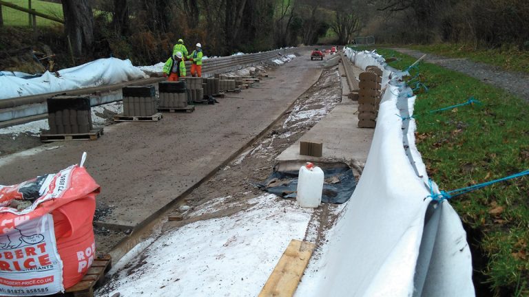
Concrete protection to PVC liner – Courtesy of Arcadis
The contractor tested each joint and repaired any that were found to be faulty. Through the main channel invert and on the side slopes, the lining was protected by a 125mm thick layer of mass concrete.
On completion of all lining works and immediately prior to re-filling the canal with water, the concrete protection layer and side slope protection were carefully inspected to ensure that there were no cracks or depressions which may have threatened the integrity of the liner.
It was important to ensure that there was a fully water tight joint between the new lining membrane and existing masonry walls/new concrete or other surfaces. For joining a PVC lining membrane to new concrete surfaces, a backstop water bar was cast into the face of the wall for the liner to be heat/thermally welded.
For joining a PVC lining membrane to an existing masonry wall or other existing structure, a concrete ground beam was cast against the face of the structure, connected by resin fixed dowel bars and including two strips of Hyrdotite CJ water stop running along the beam/wall joint. A backstop water bar was then cast into the outer face of the ground beam for the liner to be heat welded.
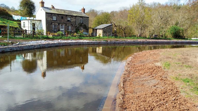
View showing refilled canal – Courtesy of Arcadis
Whilst draining down the canal silt was discharged into watercourse (pollution incident). NRW requested for the sluice valve to be regulated to control the speed of dewatering.
Improvements to the sluice discharge chamber included the installation of stop plank grooves with removable planks. This enabled canal drain-down to be from the top of the water column thus providing greater capacity to manage and avoid the risk of excess canal silt being discharged with the canal water.
Reference was made to CRT guidelines for best practice in the design of stop planks and the TRADA Calculator was used for the design of timber stop planks to be installed in front of a discharge chamber.
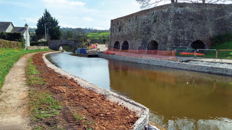
View showing completed works – Courtesy of Arcadis
Summary
The Monmouthshire and Brecon Canal is the most popular attraction in the Brecon Beacons National Park. The canal restoration project ensured that the many local businesses, active travel routes, leisure activities, regeneration projects and habitats that currently depend on the canal could continue to thrive and grow.
In addition, significant environmental improvements saw:
- Over 23,000 plants planted.
- 362 hazel stools coppiced.
- 3.5km of hedgerow gapped and diversified.
- 4.6km of riparian edge improved.


