Northcombe WTW GAC Scheme (2018)
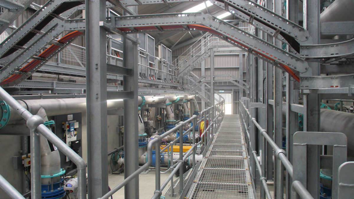
Completed GAC gallery - Courtesy of SWW Delivery Alliance H5O
Located near Okehampton, Northcombe WTW supplies a large region of North Devon including Barnstaple, Bideford and South Molton. The works supplies over 88,000 customers, with around half of these relying on Northcombe as their sole supply of water. As standards for water quality change, South West water (SWW) has been issued a notice by the DWI to mitigate the risks of trihalomethanes, other disinfection products and pesticides in treated water. Installation of a new GAC plant was decided upon, and as tier 1 contractors in H5O for AMP6, Interserve Construction Ltd (ICL) was awarded the contract. Beginning in October 2016, the £6.3m project is due for completion in June 2018. The scheme was designed by Arcadis and constructed by ICL in conjunction with various Tier 2 suppliers from the alliance.
Overview of existing process
Designed for a maximum output of 50Ml/d, the works was constructed in 1995 and is fed from the nearby Roadford Lake via a raw water pumping station. Once at the works, flow is split between 10 (No.) FloFilter dissolved air flotation and filtration (DAFF) tanks. After collection in a common outlet channel, an interstage pumping station (IPS) pumps flow into a splitter chamber which divides the water between four secondary filters. The secondary filters then flow into a contact tank with a baffled section before entering the final water reservoir.
Project drivers
South West Water (SWW) has several long-term objectives to increase water quality throughout the region. The Northcombe specific goals are:
- A 25% reduction in total trihalomethanes (TTHMs) in the final treated water.
- Reduce zonal TTHMs to a screening value under 50μg /l annualised average.
- Comply with individual and total pesticide standards.
- A final treated water Cl residual value of below 0.5mg /l.
- Reduce future risk of a water quality event involving either Geosmin or MIB affecting either taste or odour of final water.
The existing process (relating to the above) involves dosing powdered activated carbon at the front end (prior to the DAFF). The installation of 6 (No.) new granular activated carbon (GAC) contactors was decided to be the most effective long-term solution to meet the above goals.
Northcombe WTW actively supplies a large catchment area. It was therefore crucial to install and commission the new GAC plant whilst causing the minimum disruption possible to the existing process. This was guaranteed by collaborative working and production of detailed process risk assessments, which highlighted key precautions and methodologies needed to protect the treatment process.
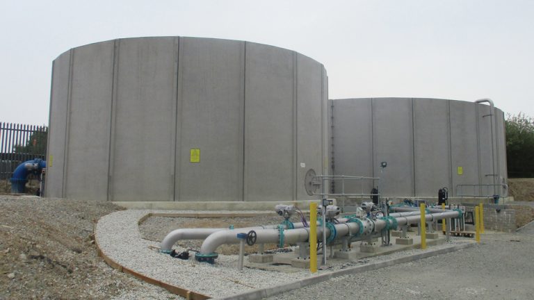
GAC dirty wash water and Regen tanks – Courtesy of SWW Delivery Alliance H5O
Design and installation
Due to the complex surface chemistry of granular activated carbon (GAC), installation of a new GAC plant was the obvious choice to provide the improved water quality SWW want to produce.
The installation of a new GAC plant and building required integration into the existing process. The GAC plant required installation of dedicated motor control centre (MCC), air blower, clean backwash tank (CBT), dirty wash water (DWW) tank and a Regen tank.
New installations required to cope with the overall, upgraded process (including GAC) included new low voltage distribution board (LVDB), picket fence sludge thickener and associated dosing pumps.
Throughout the project, there was a constant drive to deliver the highest quality product whilst frequently reviewing the design. The teams’ extensive prior experience with GAC projects allowed many aspects of the design to be altered, either to improve the process or to reduce cost or program. This was evident from the start. Upon looking at the design for the new CBT which used 500mm pipework for the overflow, an opportunity was identified.
The team had a lot of 450mm pipe left over from the previous project (also a GAC installation), and so went to the designers, requesting some alterations to allow the spare 450mm pipe to be used up. This is testament to the teams’ attitude throughout the project, making smart choices to improve the finished product.
It was necessary to install a GAC bypass to aid with commissioning; this allowed the GAC plant to take progressively larger portions of the works flow, minimising the impact of the new process on consumers. This bypass had to be able to cope with the whole works flow initially, requiring a large section of 700mm pipe. To maximise space in the GAC building, the decision was made to run the pipe out of the building. This made sense, especially as the bypass leg is redundant with the GAC fully online.
Installing the new GAC plant between the DAFF and secondary filters required the existing chemical dosing to be relocated and a new static mixer to be installed.
Due to the age of the old set up, there was no protection around the dosing point. The team was of the view this was not acceptable, so went above and beyond the design specification, installing not only new dosing lances and isolation, but also a custom-built Perspex safety case. This resulted in a safer and more easily maintained chemical dosing system for the works.
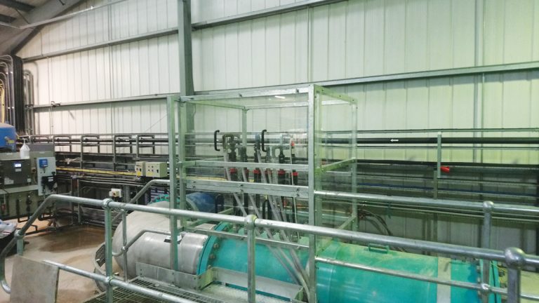
Chemical dosing guard – Courtesy of SWW Delivery Alliance H5O
LVDB
In order to feed both the existing and new items of plant, it was necessary to upgrade the site power supply. The installation of a new LVDB required isolation of the power supply into the site transformer, whilst running the plant on a generator. To minimise risk to the process, a backup generator was on site.
GAC contactors
As the fifth GAC project undertaken by H5O, the team built on extensive prior experience to improve the project. As before, off site manufacturing and precast concrete was used to ensure smooth progression and increased safety during on-site installation, providing obvious benefits.
Prior to this project, the team had already provided major improvements to the GAC installations. Providing cell man way doors, under bed drains and wash down hose reels (negating the need for above contactor walkways) are all improvements from prior projects which were implemented here. To allow the cells to be emptied quickly the under-bed drainage was sent to the existing inlet works overflow. Again, this pipework was left over from prior projects, giving an extremely cost-effective drainage solution.
New improvements for this job include a sample and observation point for the GAC outlet channel and a dedicated media loading system and pump. This pump proved to be extremely useful throughout the commissioning process and was used to test a variety of pipework and tanks.
The contactors were slotted into the existing process, between the DAFF and the pre-secondary filters splitter chamber. Prior to GAC installation, process water from the DAFF tanks flowed to an interstage pumping station (IPS), which pumped flow into the splitter chamber. Investigation showed that these pumps were capable of delivering water up to the new GAC plant (located at a higher elevation than the splitter), allowing post GAC process water to gravitate down to the splitter, rejoining the existing process.
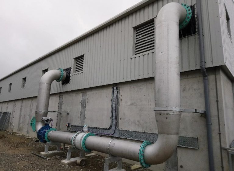
External GAC bypass – Courtesy of SWW Delivery Alliance H5O
The GAC plant bypass allowed the team to break into the existing IPS and divert flows up to the GAC (before commissioning the plant), through the bypass and onto the existing process with minimal disruption. The bypass contained a flow control valve, which was used during commissioning to gradually divert flow into the contactors.
The GAC plant contains 6 (No.) contactors. Each individual cell is capable of treating 13.1Ml/d, meaning that the plant can provide the correct contact time for the works maximum flow (52Ml/d) with only 4 (No.) contactors online. This allows for one to be out of service and one to be in wash at the same time. Each contactor has an empty bed volume (EBV) of 109m3 giving a total contact volume of 654m3. As the GAC plant is only acting as a contactor for adsorption of organics, a media grade of 12/40 was chosen.
Northcombe WTW GAC Scheme: Key Participants
- Client: South West Water
- Principle contractor: Interserve Construction Ltd
- Designers: Arcadis
- Electrical sub-contractor: Bridges Electrical Engineers Ltd
- Engineering sub-contractor: Alpha Plus Ltd
- Engineering sub-contractor: Minear
- Precast concrete: Carlow Precast Concrete (now FLI Precast Solutions)
- Tank installation: A-Consult Ltd
- Tank installation: DD Engineering Ltd
- Air blowers: Aerzen Machines
- Pumps: Grundfos
- Valves: Industrial Valves
- Actuators: Rotork
- Water quality monitors: Swan Analytical UK Ltd
- GAC building framework: MPK Steelwork & Cladding Ltd
Clean backwash tank (CBT) and backwash system
To prevent any interference with the existing filter washing, it was necessary to provide the GAC with its own source of wash water. To minimise disruption to the flow of process water, a clean backwash tank was installed.
This could be slowly filled from a take-off on the process flow prior to the GAC plant. The tank is sufficient size for two backwashes without refilling (880m3). Two new VFD clean backwash pumps (duty/standby) supplied by Grundfos have been installed; allowing a maximum backwash bed expansion of 30%.
A dedicated air scour blower has also been installed, delivering a maximum air flow rate of 1453Nm3/hr. As air scour washes are not critical to the GAC plant, and only carried out during around one in ten backwashes, it was not necessary to install duty/standby blowers.
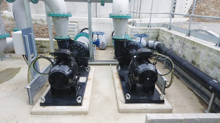
Clean backwash pumps – Courtesy of SWW Delivery Alliance H5O
Dirty wash water system
To cope with the increase in waste wash water due to GAC washing and rinsing, it was necessary to provide a new GAC DWW tank, Regen tank and sludge thickener.
The normal route for GAC wash and rinse water is into the GAC DWW tank. This tank also takes all final supernatant from the works, before returning the mixed supernatant/GAC wash water to the head of the works. If wash water from the GAC is deemed to be of such poor quality it cannot be returned to the head of the works, it can be diverted into the Regen tank. From here, it is sent through the sludge system for treatment.
In the event of poor quality water being deposited into the GAC DWW tank, there is an option to return supernatant from the thickeners directly to the head of the works. Not only does this provide a path for the treatment of the poor quality water in the GAC DWW, but also allows the filters to keep washing and the process to continue.
The DWW tank is 1025m3 and the Regen tank is 442m3.
Sludge system
The current sludge system was found to be unable to cope with the increased loading, caused by the new GAC plant and associated wash system. To allow the works to comfortably deal with all dirty wash water, a second sludge thickener was installed. To save on cost and minimise the complexity of the upgraded system, the existing system was duplicated.
Once online, the existing DWW tank was set up to feed both the new and existing thickeners equally. This allowed the polymer dosing to be copied exactly from the existing system, meaning only one batch of polymer need be made up for both systems. The design called for installation a new drop pot for the polymer dosing, but as ever the team were keen to streamline the project. Investigation yielded an opportunity to connect the new poly pumps to the existing pumps drop pot, saving both time and space.
Conclusion
At the time of writing (May 2018), the project is in the very final stages of completion. All commissioning is complete; the GAC and sludge plant have been running for two months. On site in general, landscaping is coming to an end, and over 95% of the identified snags have been addressed. The project team has been recognised for outstanding work in a number of areas. The constant drive to operate in a safe manner was highlighted when we were recently given Interserve Construction’s safety award.
The team also won South West Water’s Pure Award for pure water. This award was given for an innovative water saving method developed and employed by the core Northcombe team during media loading and the early stages of GAC plant commissioning and is indicative of the values held by both Interserve and SWW regarding sustainability.


