
Rivelin WTW – Sirofloc Replacement: Part 1 (2016)
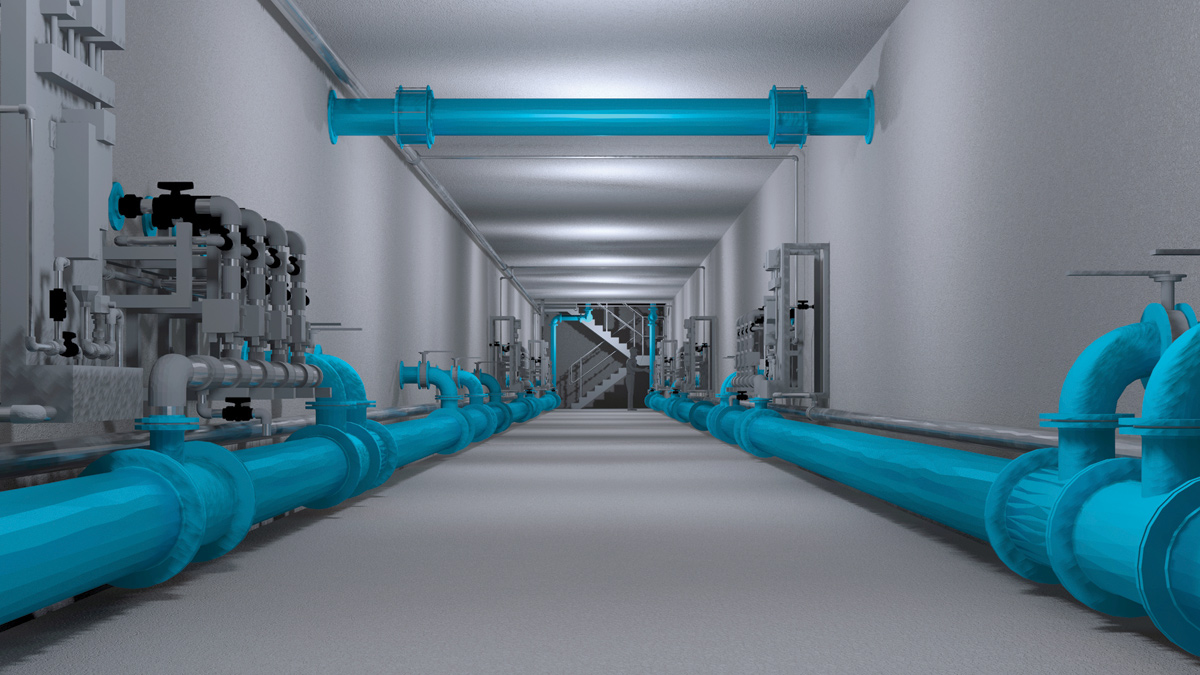
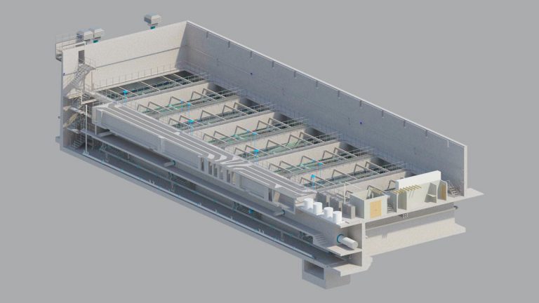
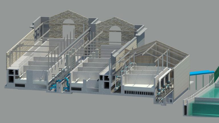
3D model of clarifiers sludge gallery - Courtesy of Mott MacDonald Bentley Ltd
Rivelin WTW provides drinking water for a population of approximately 200,000 in Sheffield. The raw water feeding the works is a blend of water from the Derwent Valley via Ladybower Reservoir and the local catchment via Rivelin Reservoir. The quality of the raw water has deteriorated in the period since the current plant was built in the early 1990s; therefore investment was needed to ensure the treatment works would continue to reliably process the high colour in the raw water coming into the site. The existing first stage of treatment is based on a Sirofloc process. This is a metal-ion coagulation process utilising magnetite which is a single source supply providing a further risk to the continued operation of the works. Yorkshire Water has committed to a solution which replaces the Sirofloc process and improvements to other parts of the works. The £24m scheme delivered by Mott MacDonald Bentley (MMB) will ensure that the works can operate at its full output under all predicted raw water conditions.
Scheme constrains
Yorkshire Water has committed to the Drinking Water Inspectorate (DWI) a compliance date for beneficial completion of the new clarification process on site of 31 December 2017. Some of the water network fed by the works can only be fed from the Rivelin works, limiting the time period for which the works can be shut down and therefore increasing the criticality of the works.
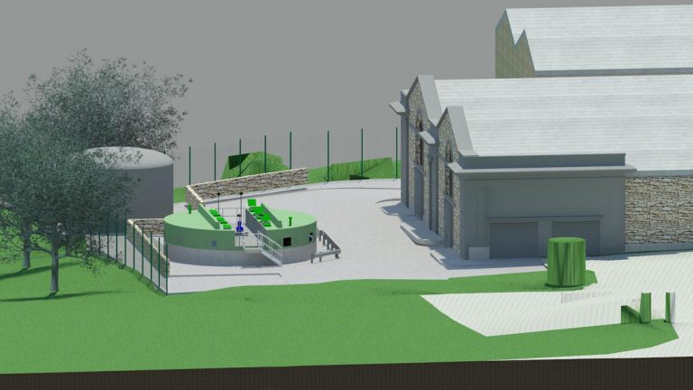
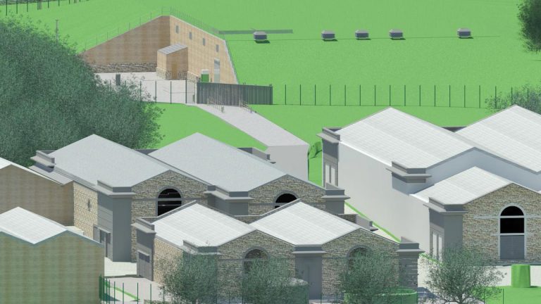
The works is located in the Rivelin Valley to the West of Sheffield on the boarder of the Peak District National Park. Given this highly sensitive location, the planning process, which would need Secretary of State approval, was seen as major risk to the scheme. The programme required that planning had to be approved at the first attempt in order to meet the compliance date. Two options were considered for the new facility, the first being a new building above ground, and the second, a below ground option which would be backfilled and seeded upon completion. Following extensive consultation with key stakeholders including Nick Clegg MP, local councillors, the Rivelin Valley Conservation Group, Sheffield Wildlife Trust, Crosspool Forum and residents, the below ground option was chosen. This early engagement with as many interested groups as possible helped ensure the solution put forward for planning had the backing of the whole community.
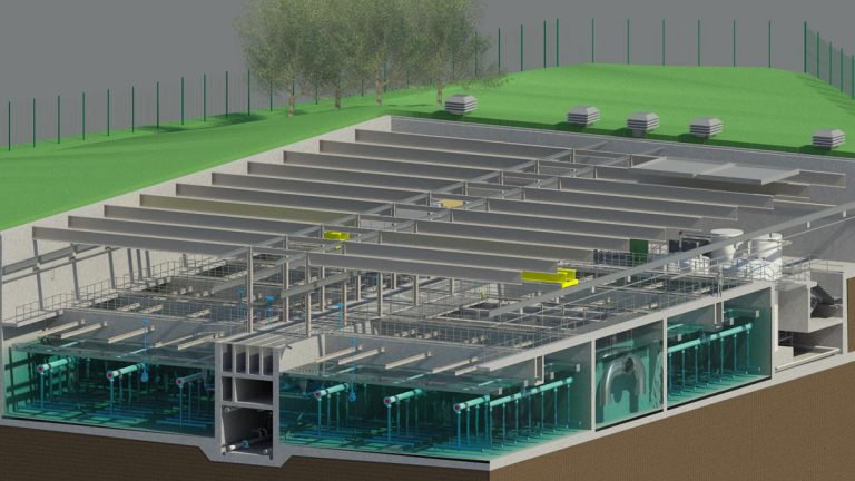
3D Model of additional sludge thickener with integral cover – Courtesy of Mott MacDonald Bentley Ltd
The existing site has limited space for construction of new facilities; however Yorkshire Water owns tenanted land adjacent to the site. The land is bisected by a large diameter local high pressure gas main limiting the area available for construction and pushing it further away from the existing site buildings. An existing footpath runs between the existing site and the land owned by Yorkshire Water. The footpath will have to remain in use throughout construction and on scheme completion.
Investigation – early contractor involvement (ECI)
Yorkshire Water appointed MMB to undertake an ECI investigation contract into the business risks present at the site in September 2014. A notional solution had been developed around a new MIEX and dissolved air flotation (DAF) first stage treatment to replace the Sirofloc process. The solution also included 6 (No.) additional RGFs to reduce overall loading rate on the RGFs to suit the new clarified water.
As part of the investigation MMB explored several options, including retention of the Sirofloc process, MIEX + dissolved air flotation, flocc blanket clarification and Veolia’s Actiflo Turbo process. MMB managed a pilot trial of Veolia’s Actiflo process along with a temporary rapid gravity filter in order to evaluate its performance treating the high colour and cold moorland water sourced from the Rivelin and Ladybower Reservoirs.
3D model of section through sludge thickener – Courtesy of Mott MacDonald Bentley Ltd
Working in conjunction with Yorkshire Water and through the use of 3D point cloud data and 3D modelling, each option was detailed to a level to allow a risk and value study and selection of the preferred solution. This study took a wholistic view of the project risks, with the decision to take forward the flocc blanket clarification process made based on suitability and robustness of the process, TOTEX, planning constraints and environmental issues.
A raw water design envelope for the new plant was developed based on past raw water data and predicted further deterioration over the next 20 years.
Solution
The selected solution consists of the following elements:
- Construction of 7 (No.) flat bottom clarifiers process plant capable of treating 83MLD of raw water within a design envelope of 0-199 Hazen and 0-20 NTU.
- Construction of 3 (No.) new rapid gravity filters as an extension to the existing filtration plant to reduce the overall RGF loading rate to 5.2m/hr.
- New service water pumps on the existing site.
- Upgrades to the washwater recovery plant capacity including the construction of an additional sludge thickener.
- Installation of safe permanent access into the existing rapid gravity filters.
- Replacement of the media in the existing rapid gravity filters.
- Improvements to the sludge to sewer mixing system.
Due to the location of the site and the necessity to achieve planning approval at the first attempt, discussions with planners and local groups took place early in the process. This consultation led to the decision to bury the clarifier structure, making it almost invisible from the surrounding hills and the footpaths of the national park.
3D model of existing works showing RGF extension and buried clarifier building in the background – Courtesy of Mott MacDonald Bentley Ltd
Value engineering
Prior to and following contract award, several value engineering sessions have been held between Yorkshire Water and MMB to ensure that the scheme is based on the most efficient and cost effective design. The scheme cost has been reduced through retaining the existing inlet works, hydro turbine and overflows, the retention of the bulk sodium hydroxide storage, the design of hydraulic flocculation, and through the extension of the existing rapid gravity filter backwash system.
Learning has been brought into the scheme from existing Yorkshire Water Assets at Embsay and Harlow Hill WTW and through early engagement with end users MMB has been able to provide the appropriate solution to Yorkshire Water’s business risks taking into account safety, cost, quality, environmental impact and fitness for purpose.
3D model of clarifier building east/west section – Courtesy of Mott MacDonald Bentley Ltd
Natural capital assessment
Yorkshire Water applied natural capital assessment to the options considered during the investigation stage. The assessment recognises that nature represents a stock of assets from which society benefits in numerous ways.
The assessment allows the options to be compared with regard to natural capital by applying a value to the impact on natural resources by the scheme. The assessment identified the following Ecosystem Services as material to this scheme: (i) global climate regulation (carbon emissions), (ii) air quality, (iii) pollination, and (iv) cultural and spiritual values (effectively ‘amenity value’).
The environmental impact of the loss of these services were compared for the baseline (existing plant), the notional solution and the selected solution.
The assessment showed that all solutions have an overall negative environmental impact, all taking resources from the environment to meet the social imperative for a reliable and safe water supply.
The final solution has the least environmental impact, with a low energy solution resulting in less carbon emissions, and the inclusion of a green roof enhancing biodiversity. From a natural capital perspective, the final solution is £3.8m better than the baseline position, and delivers at least £600,000 additional benefits over the notional solution.
BIM
The scheme will utilise BIM extensively throughout its delivery; providing a high degree of collaborative design and construction, driving project efficiencies. 3D models which were developed during the investigation stage will be further developed into detailed design and used at each milestone review, HAZOPs, HAZCONs and ALM studies.
3D model of clarifier building north/south section showing buried structure with south wall and roof removed – Courtesy of MMB Ltd
The team initiated a 3D digital cloud point survey of the existing buildings and internal pipework which will be integrated into the 3D model. The employment of BIM for the scheme has already simplified the process of client review and approval through the use of virtual tours to identify access arrangements for operation and maintenance staff.
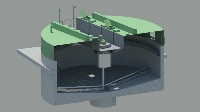
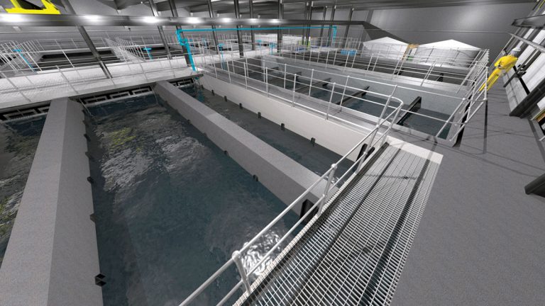
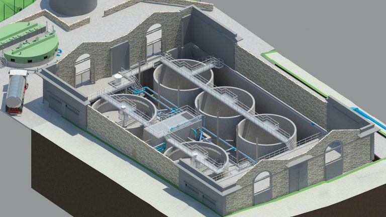
Clarifiers structure
The clarifier building will be located on land adjacent and to the west of the existing works. The 80m x 40m x 14m structure will be buried on 3½ sides to disguise its presence. Ventilation pipes emerging at the surface will be disguised as beehives and careful planting of trees will further blend the site in with the surroundings.
All of the excavated material will be retained on site to back fill the building and grade the site. The exposed section of the building providing access will only be visible from a nearby hill and will be obscured by trees. Despite this, the facade will be clad with wood to soften the impact.
The structure will comprise a concrete substructure and outer walls with steel internal columns and roof support beams.
3D model of clarifier building internal view – Courtesy of Mott MacDonald Bentley Ltd
Clarifiers design
Flow from the existing inlet works through the clarifiers and back to the existing RGF inlet channel will be by gravity. New chemical storage and dosing facilities are located within the building for dosing of sodium hydroxide, ferric sulphate and polyelectrolyte upstream of the clarifiers. The raw water is pH adjusted and ferric sulphate coagulant is dosed based on the inlet flow and raw water colour. The flow then enters flocculation lanes before being dosed with polyelectrolyte to promote formation of larger floccs.
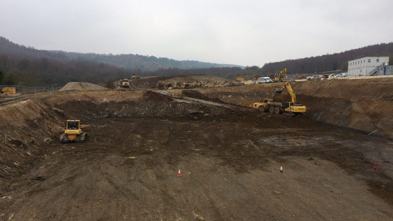
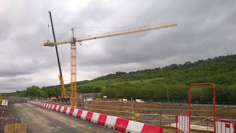
Clarifiers excavation looking West (May 2016) – Courtesy of MMB
The flow is then equally split between the in-service clarifiers. The 7 (No.) clarifiers are flat bottomed and have an up-flow between 1.7m/hr and 2.4m/hr. Each clarifier has 4 (No.) de-sludge cones discharging to a central gallery. Distribution of the inlet flow to a clarifier is delivered through 120 (No.) nozzle outlets close to the clarifier floor to achieve close to linear up-flow through the clarifier.
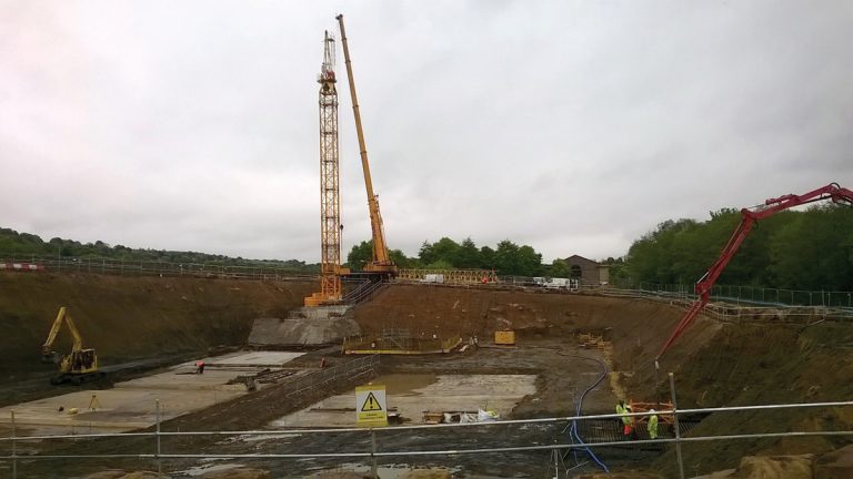
Tower Crane 1 erection looking east (May 2016) – Courtesy of MMB
The flocc forms a blanket which flows over the lip of the cones and is drawn off by gravity through de-sludge valves. Interconnecting pipework between clarifiers allows seeding of units being brought into service after cleaning.
Clarifiers construction site – Tower Crane 1 (May 2016) – Courtesy of MMB
Flow from the clarifiers inlet through the flocculation lanes and clarifier cells has been CFD modelled to confirm design parameters and allow zones showing high velocity/shear to be designed out, therefore minimising flocc break up.
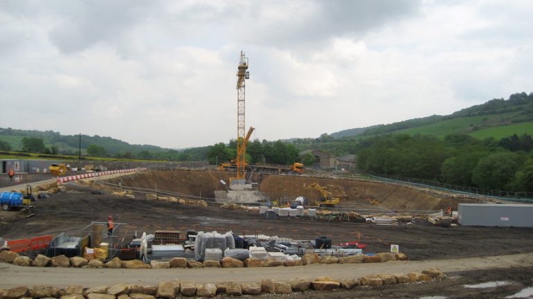
Construction works in progress on the underground clarifier structure – Courtesy of MMB
Rapid gravity filters
The 3 (No.) new RGFs are being designed to operate alongside the eight existing units; therefore the dimensions and layout will be very similar. The filters will have plenum floors with nozzles and sand/anthracite media. The high rate backwash will be increased for all RGFs to increase wash performance utilising existing pumps.
3D Model of section through existing RGF building and new extension – Courtesy of Mott MacDonald Bentley Ltd
Water recovery
Due to the increased raw water envelope and additional RGFs, the completed scheme will produce more wash water and sludge than the existing process; therefore the facilities for water recovery will be increased in capacity by uprating transfer pumps and constructing a new sludge thickener to add to the existing two units.
The new thickener will be located outside adjacent to the water recovery building. It will have an integral cover incorporating access hatches and lighting for cleaning of the launder channel and inspection of the sludge blanket. An additional polyelectrolyte dosing system and de-sludge pumps will be installed within the existing building to serve the new thickener.
Scheme progress
Planning permission was granted on the first application and there were no objections to the planned scheme. This has allowed the scheme to progress on schedule. The delivery contract was placed by Yorkshire Water with MMB in October 2015 and the scheme is currently undergoing detailed design.
3D Model of existing water recovery building with additional sludge thickener – Courtesy of Mott MacDonald Bentley Ltd
Process safety within the design has been reviewed through HAZOP studies and layers of protection (LOPA) studies. Access, lifting and maintenance studies have now been completed in the virtual environment of the 3D models allowing detailed design to progress.
- Work started on site in February 2016 on the new clarifier structure.
- Earthworks and enabling works on the new RGF extension started in May 2016.
- The clarifier site has been excavated (May 2016). Preparations are being made for casting of the base slab.
- Two tower cranes are being installed for construction of the clarifiers in late May and June 2016.
The RGFs are planned to be complete in August 2017 and the clarifiers will be in use in December 2017. Decommissioning of the redundant Sirofloc plant will start in January 2018 with overall scheme completion in August 2018.
UPDATE October 2018
Yorkshire Water and MMB published a follow up article on the progress at Rivelin WTW in UK Water Projects 2018.