
River Lyd Pumping Station (2023)
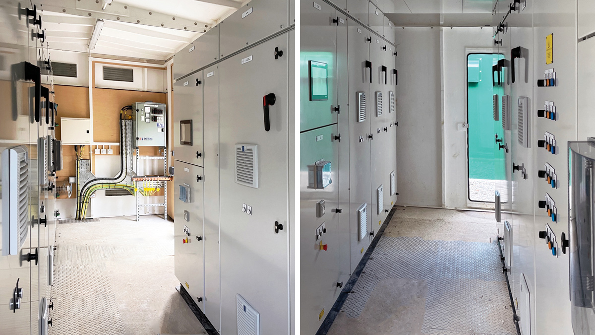
(left) LV switchgear and (right) Form 4A MCC and busbar bridge - Courtesy of Galliford Try
The River Lyd Pumping Station is consented to abstract up to 40 Mld from its intake source at Lifton, Devon during November through to March, pumping raw water approximately 7km to Roadford Reservoir. The pumping station was last used on a full operational basis during the mid-1990s and the original equipment had remained in a shutdown and non-operational state up until the point of the upgrade works. The existing electrical switchgear was deemed to be life-expired and beyond the state of any possible refurbishment. The primary driver for the scheme and the scope of works was to upgrade and re-commission the pumping station for operational use at full output design capacity. During the course of the capital works project, a temporary works scheme was implemented in order to maximise operational use of the available pump sets while the capital build was in progress.
Background
The pumping station is configured with six Pleuger-type QN borehole pumpsets supplied by Flowserve Ltd and which had been previously refurbished by the manufacturer in the intervening period, and the pumps were maintained in storage at Roadford Reservoir. Four pumps are sized at 5 Mld and two at 10 Mld, providing for a combination of flows up to 40 Mld. The discharge from the common pump manifold is to the 900mm diameter rising main to Roadford Reservoir operating with a system pressure at 11 bar.
At the works, two surge anticipation valves protect the pipeline in the event of failures and resulting critical surge conditions. Downstream of the common pump discharge manifold, and within the section of pipework that forms the washout connection at the river headwall, are two pressure transducers which have been installed to provide high pressure alarms and initiate pump stop in the event of an adverse operating condition and to afford protection to both pumps and also the rising main. From the common discharge, manifold flows leave the site through the existing 900mm rising main and are measured by a new Siemens electromagnetic flow meter installed as part of the refurbishment works.
Eel screens
Prior to the upgrade and re-commissioning works of the pumping station, a separate contract was undertaken by Galliford Try in 2021 to replace the river eel screens. The scope of works in this respect was to make the connections between each of the eel screens designed and manufactured by Andritz Ltd and a new air-burst cleaning system.
The air-burst compressed air system is a self contained package plant designed and built by Quantum Engineering Developments Ltd with its own local control panel and PLC which control the cyclical cleaning of each of the eel screens. Local alarms are initiated at the LCP and key alarms are relayed back to the main plant MCC as required. Duty/standby screw type air compressors are installed, supplying a single air receiver with operating pressure at 9 bar.
There are six air lines that connect with its respective screen and the control of air is via electro-pneumatically operated valves installed at the air compressor skid. Flexible 50Nb air hoses are installed in ducts and connect each piped outlet with a connection to the eel screen. Within the pump chamber a piped manifold of manual isolating valves and air hoses has been installed to provide for the connection to each eel screen.
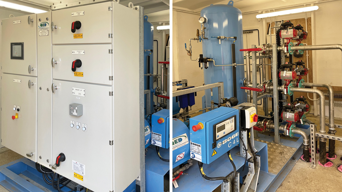
Airburst package plant – Courtesy of Galliford Try
HV & LV electrical works
The scope of HV electrical works required the re-establishment of the HV supply to the site and these works have been undertaken by National Grid to provide a new 1250 kVA supply to their existing substation on the site and inclusive of new interconnecting HV cabling from their primary substation. A new transformer of required capacity has been designed and manufactured by Wilson Power Solutions Ltd under supply to Enerveo who have completed the site HV installation.
The LV side of the transformer is connected to a new form 4A Type 3 MCC which has been designed and manufactured by Galliford Try. The build incorporates the six soft starts for each of the existing 190kW and 110kW pumpsets. The incomer is rated at 2000A and busbar 2500A. Phase failure, surge protection, and transformer protection are incorporated within the build. There are common controls section, distribution board feeders, 110V and 24V supplies. Plant control and surveillance is managed by a Schneider Electric PLC and HMI which are built within the C&I section.
Water quality monitoring
A containerised suite of raw water quality instruments has been installed in accordance with the requirements set out in South West Water’s Technical Standard for Intake Protection & Raw Water Monitoring.
The respective quality parameters measured are colour, turbidity, ph/temperature, dissolved oxygen, and ammonia. The sample is drawn from the River Lyd by a pair of duty/standby Grundfos JP sample pumps and which are connected to the river headwall by means of dedicated ducted 25Nb flexible sample pipes.
Actuated GF ball valves within the piped discharge local to the pumps allow for the sequencing of the duty/standby changeover, air scour sequence and back wash of the sample lines during the changeover cycle. Flow monitoring to the instruments is by means of inductive type flow meters. The control, monitoring, alarm initiation and operator interface is via a local control panel complete with HMI and PLC.
River Lyd Pumping Station: Supply chain: key participants
- Principal contractor & designer: Galliford Try
- Pumpsets: Flowserve Ltd
- Flow meters: Siemens
- PLCs & HMIs & switchgear: Schneider Electric
- Eel screens: Andritz Ltd
- Air-burst compressed air system: Quantum Engineering Developments Ltd
- Generators: Aggreko UK
- HV transformer: Wilson Power Solutions Ltd
- HV installation: Enerveo
- JP sample pumps: Grundfos
- Software development & automation: Galliford Try
- Rising main: Kier Group
- Instrumentation: IFM Electronic
- Instrumentation: Partech Instruments
Capital works delivery
Before any works could be undertaken, significant tree and overgrown vegetation clearance had to be carried out at the entrance to the pumping station and along the lengths of the access paths and tracks that connect with the top of the site and the existing HV substation.
GPR, topographical and ecological surveys were undertaken to establish conditions. There then followed a programme of dismantling works to remove the original GRP kiosk housing the 1990s MCC and transformer.
The programme of civil works provided for the construction of reinforced concrete bases for the new 1250kVA transformer and air-burst package plant respectively. Installed on these bases are new GRP enclosures that provide the necessary protection for this equipment. A third GRP kiosk has been installed as the enclosure for the new MCC which utilised the original constructed base slab and trench albeit extended for the larger switchgear build. Elevated concrete piers have been constructed for the container housing the raw water quality instruments and with due consideration to the known risk of flooding at the site. The new enclosures required the submission and approval of a planning application.
New ducts and drawpits have been installed to provide for the routing of pipework, HV and LV cables.
The scope of mechanical installation works principally involved the re-installation of the refurbished Pleuger pumpsets and the associated pipework connections to the existing delivery manifold and rising main; the installation of the new airburst eel screening compressor skid and its hook up requiring a new air distribution system within the pumping chamber to supply each of the individual eel screens.
The scope of the electrical installation works has been principally the uprating of the original 1000kVA supply to 1250kVA. This has required two new HV supply cables to be installed from the primary substation to the River Lyd site. A new HV transformer from Wilson Power Solutions Ltd and switchgear from Schneider Electric has been installed to make the HV connection. The new Form 4 MCC has been designed and built as the replacement switchgear incorporating the most up to date electronic components and compliance with SWW Technical Standards. The software development and automation works has been carried out by Galliford Try.
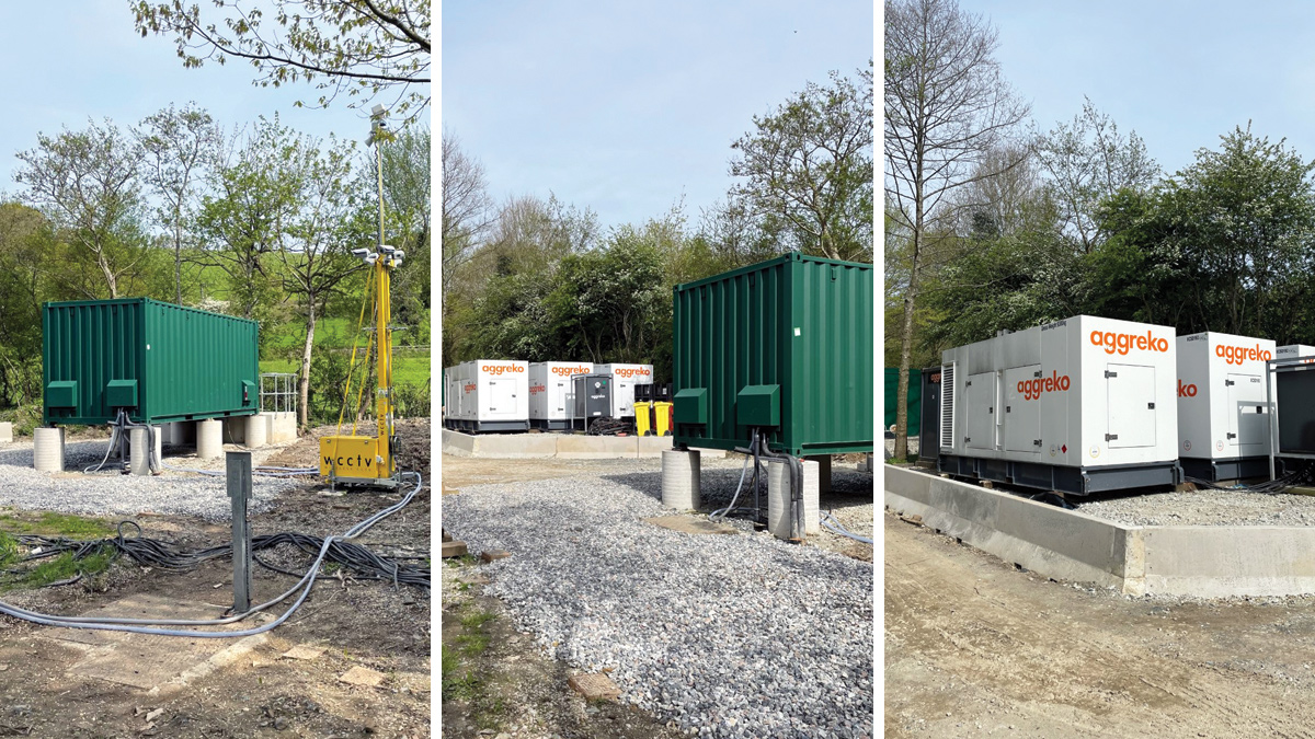
(left) River water sampling container on flood prevention supports, (middle) Aggreko UK duty, primary assist and secondary assist generators, and (right) Generator flood prevention as design by the design team – Courtesy of Galliford Try
Temporary works
During the period of the capital works build, and with continued falling level in Roadford Reservoir, Galliford Try was asked to put in place a temporary system of operation for the six installed pump sets using standby generators and temporary switchgear.
Working with Kier Group, Galliford Try took charge of the works at the pumping station and Kier Group the rising main to Roadford Reservoir, responsible for checking, filling, flushing and pressure testing the pipeline; mindful that the system was last used in 1996.
The original remit was to have the temporary plant installed and connected to allow the existing six pumps to operate by the 1 November 2022. All parties achieved their objectives, however South West Water was unable to obtain approval from the Environment Agency (abstraction permit) in the same timescale.
This did however provide more time to allow Galliford Try’s capital works team to incorporate process elements of their capital build into the temporary works (flow meter replacement, air-burst compressed air system, telemetry and online operational water quality instruments). This has provided South West Water and the Environment Agency with a more robust pumping arrangement and water quality monitoring regime.
Although the pumps and temporary works operation is scheduled to the end of March 2023, there is the possibility of an extension until the end of May 2023 which is being discussed between South West Water and the Environment Agency.
Completion
At the time of writing (April 2023) the capital works completion has been achieved insofar as it can be until such time as the temporary works operation has finished and the equipment removed off site. Following on from this, final landscaping will be completed along with those works required to complete all permanent connections to enable the pumping station to come back into operation from the beginning of November 2023.