Trosley to Beech Strategic Mains Renewals (2017)
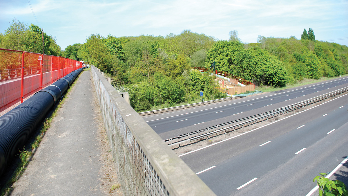
View of 450mm PE pipework within 600mm diameter rigi-duct on Ford Lane bridge: Courtesy of South East Water
In recent years there have been a number of complex bursts at the edge of the M20 motorway in Kent, where three trunk mains cross via an existing tunnel. The bursts have compromised the security of supply between South East Water’s (SEW) Trosley Pumping Station and Beech Reservoir and also flooded onto the hard shoulder of the M20 motorway. The trunk mains in question transfer, at its peak, 17.3 million litres of water to customers in West Malling, Paddock Wood and the surrounding villages. The security of these mains is therefore paramount. Pre-investigation works within the tunnel, which examined the condition of the structure and remaining design life of the existing mains, concluded that they needed replacing.
Tackling the M20
As the existing mains (one 300mm ductile iron (DI) and two 400mm DI mains) cross the M20 via a 2.1m diameter reinforced concrete tunnel, replacing them safely was problematic. Working within a confined space and next to three live high pressure pipelines was too great a risk to take. This subsequently led to the SEW integrated delivery team, consisting of SEW staff (including the Assets, Operations, Environmental, Communications and Customer Services departments) and its framework consultant Jacobs, to investigate a number of alternative cost effective and safer solutions.
The solutions explored by the team included drilling underneath the M20 with 2 (No.) 560mm OD PE100 SDR11 mains, micro-tunnelling with 2 (No.) 450mm DI insertions, and finally using a temporary large diameter overland feed. The overland feed would then facilitate the re-direction of water flow so the pipework within the tunnel could be replaced.
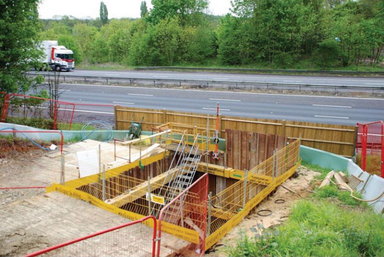
Excavation on north side of M20 for access to culvert – Courtesy of South East Water
At first, utilising directional drilling techniques seemed to be the most cost effective solution. However, once the team received the geotechnical report the challenge of undertaking this replacement only then came to light.
As the M20 in this area is built upon a sand quarry, the majority of the drill would be through green sand. This was deemed too high a risk and after some thorough cost benefit analysis, was soon discounted due to the high technical support costs.
Micro-tunnelling was discounted due to a number of environmental constraints and restrictions. To the north of the proposed works great crested newts (GCN) were in close proximity, meaning any extensive vegetation clearance would have been detrimental to their supporting habitat. Furthermore, to the south Japanese knotweed covered almost all of the working area therefore setting up the shafts for the micro-tunnel would have proven hugely problematic.
This subsequently left SEW with the temporary over-rider solution. This entailed using a 450mm OD PE100 SDR17 overland feed, enabling the re-direction of water flow up and over the Ford Lane bridge. This would allow for the pipework within the tunnel and on the embankment either side of the M20 to be removed safely, with 2 (No.) 450mm DI anchored mains installed in their place. This solution led to a £200,000 cost saving being realised.
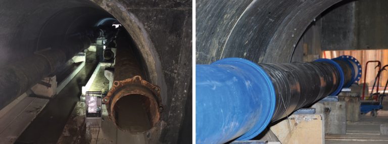
(left) Existing pipework within culvert with false floor installation being prepared for running of “dolly” system and (right) 450mm diameter ductile iron main within the culvert on existing plinths with new, purpose made support blocks – Courtesy of South East Water
Project challenges and engineering solutions – installing the temporary over-rider
Before Highways England was engaged, a solution was required to solve complex elevation and alignment changes the over-rider needed to tackle. Polyethylene ‘slingle’ bends, a new innovative pipework solution, was proposed to be installed at the top of the embankments either side of the Ford Lane bridge. This enabled the PE pipework to be orientated towards the connection point whilst simultaneously traversing down an embankment, all the while keeping the same internal bore. This was critical as any head loss would have had a detrimental effect on the supply to SEW’s Beech Reservoir.
Of all the challenges faced during the design phase of the project, gaining approval from Highways England was the most difficult and time consuming task. Both the SEW delivery team and its framework contractor Clancy Docwra Ltd, had to work in collaboration with Highways England to ensure the solution would be both safe and not disrupt motorway traffic.
As the over-rider would be placed on the bridge deck of one of their assets (Ford Lane bridge), the delivery team needed to prove the added weight wouldn’t compromise the structural integrity of the bridge, especially as the M20 was directly below. The total combined weight of the pipework on the bridge (including all the associated traffic management required) came to just over 330kg/m, where the maximum loading limit was stated as 500kg/m.
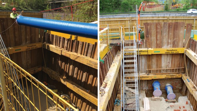
(left) Lowering of 450mm diameter ductile pipework into northern access shaft and (right) north access shaft and reinstatement of brick culvert window upon completion of installation of new mains through culvert – Courtesy South East Water
Highways England’s main concern however was the contingency plan for dealing with water if the over-rider was to burst. In order to satisfy their safety requirements, the project team proposed the main should be protected by a steelwork safety barrier system (Varioguard), which would be anchored just outside the proximity of the bridge deck at both ends. This, combined with a reduced speed limit and a two-way traffic light system, would adequately protect the over-rider from any vehicle strike.
If there was to be a leak, the team also proposed the pipework be installed within a 600mm twin-wall ridgi-duct, thus any water escaping during a burst/leak scenario, would be carried safely away from the motorway.
Project challenges and engineering solutions – mains replacement
The choice of the pipework material for mains replacement down the embankment and through the tunnel needed careful consideration so as to maximise the design life of the new mains.
Both polyethylene and DI solutions were explored. This gave the team two potential options, two 500mm OD PE100 SDR13.6 mains or two 450mm anchored DI mains. In the end it was found that a combination of the two was required.
The main advantage of using PE through the tunnel would be a faster installation method, as the pipework could be butt-fused outside of the tunnel and then pulled through. In total, it would have reduced the programme by four weeks compared to using a DI solution. However, as the pipework would be unsupported, pipework would expand and contract over a longer period, thus creating enormous pressures and ultimately causing the pipework to fracture/fail. Furthermore, the entire pipeline would need to be changed to barrier pipework to overcome potential hydrocarbon contamination. For these reasons, a DI solution was utilised.
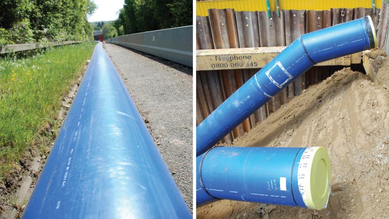
(left) View of 450mm PE over-rider pipework heading towards southern side of site and (right) twin 500mm OD PE100 SDR13.6 pipes from northern access shaft leading to connection onto existing mains – Courtesy of South East Water
Although through the tunnel any expansion and contraction of the PE pipe could cause failure, on the embankment the pipework would be supported effectively. This is where one of PE’s unique properties can be utilised. As the pipework was to be butt-fused together into one continuous length of pipe, this would negate the need for any thrust restraint compared to a DI solution. This was an advantage in this scenario due to the poor ground conditions and high test pressures, and was ultimately what swung in PE’s favour for the embankment works.
Whilst it was decided that a DI solution would be used through the tunnel, there was still the issue of how to solve the water ingress problem into the tunnel. During the early stages of design, both a structural and existing pipework survey was carried out within the tunnel itself.
Although the tunnel was structurally sound the existing pipework’s design life was coming to an end. This was due to water ingress seeping through the cover slabs above and eroding the coating of the existing pipework.
In order to overcome this and secure the 80 year design life of the new pipeline, the pipework was tape wrapped and the shafts at either end sealed shut with large diameter covers.
Construction
One of the biggest risks during construction was working within both the tunnel and the deep shaft excavations to reach it. As both were categorised as an NC3 medium risk confined space, in order to declassify the space to a low risk, a forced ventilation system was utilised during entry. Reducing the confined space to a lower risk enabled hot works to take place within the tunnel. This allowed for the existing pipework to be cut and extracted in manageable sections. This saved both time and money whilst creating a safer working environment.
Extraction of the old pipework required Clancy Docwra to create a ‘railway track’ in between the concrete supports, and cut-back the existing western plinths to create a greater working area. This way the old pipework could be rolled onto a ‘dolly’ system, transported out of the tunnel and finally lifted out of the excavation.
For the removal of the 400mm DI pipeline however, a pipe jacking table was used to lift the pipe into the centre and finally rolled onto the ‘dolley’ to be extracted. By carrying out this work sequence, lifting was minimised to simply jacking up the pipework thus creating a safer working environment. The maximum lift undertaken was 75mm in height.
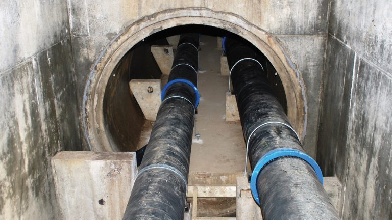
2 (No.) 450mm pipes installed within the existing culvert – Courtesy of South East Water
Testing the pipework for the scheme was particularly challenging due to the high test pressures (17 bar test pressure) and the different types of pipework used throughout the scheme. In particular, the testing through the tunnel had to be completed as a stand-alone test, with no direction changes and with straight pipe only. With these design statements in place, the new pipework through the tunnel could be tested safely.
Furthermore, as the new pipework was anchored, the hydrostatic pressures created during pressure testing had an equal and opposite reaction all the way through the pipe system. This allowed for the testing to be completed without the need for a bracing system at either end of the pipe. This was great news considering the thrust force created at that test pressure was in excess of 600kN (300kN per pipe run).
One of the other drivers for replacing the pipework through the tunnel was that the existing timber pipework supports had completely rotted away in most places. This meant the pipework was unsupported thus creating a concertina effect. In order to combat this in the future, the new pipework was placed on bespoke polyethylene support blocks.
The existing straps were also removed and replaced by new mild steel straps which were then anchored to the floor of the tunnel rather than the concrete support plinths.
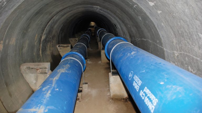
New 450mm ductile iron mains with new mild steel straps – Courtesy of South East Water
Environmental considerations
This scheme faced a wide range of environmental constraints and challenges, including dealing with protected species such as great crested newts, managing Japanese knotweed and dealing with contaminated land and protected trees.
Progress north of the M20 which was constrained by not only the movement of great crested newts but the presence of a number of protected trees, was achieved with minimal environmental disruption by using appropriate programme timing and construction methods. The main works were undertaken during the winter months thus reducing the risk of encountering any great crested newts and other dormant species.
Progress south of the M20 was affected by the invasive Japanese knotweed as well as contaminated land (including asbestos).
Summary
The scheme was completed in July 2017 and is considered a success, as the new pipeline was in commission before the summer demand period, and having been delivered within the cost and performance standards despite the significant challenges faced during the course of the project.
This potentially dangerous part of the network has been made safe and the public can be confident of a safe and secure supply of potable water.


