
Woolston WwT Scheme – Part 4 (2019)
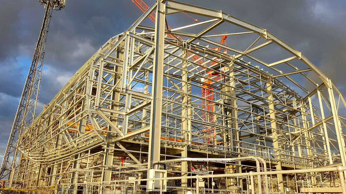
Primary building steelwork - Courtesy of Southern Water
Woolston WwTW uses a conventional activated sludge plant (ASP), built in 1966, treating sewage flows from part of the Southampton conurbation, serving a population of approximately 62,000 people. The site occupies an area of 1.26 hectares. The existing sewerage system which feeds into the WwTW collects both wastewater and stormwater from the Woolston catchment area. At present wastewater is continuously treated and the treated sewage effluent is discharged into the River Itchen Estuary through the final effluent outfall. Existing storm and final effluent discharge points will remain unchanged during the works.
This is the fifth paper in a series of case studies detailing the scheme and follows on from the fourth year of the Woolston WwT Scheme (2018) and previous years’ articles published in UK Water Projects.
Undertakings
4Delivery, a joint venture between Veolia Water Technologies, Costain and Stantec UK, is undertaking the design and construction of the project on behalf of Southern Water.
The permanent works treatment process will fully treat flows up to 36.9 MLD, in compliance with the new discharge permit requirements. All future permanent processes will remain within the boundary of the existing site.
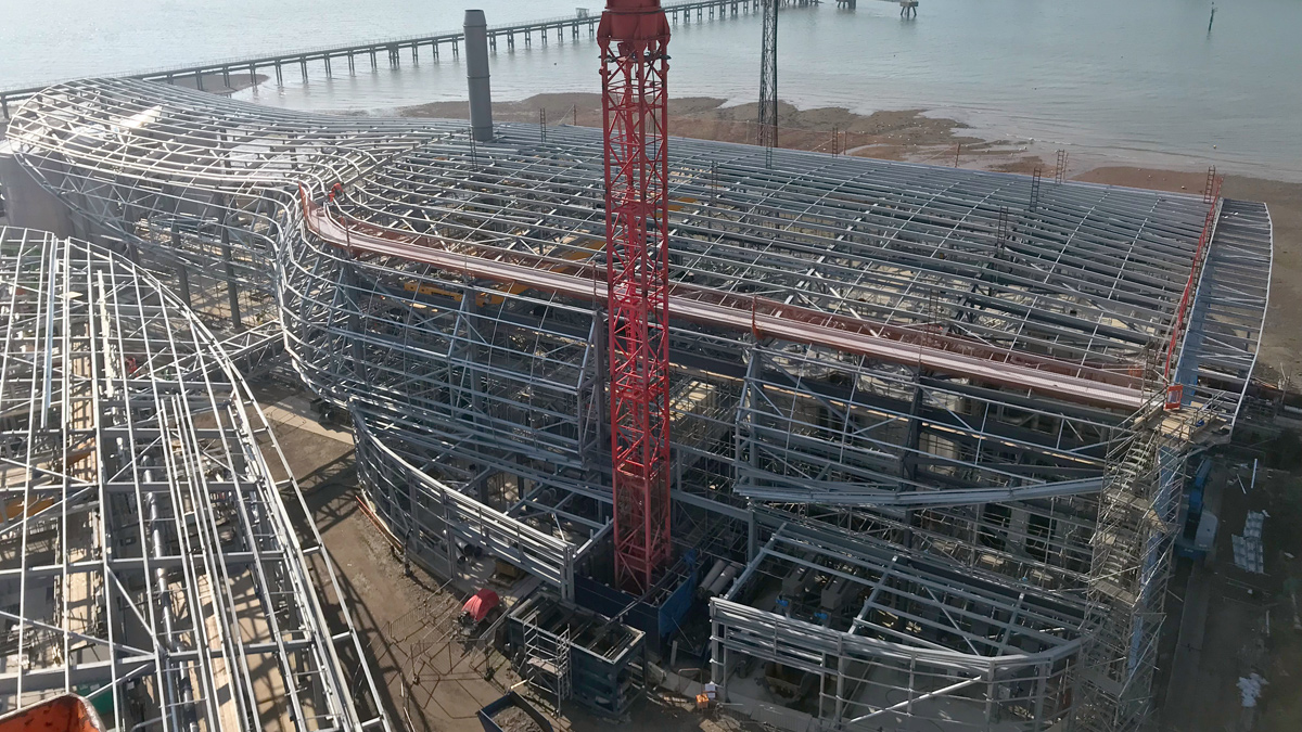
Overview of primary building – Courtesy of Southern Water
Existing site
The existing wastewater treatment includes:
- Inlet works comprising:
- Coarse and fine screens and screenings processing.
- Fat, Oil, Grease and Grit, (FOGG) removal and processing.
- High rate primary sedimentation lamella process.
- Membrane Bioreactor (MBR) plant comprising:
- Modified Ludzack Ettinger (MLE) activated sludge plant (ASP) for the biological removal of nitrogen.
- Membrane filtration tank, utilising microfiltration hollow fiber membranes.
- Existing ASP converted into a storm tank.
- Odour control comprising of chemical scrubbing and carbon units.
The sludge recycling includes:
- Sludge storage and blending.
- Indigenous sludge dewatering and processing.
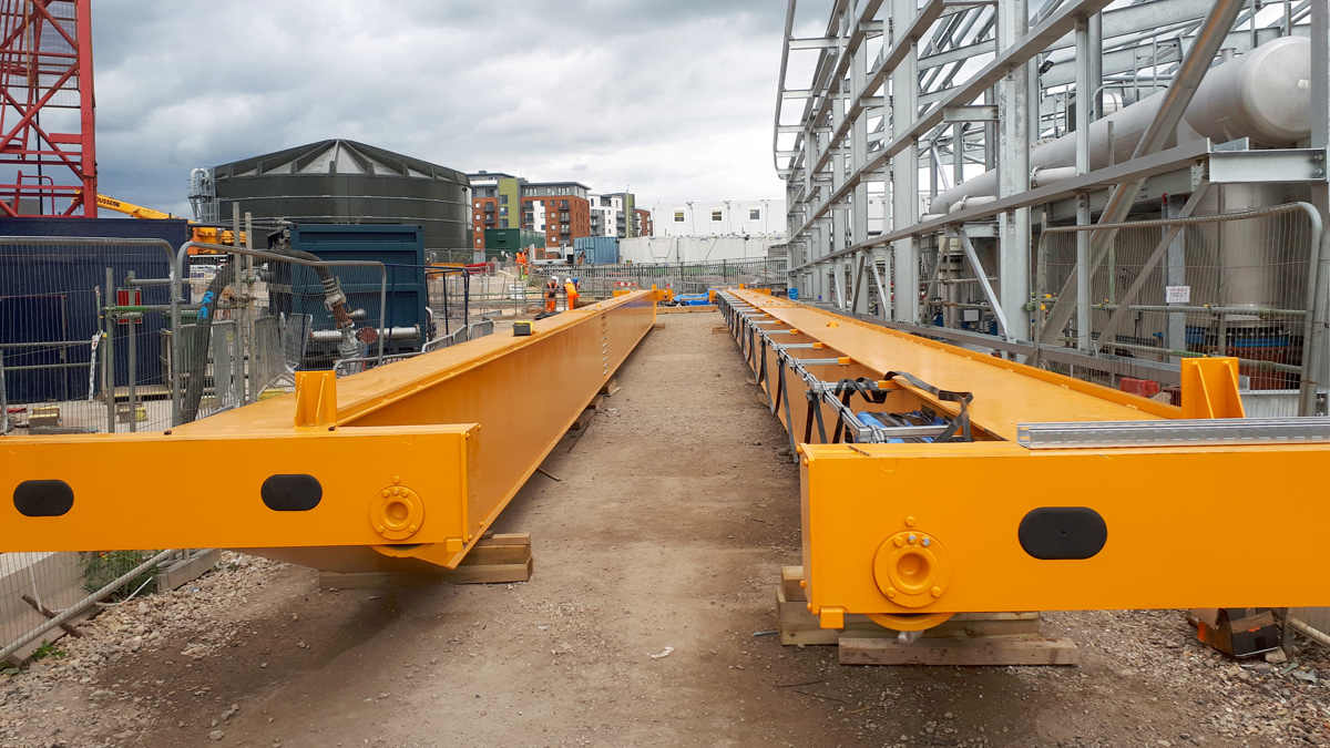
Building gantry crane – Courtesy of Southern Water
Improvement drivers
The Woolston works discharges into the River Itchen Estuary within the Solent and Southampton water Special Protection Area (SPA), which has been designated as a nitrate-sensitive zone by the Environment Agency. Southern Water is required to provide nitrogen removal for the Woolston catchment to comply with the European Urban Wastewater Treatment Directive (91/271/EEC) and associated Urban Waste Water Treatment (England and Wales) Regulations 1994 as well as nitrogen removal requirements under the habitats directive. A new effluent discharge permit requirement of ≤15 mg/l total nitrogen (TN) has been imposed as part of a coordinated strategy involving changes at other wastewater treatment works.
Dispersion modelling predicts that the impact, due to odour from the existing wastewater treatment works at Woolston, is substantial and extensive. Once the installation is completed, with a stack on the primary building for the central odour control facility, all ground level impact remains below the target value of 1.5 ouE/m3 at all locations.
Enabling works
The Woolston WwTW site is small in size and has a congested layout creating a challenging area in which to construct three large building structures. In order to provide significant programme savings 4Delivery, and Southern Water have leased an area of land from a neighbouring development owned by the Homes and Community Agency (HCA).
The enabling works have been constructed and were commissioned in December 2015. These process units provide primary treatment of wastewater, stormwater storage and sludge storage to allow Southern Water to continue to meet their environmental permits whilst construction within the extents of the Woolston WwTW site are completed. Secondary treatment (ASP) within the existing Woolston WwTW site is used to complete the treatment of wastewater whilst the new primary and secondary treatment processes are constructed. Demolition of the existing process units took place in early 2016. Once the permanent process streams are commissioned, the enabling works primary settlement tanks (PSTs) will be utilised as part of the secondary treatment to allow the existing final settlement tanks (FSTs) to be demolished. This creates the opportunity of constructing the new Sludge facilities ahead of the programme providing an additional saving to the client.
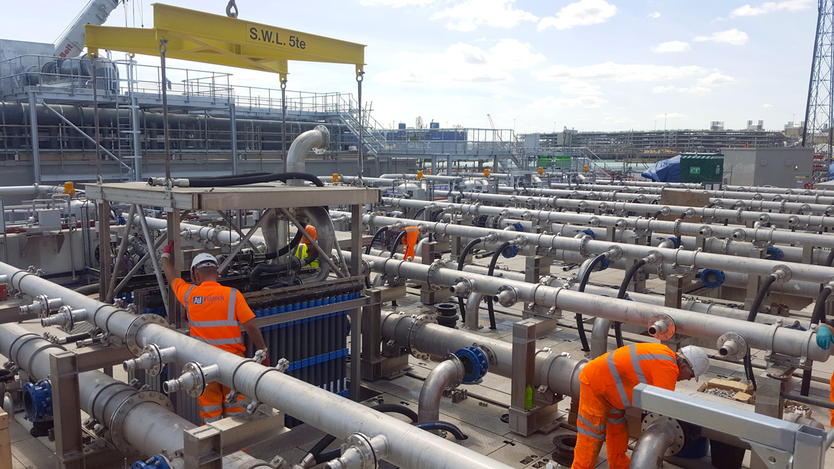
MBR lanes – Courtesy of Southern Water
Membrane bio reactor (MBR)
An MBR (membrane bio-reactor) has been installed at Woolston capable of treating FFT (flow to full treatment) flows up to 427 l/s. The MBR technology used is a hollow fibre type, supplied by Koch Membranes who were selected following a competitive tender. The membranes have a nominal pore size of 0.03 microns and are therefore considered to be in the range of ‘ultrafiltration’. Whilst not required by the Woolston consent, the installed membranes also meet the Environment Agency (EA) treatment disinfection standard.
The use of membranes as a separation barrier results in secondary treatment being closed loop in nature for solids or other debris. For this reason, enhanced pre-treatment is required in order to protect the membranes from debris, abrasives and fats. At Woolston this has resulted in the application of two-stage inlet screening (25 mm 1D coarse screening followed by 6 mm 2D fine screening), FOGG (Fats oils grease and grit) tanks, lamella settlement tanks and 1.5 mm ultra-fine screens (without a bypass) prior to the secondary treatment.
MBR module – Courtesy of Southern Water
For an MBR works, Woolston is relatively unusual, the Modified Ludzack Ettinger (MLE) process is configured as a ‘pump from system’ configuration. This means that membrane recirculation pumping occurs after the membrane tanks, as opposed to before it, which is a more conventional ‘pump to’ configuration. The pump from configuration, makes the MBR the lowest area of the secondary treatment and allows an overhead gantry crane, essential for removal for inspection and maintenance to be installed within the planning constraints.
The installed MBR consists of 8 (No.) trains with each train comprising 5 (No.) modules. Combined, this totals 62,640m2 of MBR surface area. Unfiltered flows weir from the MBR tanks to a RAS (return activated sludge) pumping station and are returned upstream of the aeration tanks. The MBR operates on a 4:1 flow ratio, whereby 4/5 of the flow is passed to the RAS pumping station for recirculation and 1/5 is filtered through the membranes. Including for works generated flow,s this leads to the RAS pumping at Woolston being rated for returns up to 2000 l/s, which is performed by 3 (No.) 1000 l/s duty/assist/standby RAS pumps.
A second recirculation loop is provided by a dedicated recirculation pump for each aeration tank to return flows to the anoxic zone to achieve the process/denitrification requirements.
Filtered flows, known as permeate are drawn (sucked) through the Pulsion LE-44 Koch Membranes by independent permeate pumps. Suction pressures across the membrane are dependent on the conditions but range from 0.05 bar up to their rated limit of 0.6 bar (~6 m water head).
Permeate flows combine in a manifold before entering a permeate tank. The permeate tank has a high-level weir overflow to ensure a sufficient volume is retained to fulfil membrane backwashing requirements. Finally, the flows pass to a final effluent monitoring chamber and washwater sump before leaving the site through an outfall to the River Itchen.
To maintain the process sludge balance, SAS (surplus activated sludge) is wasted from downstream of the MBR to a dedicated SAS pumping station. The take-off is designed to simultaneously capture and remove scum from the closed loop. SAS is passed to sludge holding tanks where it is combined with primary sludges before centrifuge thickening to 20-25% cake, ready for transport from site to a local sludge treatment centre.
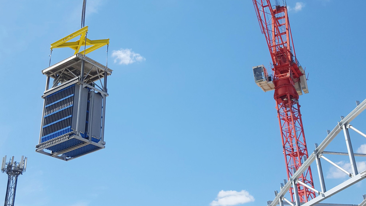
MBR module installation – Courtesy of Southern Water
Module installation
The modules were delivered to site om a just-in-time approach. They were lifted from the truck by a site crane to an assembly area. Here, extensive protective packaging was removed before mating the modules to their traverse frame and installing interconnecting pipework in order to achieve a standardised membrane module, complete and ready for inspection and sign off before installation into the prepared MBR tanks. Once in place, each traverse frame was levelled to ensure equal air distribution to each module to meet the cleaning requirements.
The final step before turning of flows was to perform a membrane leak test to ensure module integrity and sound piping connections.
Turn of flows
With the modules installed and integrity confirmed, flows were diverted to the MBR tanks in place of the two temporary FSTs and beneficial use of the MBR was achieved. For a few weeks following the turn of flows the plant continued to operate in a carbonaceous mode and the sludge settleability was poor (measured through a time to filter (TTF) test).
With confidence in the modules and control system the plant was seeded with sludge imported from local Southern Water sites and mixed liquors were increased over the following weeks to operational levels around 7000 mg/l. The process was optimised to stabilise the biological treatment, reduce TTF sludge filterability and reduce the transmembrane pressure required to filter.
SAT testing, commissioning & optimisation
Once installed and operational the control system functionality was fully checked for all required control. Finally, the control system was optimised for reliability and energy efficiency.
Enabling works demolition
Following the successful turn of flows through the MBR, demolition of the enabling works could commence. The enabling works as described above was built on leased land owned by the HCA.
The demolition allowed for a phased land handover to suit both the HCA and 4D requirements. Table 1 (below) describes the elements of the permanent design which were required to be operational before elements of the enabling works were able to be demolished.
Permanent works process equipment required to be operational
- ASP/MBR
- Flow to works pipeline and CSO chamber
- Sludge tanks and sludge treatment
- Site completion (staffing)
Element of enabling works released to be demolished
- 2 (No.) PSTs/storm tank/grit handling plant
- FFT pumping station
- Sludge tank
- Site cabins and MCC 1A (feeds site cabins & enabling works)
Sludge area construction
The sludge area construction consisted of:
- 2 (No.) 9.4m diameter 13m high, sludge holding tanks complete with mixers and access stairs.
- 2 (No.) centrifuges with associated feed and cake pumps. The cake pumps are rated for 25 bar pumping, assisted by polymer boundary layer lubrication in order to reduce pumping friction head.
- 4 (No.) sealed cake containers with weighing scales. The sealed cake storage allows for a period of no tanker movements during a long weekend.
- Dry and wet poly make up equipment.
- MCC & SCADA room.
- Site welfare including offices.
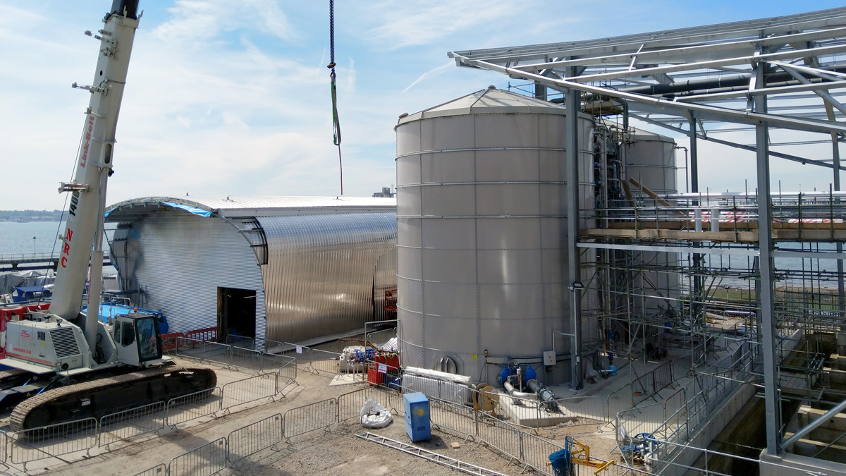
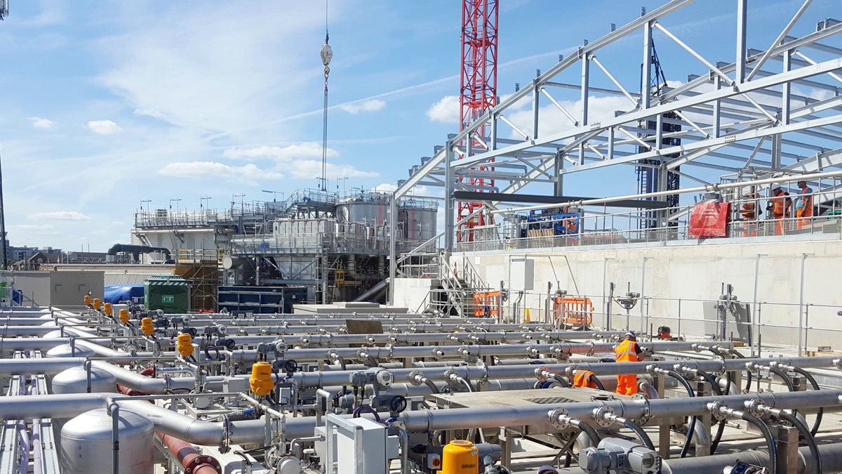
Sludge treatment area – Courtesy of Southern Water
Steelwork and cladding erection
The structural steelwork for the three building enclosures; primary treatment, secondary treatment & sludge treatment are now fully erected on site and the cladding is being installed on multiple workfaces. The current status of the cladding installation is approaching 50% complete as of July 2019.
As the process equipment was required to be constructed and commissioned prior to installing the steelwork. This presented a significant challenge to the steel erection team having to work above live process units. In order to overcome this challenge spider cranes were utilised as they were able to manoeuvre between the process units within the respective buildings. A high-level safety netting was also installed to eliminate the risk of falling objects.
The complex geometry of the buildings has also presented a challenge for the cladding manufacturers in terms of achieving the required curvature on some facets of the buildings. However, this is being tackled through use of the Bemo-Monro® system which uses the 3D model geometry as an input for precision-controlled fabrication equipment to create the required curvature on the standing-seam panels.
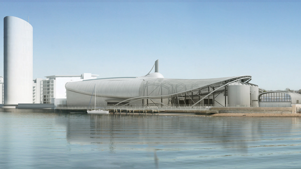
Woolston WwTW visualisation – Courtesy of Southern Water
Integrated services
Use of the fully federated 3D model was key to ensuring the building design did not occur in isolation. This enabled the design team to manage and avoid clashes and identify areas where the building structure could be utilised for support of plant and equipment.
For example, the odour removal and ventilation ductwork was designed to be supported by the building frames. One of the more complex areas of this was where the ducting from the secondary building was to run into the primary building at high level in order to feed into the odour control plant. This was achieved by providing a steelwork pipe bridge between the two buildings.
When the pipe bridge arrived on site ready to be installed it was fully assembled with piping, ductwork and services at ground level before being lifted into position. This minimised the requirement to be working at height therefore improving the safety of installation.
Another challenge was to integrate the building gantry cranes with the structural steelwork, because the cranes were 32m this exceeded the allowable transportable length. The cranes therefore had to spliced approximately in half for delivery then welded and bolted on site again at low level before being lifted into position.
Programme of work
- June 2014: Planning permission granted, followed by a six-week standard review period
- September & October 2014: Mobilisation of welfare units and project offices and construction of temporary treatment works begins on land adjacent to Woolston WwTW
- Late 2014: Earthworks and piling complete for the temporary treatment works
- Mid 2015: Temporary works complete, allowing the wastewater to be diverted from the existing site
- September 2015: Demolition of the existing site begins along with the construction of new site
- Summer 2019: Project take-over
- Autumn 2019: Work complete