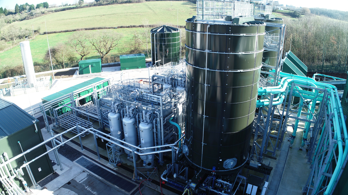
Cog Moors Advanced Anaerobic Digestion Facility (2021)
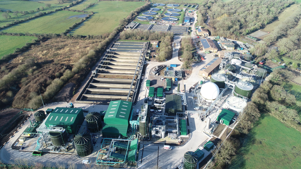
Cog Moors WwTW - Courtesy Welsh Water and Skanska
Welsh Water’s sludge strategy is to treat 97% of sludge using advanced anaerobic digestion (AAD) technology. The Cog Moors AAD facility was constructed to supplement the existing facilities at Cardiff and Afan in South Wales along with the recently constructed Five Fords facility in North Wales. AAD gives the benefits of:
- Meeting the Enhanced Sludge Standard under the Biosolids Assurance Scheme (BAS).
- Providing additional biogas generation and therefore additional electrical energy generation when compared with conventional anaerobic digestion.
- Reducing the digested sludge management costs, particularly transport costs, due to improved solids destruction and sludge dewaterability.
Cog Moors AAD
The AAD facility at Cog Moors utilises a thermal hydrolysis process pre-digestion and it will be capable of treating a design throughput of up to 20,200 tonnes dry solids (DS) per annum. The stabilised and sanitised digested sludge meeting the BAS standard allows a wider use in agriculture. The biogas produced from the anaerobic digestion process is utilised to generate electricity by two combined heat and power (CHP) reciprocating engines. The exhaust heat from the CHPs is used in two composite steam boilers and the low temperature heat from the CHPs is used to pre-heat the sludge feed to the thermal hydrolysis plant (THP) in order to optimise the process thermal efficiency.
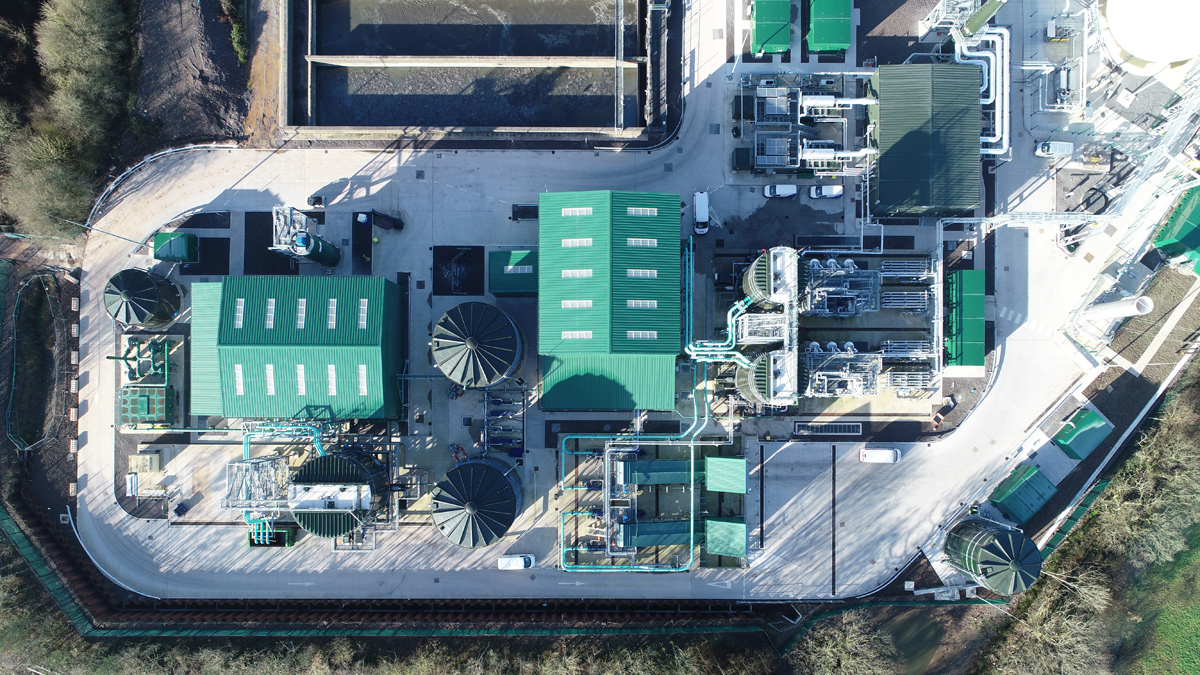
Boiler house, THP, sludge import and dewatering buildings – Courtesy Welsh Water and Skanska
The Cog Moors AAD facility is a regional sludge centre treating indigenous sludge, a combination of primary settled and surplus activated sludge (SAS), and imported sludge produced at satellite sites. As a proportion, around two-thirds of the sludge to be treated at Cog Moors AAD is imported sludge.
Cog Moors Advanced Anaerobic Digestion Facility: Supply chain – key participants
- Client: Welsh Water
- Principal contractor: Skanska
- Lead designer: Arcadis
- Boiler house: Dunphy Combustion
- Combined heat & power units: Edina
- Thermal hydrolysis plant: Cambi
- Siloxane removal plant: Pptek (Parker)
- Imported sludge reception & sludge silos: CTM Systems Ltd
- Centrifuges: Alfa Laval
- Polymer handling, make-up & dosing systems: Richard Alan Engineering
- Gas holder: AJ Tensile
- Flow controls: AUMA Actuators Ltd
- Flow controls: AFFCO Flow Control (UK) Ltd
- Digesters, sludge cake silos, process tanks: Stortec Engineering Ltd
- UV disinfection system: Trojan Technologies
- FE filters: Bollfilter UK Ltd
- Civil sub-contractor: Matcon
- Civil sub-contractor: CSF
- Mechanical installation, supply & design: Industrial Pipework Services (IPS)
- Electrical installation: Celtic Process Control Ltd
- Electrical installation: PCS
- Software/integration & MCCs: GPS Group
- Odour control systems: OSIL
- HV: SSE Contracting
Indigenous and imported sludges
The indigenous sludge is received from the Cog Moors STW into a combination of existing storage tanks and newly installed tanks. There are separate storage tanks for the primary settled sludge and SAS. There is separate tank capacity to allow the blending of sludge plus pre-THP centrifuge feed tanks. The total sludge tank storage volume capacity provides the equivalent of 2 days storage at the design throughput of indigenous sludge.
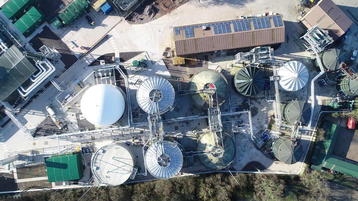
Anaerobic digesters, gas holder and post digestion sludge holding tank – Courtesy Welsh Water and Skanska
The primary settled and SAS is separately screened using duty/standby Strainpresses®. All the tanks are equipped with pumped mixing systems. The odorous air from all the storage tanks is extracted to one of three odour control units. The odour control approach across the facility is based upon first stage bio-scrubbing followed by second stage activated carbon before the treated air is discharged to the atmosphere.
The indigenous sludge is fed to four decanter centrifuges (two new machines and 2 refurbished) to dewater the sludge to 20-22% DS. A new powder polymer make-up plant (at 0.3-0.5% w/v) and dosing system to each centrifuge has been installed in a new pre-THP sludge dewatering building. The dewatered cake from the operational centrifuges is pumped into 2 (No.) 400m3 THP feed silos. The centrifuges and THP feed silos are also included in the odour control management.
Imported sludge is received into one of two enclosed reception units with accessible roller shutter doors which operate on duty/duty configuration. Odorous air is extracted from the units and treated in odour control units.
Each unit consists of a belt conveyor that transports the imported sludge cake to two screw conveyors which feed two transfer pumps per stream that deliver the imported sludge into one of the two THP feed silos. Heated disinfected final effluent (FE) is used to dilute the imported sludge to around 20-22% DS as it is transferred to the silos for storage prior to feeding the two THP streams.
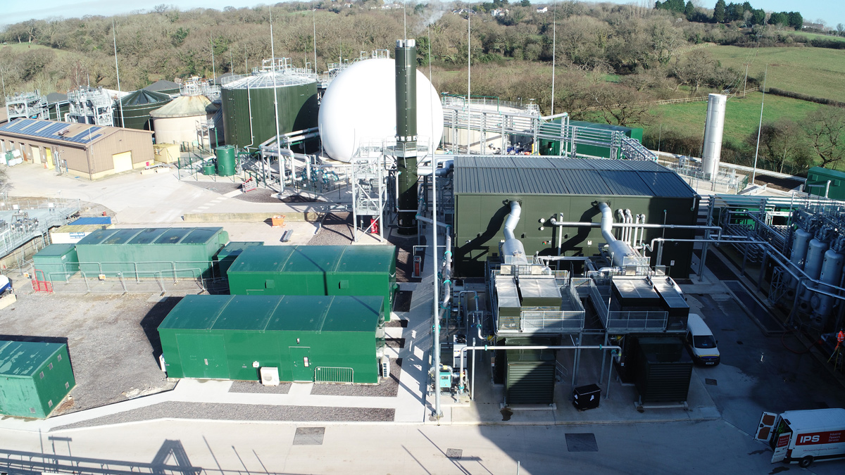
CHP gas engines integrated with the boiler house – Courtesy Welsh Water and Skanska
Thermal hydrolysis
There are two B4 Cambi® Thermal Hydrolysis Plant streams used to thermally hydrolyse the sludge prior to anaerobic digestion. The THP is used to solubilise sludge solid organics and to rupture biological cells allowing release of the cell contents. This process improves sludge digestibility, enhances the biogas yield and destroys pathogens. Each THP stream broadly consists of a pulper, three reactors, flash tank, process gas skid/cooler system and associated pumps between process stages. The imported and indigenous sludge leaving the THP feed silos is diluted using disinfected FE to around 16.5% DS and then pumped into the pulper stage of each of the THP streams.
The sludge in the pulper is pre-heated by receiving recycled steam from the reactors and the flash tank. Pre-heated sludge is pumped to one of three reactors, as requested by the control system, and steam is injected directly into the reactor, until the required operating pressure (6 bar g.) and temperature (165°C) is achieved.
The reactor cycles operate on batch philosophy. The reactor pressure is maintained for 30 minutes then a bottom valve on the working reactor is opened, and the sludge is blown down into the flash tank. This motive action is driven by the reactor steam pressure. The flash tank allows release of flash steam and provides buffer storage for the feeding of hydrolysed sludge, via sludge coolers, to the four mesophilic anaerobic digesters.
The thermally hydrolysed sludge leaving the flash tank is diluted using disinfected FE to allowing sludge feeding in the range of 8-12% DS depending upon the digester requirements. The THP is typically operating at a digester feed sludge concentration around 9%DS in order to manage the ammoniacal-nitrogen content to ensure stable operation of the digesters.
Pre-THP dewatered raw sludge silos and 2 (No.) THP process lines – Courtesy Welsh Water and Skanska
Anaerobic digesters
Two existing digester structures have been utilised and the sub-structure of two further digesters have been utilised with a new above ground superstructure constructed. The total digester sludge working capacity available is around 9,500m3. All the digesters are equipped with externally positioned pump mixing systems with appropriately positioned sludge draw off and returns in each digester to provide effective mixing.
Each digester is fitted with a sludge recirculation system transferring sludge to the THP to allow blending of the digesting sludge with thermally hydrolysed sludge before it enters a sludge cooler (heat exchanger) to cool the sludge mixture to ensure the digester operates at the around 37-39°C. Each digester has its own sludge recirculation and cooling system. Disinfected FE is used as the cooling fluid.
Biogas management and use
The biogas produced in the digesters flows from each digester via a foam trap and condensate pot to a 2000m3 double membrane gas holder. The biogas is principally utilised in the 2 (No.) CHPs (1.5 MW units) to produce electrical energy and the waste heat from these units is used to support the energy demands of the two steam boilers. The steam boilers are composite type with a waste heat section and dual fired burners able to use either biogas or natural gas as fuel. The energy source priority of the steam boilers is to initially use the waste heat from the CHP. The boilers produce steam at 10.5 bar g. to meet the demands of the THP and they operate on a lead/lag basis. There is also a waste gas burner to manage biogas in times of excess production and during maintenance.
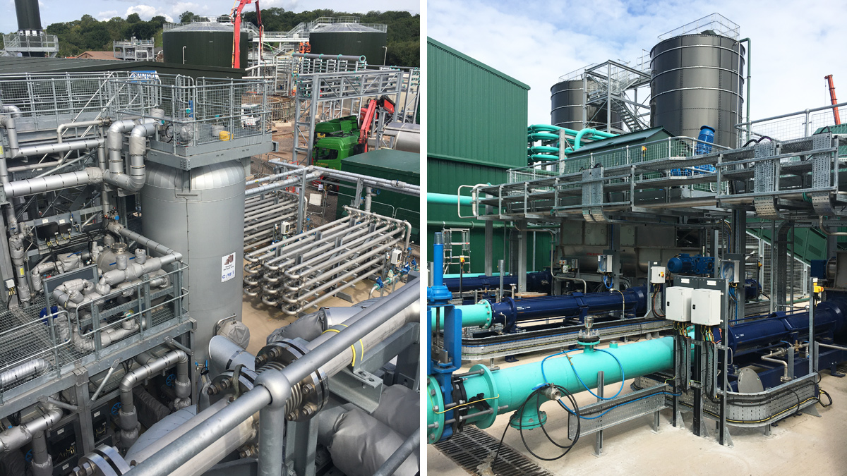
(left) Thermal hydrolysis plant and (right) imported sludge transfer system – Courtesy Welsh Water and Skanska
Digested sludge dewatering
The digested sludge leaves each of the four digesters via a high-level weir box and it flows by gravity to a twin compartment post digestion sludge holding tank (PDST) with total storage capacity of 1000m3. Each compartment of the tank is mixed using an air system to ensure consistent feed to the downstream centrifuges and to aid the removal of solubilised biogas to reduce the risk of forming explosive atmospheres. Digested sludge is pumped from the tank to three new decanter centrifuges that are designed to operate on a duty/assist/standby arrangement.
There is a new powder polymer silo, polymer make up system (at 0.3-0.5% w/v) and dosing pumps to each centrifuge. The system provides polymer solution to each operational centrifuge at around 0.15% w/v solution after dilution with carrier water. The dewatered digested sludge cake leaving the operational centrifuges is transferred by pumps into a storage silo (650m3). The silo is equipped with a sliding push floor to move the sludge to allow it to load a receiving sludge truck. The trucks transfer the digested sludge off-site for use in agriculture.
The centrate from the digested sludge has a high concentration of ammonia and organics. It is transferred with other wastewater streams from across the sludge facility back to main works for treatment via settlement and activated sludge treatment processes. The existing works has sufficient hydraulic and biological treatment capacity to cope with this additional load.
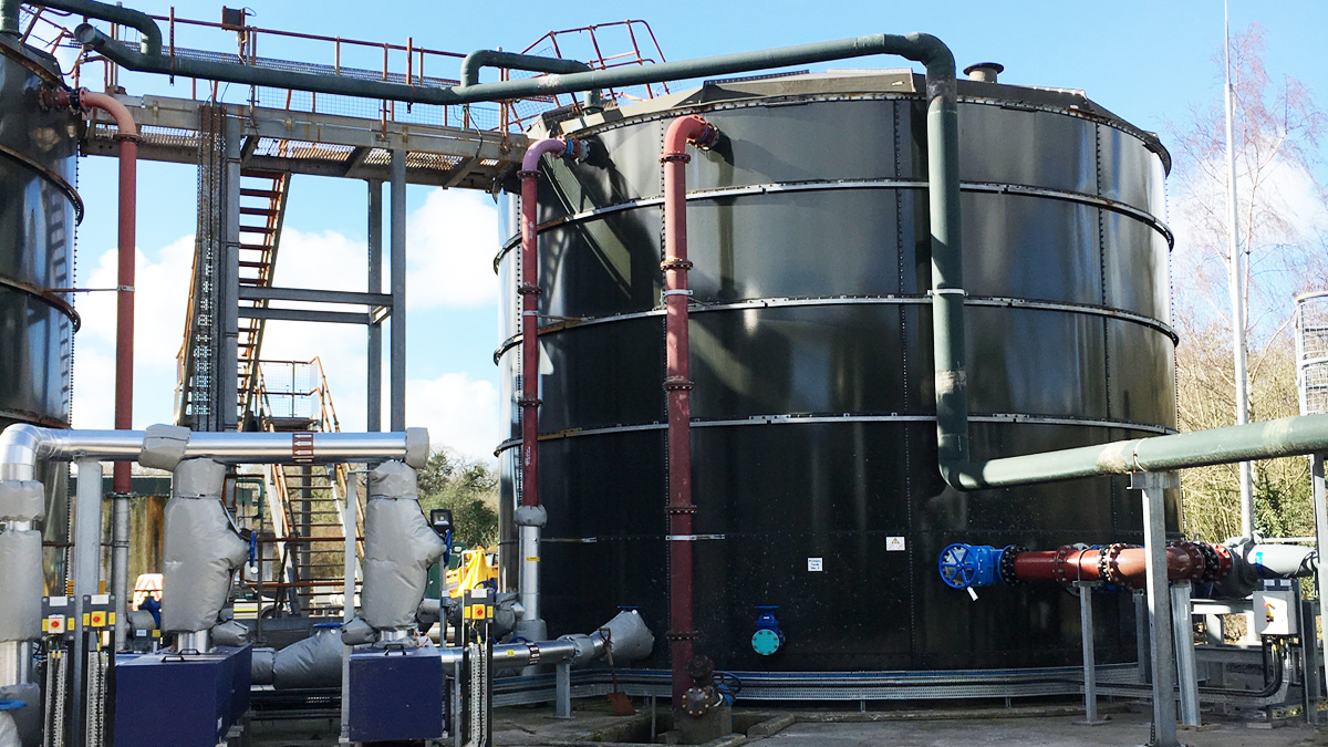
Re-used primary sludge storage tank – Courtesy Welsh Water and Skanska
Disinfecting final effluent
Water is required for several sludge dilution applications across the facility. The cheapest, sustainable, and most abundant option is to reuse FE. However, the use of FE in the sludge treatment process after the thermal hydrolysis process, is likely to result in a failure of the microbiological parameters, therefore a disinfection process is required to reduce the microbial content before using the FE. The FE leaving the final settlement tanks is pumped through two stages of boll type filters to prepare the effluent before being disinfected using two ultra-violet light disinfection units operating on a duty/standby basis.
Approach to commissioning
Two of four anaerobic digesters were initially part filled with disinfected FE (circa 300m3) and the digester contents were heated using steam from a hired temporary boiler. This initial digester heating was achieved by directly injecting steam into the digester contents. A temporary boiler was used due to the location of the digesters relative to the position of the boiler house.
The anaerobic digesters and all gas systems were purged using nitrogen. Dewatered digested sludge cake, from Afan AAD facility, was used to initially seed Cog Moors. The Afan seed sludge was micro-biologically compliant. The imported sludge reception units and transfer systems were used to handle the incoming seed sludge. Sodium bicarbonate powder was initially mixed with seed sludge to raise the alkalinity. The seed sludge cake mixed with sodium bicarbonate diluted with disinfected FE was pumped to one of the two THP feed silos. This seed sludge was diluted to around 8-10% DS and pumped via temporary pipework to the first digester to be filled. This was followed by filling the second digester with seed sludge.
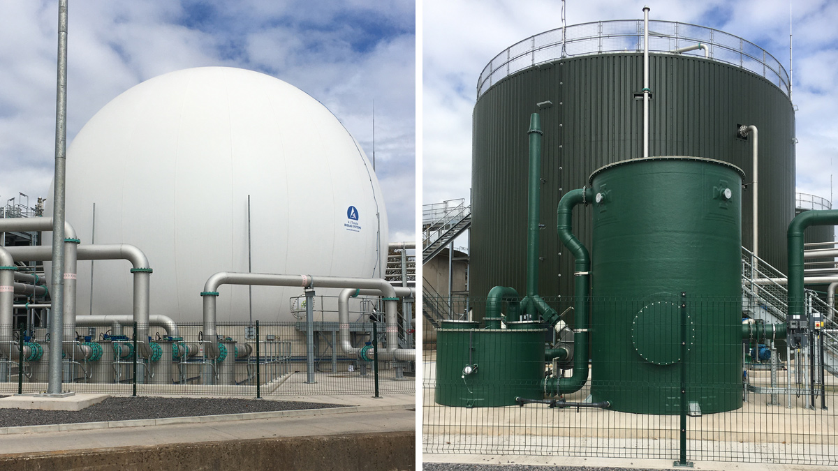
(left) Gas holder and (right) anaerobic digester in the background with odour control unit in the foreground – Courtesy Welsh Water and Skanska
Both digesters were filled to around two-thirds of their working capacity. The digesters continued to be heated gradually (circa daily rise of 1°C) using the temporary steam boiler. Once the seeding and heating was completed for the initial two digesters, the gradual feeding of the thermally hydrolysed sludge digesters began. The gradual digester feeding with hydrolysed sludge followed a daily increase of around 3-5% volatile solids to each digester. Once the initial two digesters were filled and they started to spill digested sludge from the weir box into the PDST.
Just prior to the first two digesters being filled, the other two digesters were then part filled with disinfected FE and purged with nitrogen. Then this second set of digesters were gradually pumped filled with digested sludge from the PDST. Once these digesters were about two-thirds filled with a mixture of disinfected FE and digested sludge then thermally hydrolysed sludge was fed on gradual basis to these digesters. Initially natural gas was used to fuel the boiler house steam boilers to provide steam to the THP.
This continued while the quality and quantity of the biogas being produced improved. The temporary steam boiler also continued to be used until the daily digester feeding was sufficient to maintain the digester temperature due to the heat losses to the environment.