
Ellesmere Port WwTW: Essar Upgrade (2022)
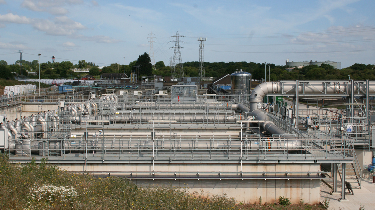
Ellesmere Port IFAS plant - Courtesy of United Utilities
The large industrial town of Ellesmere Port in Cheshire is experiencing population growth, thanks to good transport links and an array of employment opportunities. The local population is set to rise by a further 10% by 2036, to over 76,000, so upgrades to the Ellesmere Port Wastewater Treatment Works (WwTW) are necessary to cope with increased throughput. Essar Oil UK Ltd, which operates the Stanlow Oil Refinery in Ellesmere Port, will be significantly increasing the trade effluent flows and loads sent to Ellesmere Port WwTW for treatment by September 2022, and this is the primary driver for the project. In 2018, United Utilities and C2V+, a joint venture between VolkerStevin and Jacobs, began a £24m upgrade to the works to provide new secondary and tertiary treatment plant along with a sludge thickening system. A new pipeline from the Essar site to the balancing tanks within the WwTW is also part of the project.
The plan
Ellesmere Port WwTW receives crude wastewater into the inlet works from the surrounding catchment and from several traders. Currently, it receives a relatively small portion of its flow and load from Essar’s Stanlow Oil Refinery located on the opposite side of the main A5117 road from the WwTW. The oil refinery plans to significantly increase the flows and loads it sends to Ellesmere Port WwTW. As a result, the quality of the effluent discharged to the watercourse will need to be improved and a change to the existing discharge permit will be necessary.
The solution, which will be built at the WwTW, is intended to provide wastewater treatment for the additional biological load expected from Essar and to compensate for population growth. The new permit is ready and will be transferred to United Utilities now the additional flows from Essar have started to be delivered and the works are being commissioned.
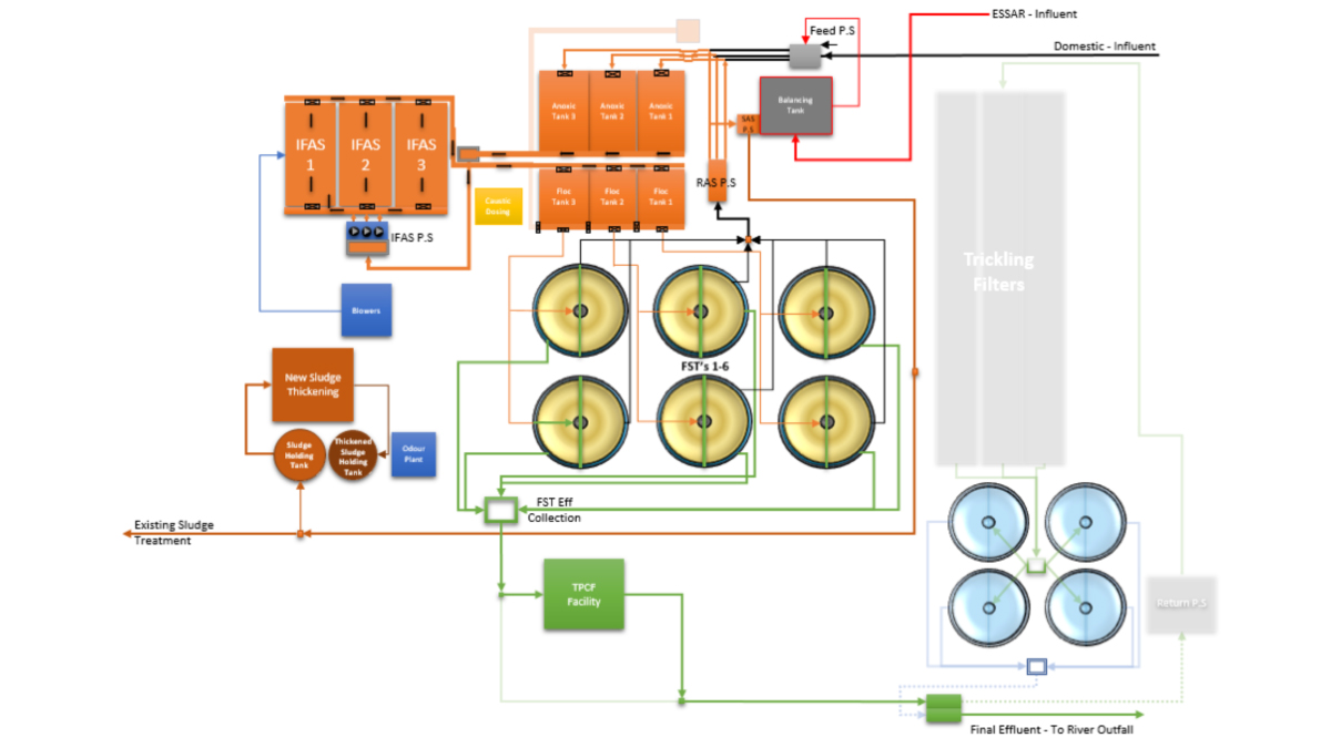
Flow diagram of new plant – Courtesy of C2V+
Chosen option
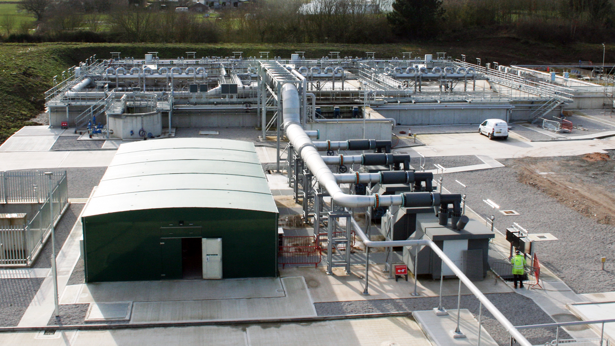
The chosen option was to install a new 11,100m3 integrated fixed-film activated sludge (IFAS) plant. This option was taken forward because the IFAS process uses suspended biofilm carriers to grow additional biomass. This greatly reduces the required bioreactor volume. The IFAS has three cells which gives it greater flexibility of media fill and this allowed the plant to accommodate the reduced load from Essar.
C2V+ was able to draw upon experience from the US market, due to parent company Jacobs.
This is the first time that a dispersed media IFAS plant has been integrated into an existing activated sludge process (ASP) in the UK. Whilst an ASP would provide adequate treatment, the IFAS process has a lower whole life cost due to its smaller footprint, which is hugely beneficial to the client and the wider industry.
Technical uncertainties
A major uncertainty is the impact on the IFAS process of the timing and volume of additional biological loads expected from Stanlow Oil Refinery. There is no precedent for similar plants encountering increased loads at these levels, therefore this project will improve metrics and knowledge for future projects.
IFAS Cell A in full operation – Courtesy of United Utilities
Incoming streams
This project is unusual because there are three separate incoming streams. To date, the design team were not aware of any municipal plant that has had three incoming streams with such unrelated chemical properties, as noted below:
- Catchment loads are dependent on storm events and winter/summer variants.
- Incoming imported sludge tankers: Timing is dependent on United Utilities’ daily demand and tanker fleet movements.
- Oil refinery influent: This is entirely out of the control of the treatment works and could peak at any time dependant on the refinery process discharge. However, design parameters were agreed upon at contract.
The design
The design has been completed using Jacobs PRO2D process modelling. In the IFAS process, the kinetic rates are critical for the nitrification process. In general, the reaction rate depends on the concentration of reactants. The dependence of reaction rate on concentrations of reactants can be expressed mathematically in terms of the reaction rate constant and the powers of concentrations of reactants. The adoption of this method is due to the lack of historical data and unknowns associated with the increased influent from the refinery.
The influent temperature to the bioreactor is a critical component of the design, yet will be unknown until final flows to the cells are received in 2022. Historical temperatures have been collated and modelled and assumptions made around future temperature profiles.
Once the full flows are integrated into the system, a one-month summer and one-month winter testing period will take place. Afterwards, all of the modelled parameters will be reviewed, and modifications made, thus ensuring the effluent from the plant meets the environmental permit.
The IFAS plant has been running on low flows from Essar for several months up to April 2022, since then Essar has started to increase load and flows on a monthly basis. Once the IFAS has settled with the new flow and load, then summer testing is expected to start in August 2022.
Installing final batch of media – Courtesy of United Utilities
Three IFAS reactors were installed with a total working volume of 11,100m3 and a working depth of 7.0m. The IFAS tank design was for a 34% fill of 800m2/m3 specific surface area moving bed IFAS media, media retention screens and coarse bubble aeration grids. However a media fill range of 25% to 65% is possible which allows for headroom. The original three-lane ASP was upgraded and re-configured to three anoxic cells upstream of the IFAS and three floc tanks downstream of the IFAS.
A detailed storyboard was developed by C2V+ to plan the phasing of the new works commissioning alongside existing operations and to ensure compliance with current permits.
Essar Pipeline
As part of the delivery package, the project had to design a new pipeline and route from where the existing Essar Pipeline originally entered the WwTW and then take the line, over ground, to the post primary settlement entry point into the WwTW at the refurbished balancing tanks.
A 400mm diameter glass reinforce epoxy (GRE) pipe was installed. The pipe length was 600m and this included three road crossings on pipe bridges, and a bridge support across a brook. The new pipeline was pressure tested in April 2022 ready to take the new flows from Essar. On Wednesday 11 May 2022 the new flows started to arrive from Essar.
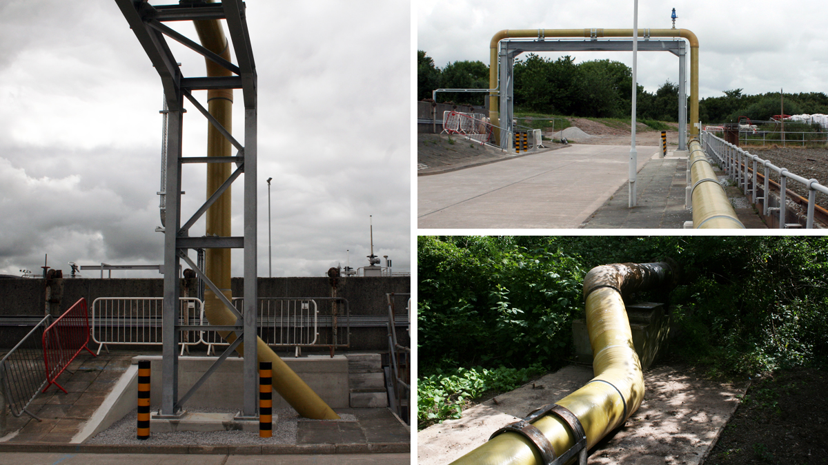
Pipe connection into Essar pipeline – Courtesy of United Utilities
Ellesmere Port WwTW: Essar Upgrade: Supply chain – key participants
- Main design & construction contractor: C2V+
- Designers: Jacobs
- Ground investigation, boreholes & soil sampling: Geotechnics Ltd
- IFAS system: ACWA Services
- Formwork, reinforcement & concrete works: E Flood Construction
- Mechanical installation, metalwork & flooring: JB Fabrications
- Electrical installation: Eric Wright Water
- System integration: Tata Consultancy Services
- Tertiary treatment cofferdam: VolkerGround Engineering
- MCC: Lloyd Morris Electrical Ltd
- MITA tertiary treatment plant: Evergreen Water Solutions Ltd
- RMU & MCC kiosk: Morgan Marine
- SCADA works: Ramptec
- Aeration blowers: Xylem Water Solutions UK
- IFAS metalwork & SW pump station: Franklyn Yates Engineering
- Sludge storage tanks: Balmoral Tanks
- Sludge thickening plant: Alfa Laval
- IFAS lift pumps: Bedford Pumps
- Penstocks & stop logs: Glenfield Invicta (AVK)
- Polymer dosing: Northern Pump Suppliers
- Office & welfare cabins: VolkerBrooks
- Bitumen surfacing: Huyton Asphalt
- Flow controls: Auma Actuators
Tertiary treatment plant
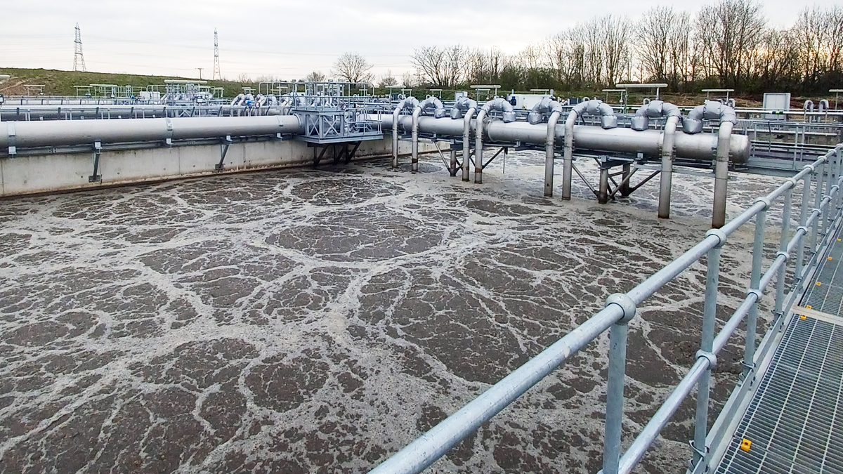
Tertiary treatment processes have been used for many years to polish effluent, reducing concentrations of suspended solids (TSS), biological oxygen demand (BOD) and ammonia in wastewater and effluent treatment plants. Tertiary cloth pile filters were installed to ensure the WwTW could meet the tight 95th%ile and upper tier BOD and permits. In addition, the tertiary filters will be used to protect against solids carry over in the event of a bulking incident caused by the trader influent.
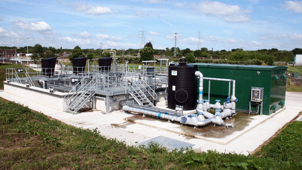
Tertiary plant looking north west- Courtesy of United Utilities
MITA cloth filtration system
The MITA Water Technologies pile cloth filtration system from Evergreen Water Solutions Ltd allows TSS removal in tertiary phases of wastewater treatment works. The filters can be used with or without upstream chemical dosing. The system provides solid separation using a deep pile cloth which combines the characteristics and advantages of surface filtration with that of deep bed filtration. The MITA cloth filter is made up of a series of filter discs mounted on an inner tube making it a very compact design. The central drum supports up to a maximum of 32 discs; each disc comprises six sectors made of reinforced plastic and each covered with an individual deep pile cloth. Some special features of the MITA cloth filters include:
- Externally mounted backwash pumps.
- Fully decked filter with small panels for safe maintenance.
- Variable speed drive motor.
- Double chain drive.
- Heavy duty backwash mode.
- PLC control.
Energy consumption (W/m3 of effluent treated) for the MITA filter is extremely low, which is a fundamental driver in process selection. Wastewater flows to each filter, though an inlet channel. The liquid level in the filter chamber is typically just above the cloth covered discs. The level is controlled by the outlet weir. The entire area over the filter is covered by open grid removable GRP decking. The influent (after secondary clarification) passes through the filter cloth whilst the solids are retained on the cloth pile fibres. Cloth filtration occurs under gravity flow, with all discs completely submerged.
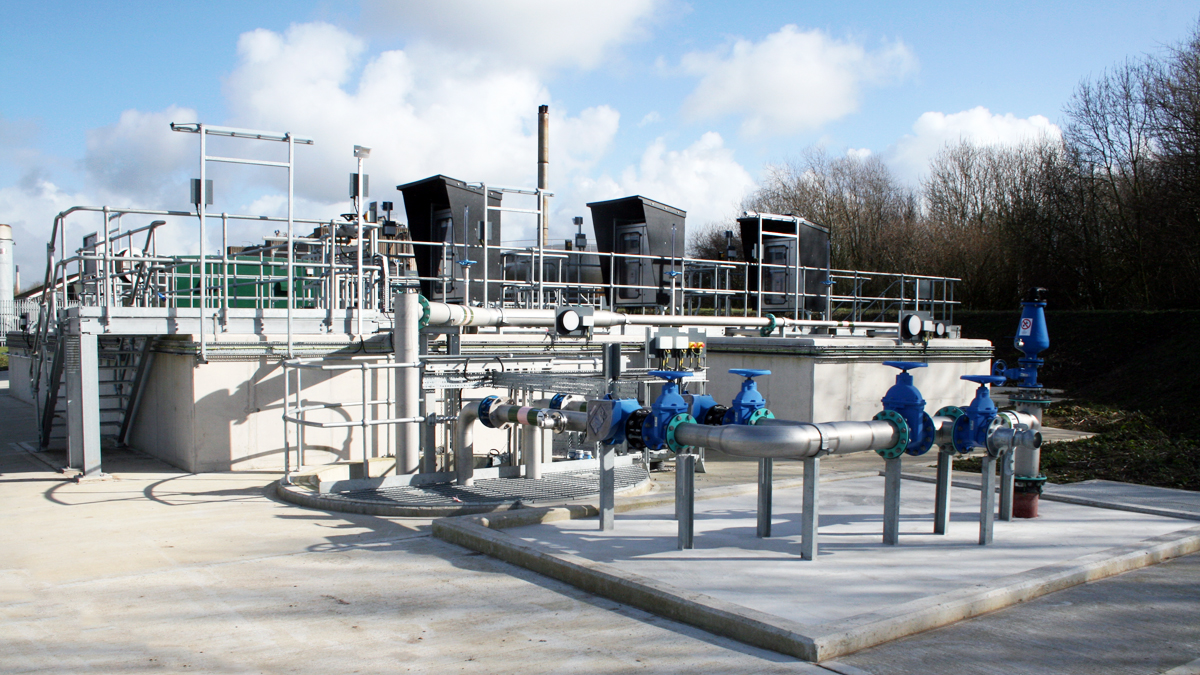
Tertiary treatment plant – Courtesy of United Utilities
The discs will be stationary unless the solids collected on the cloth has resulted in a head loss sufficient to generate a backwash cycle. As only a small percentage of the total filter area is cleaned at any instant, the remainder or the filter cloth can continue to filter the wastewater stream as normal.
The disc segments are covered with a removable cloth, which is a woven ‘pile’ fabric. During the filtration phase, the direction of flow causes the fibres to lie flat against the support panels. This results in a fine filtration matrix of overlapping piles. This creates layers for the separation and retention of suspended solids in a similar manner to sand filters. Each segment of the cloth filter disc has its own individual cloth membrane that can be replaced. The standard pile cloth (10 micron equivalent) was installed at Ellesmere Port.
The footprint of a deep pile cloth filter compared with that of a deep bed sand filter is significantly reduced.
The online backwashing of each filter means that all filters are permanently operating and the use of the filtered water from within the filter itself eliminates the need for a backwash water reservoir.
Ellesmere Port IFAS plant – Courtesy of United Utilities
Operation
During normal operation, solids are deposited on the cloth, causing the water level in the filter basin to rise, compared to the height of the exit weir. When a pre-set differential level is reached, the cloth backwash sequence is activated: a unique pumping system, connected to a series of suction nozzles, removes the solids retained on the cloths, resulting in lower operating head loss.
During the backwash process the fibres are raised inside the backwash nozzle, in such a manner that the solids, previously captured, can be readily removed by the counter-current water flow. The backwash water is supplied by the filtered water contained within the filter disc drum. The backwash water (including retained solids) are returned upstream to be co-settled. Solids settling in the bottom of the filter tank can be removed by a pump controlled by a timer.
The tertiary plant has been fully constructed and at the time of writing (August 2022) is undergoing full commissioning procedures. Some minor adjustments have been made to stop air getting into the pump manifolds. This was achieved by extending the baffle plates down to the bottom of the inlet pipes and stopping the problem of air entrapment.
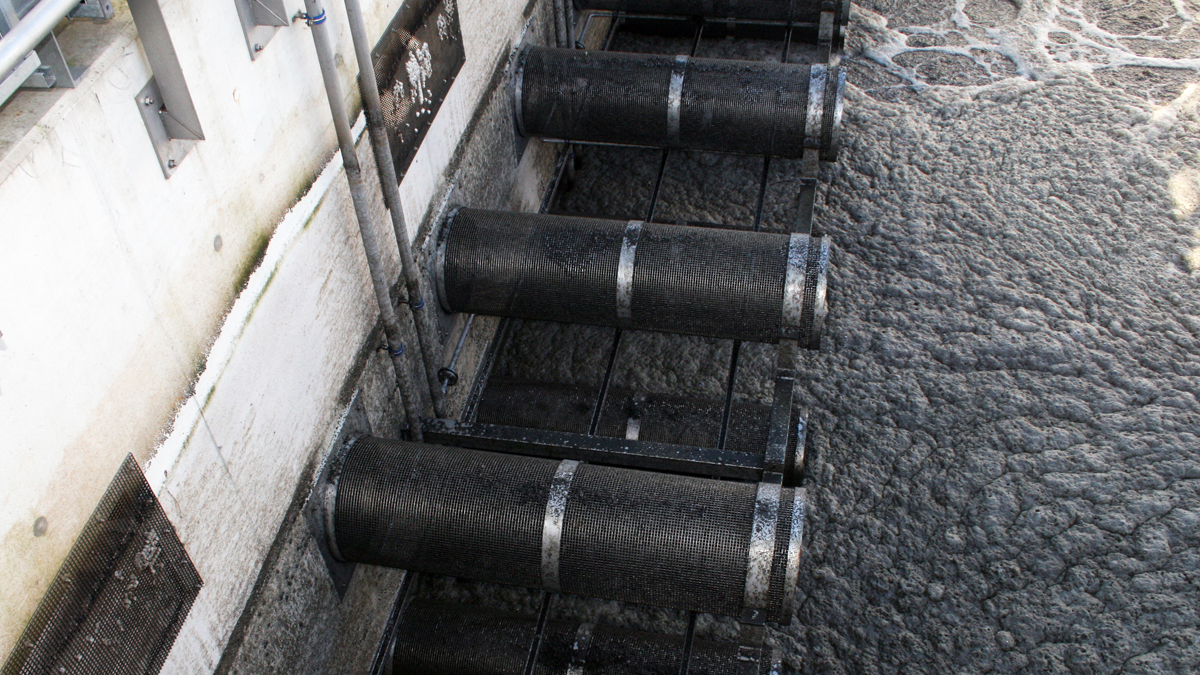
IFAS sieve arrangement – Courtesy of United Utilities
Project progress (as of August 2022)
Work on site began in May 2018. The new IFAS tank structure has been completed and various ancillary and associated infrastructure works are also complete.
The old aeration tanks were modified to create the anoxic zone and three parallel aeration cells A, B and C. The mechanical and electrical packages are complete and undergoing commissioning and integration with PLCs and SCADA.
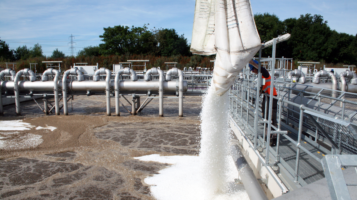
The caustic tank is complete and has under gone wet tests and the safety inspections of the supply chain. A delivery of sodium hydroxide arrived in the week commencing 25 July 2022, putting the team in a good position to commission the plant once Essar send full flows.
The sludge and odour control plant are complete and commissioning will start, once the full loads from Essar arrive in July 2022. The project is due to complete by 19 December 2022.