
Innovative Groundwater Control (2017)
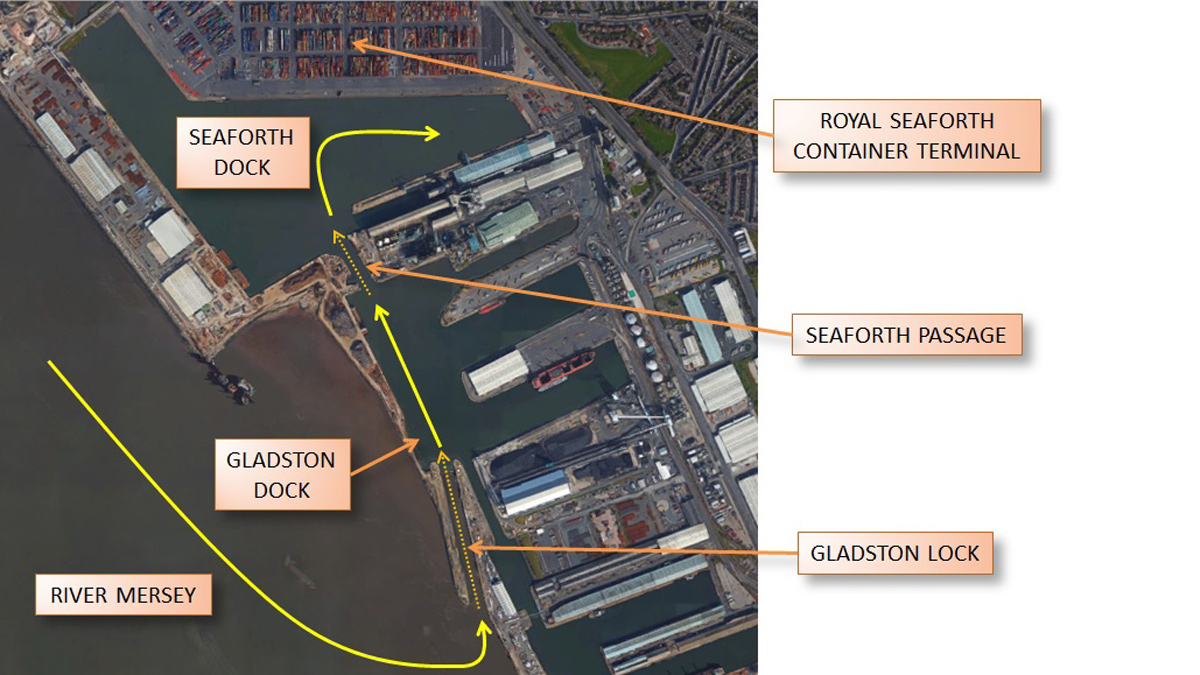
Figure 1. Location of Seaforth Passage - Courtesy of OGI Groundwater Specialists Ltd
Peel Ports required the widening of the Seaforth Passage (Figure 1) within the Royal Seaforth Dock at the Port of Liverpool. The increasing size of modern vessels led to a need to increase the width of the Seaforth Passage, in order to improve the turnaround times for the larger vessels within tidal windows. Farrans Construction Ltd was appointed the £11m contract to carry out the work to widen the passage from 40m to 60m. This paper details the innovative groundwater controls that were necessary to reduce groundwater pressure around the cofferdam.
Project challenges
The Passage widening works included a number of significant challenges, including re-routing of electrical and water services, making provision for future electrical and fibre-optic services around the port, demolishment of the existing quay wall and construction of a new quay wall.
However, perhaps the biggest challenge, was to extend a 3m diameter storm water sewer connecting the Liverpool storm drainage system with an existing outfall. The sewer “siphon” runs directly under the Seaforth Passage (see Figure 2 below), with an up-shaft and down-shaft either side of the Passage, creating a siphoning effect.
Throughout the works, both the sewer and the Passage were to remain ‘live’, i.e. flow of effluent would continue through the sewer and container ships would continue to access the Seaforth Dock via the Seaforth Passage. Extending the siphon pipe would require excavation to a depth of 20m below reduced ground level (circa 23.5m below original ground level), alongside the original sewer up shaft, within a retaining wall cofferdam.
The original up-shaft had to be intercepted at high level and the effluent flow diverted around the cofferdam and back to the main sewer further downstream. Excavation could then take place within the cofferdam to break out the original sewer at low level, install the horizontal siphon pipe extension and to construct the new vertical up-shaft.
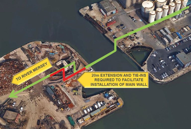
Figure 2. Required sewer siphon extension – Courtesy of OGI
Groundwater control
Being so close to the quay, groundwater pressures were very high. To prevent failure of the combi-wall, the cofferdam designers required significant lowering of the groundwater pressure around the cofferdam.
Construction of a combi-wall cofferdam, designed by Royal Haskoning, was required to -14mCD from a ground level of circa 13mCD, with an internal excavation formation at -10.5mCD, and external excavation to 4mCD. The structural design required the groundwater piezometric head outside the combined structure to be reduced to -9mCD in the lower aquifer, and to +3mCD in the upper perched aquifer, including head within the clayey sand, which is sandwiched between the two clay layers.
The piezometric head profile prior to dewatering and that required by Royal Haskoning are shown in Figure 3.
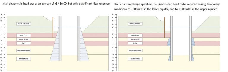
Figure 3. Original piezometric head profile (left) vs that required by the Structural Designer (right) – Courtesy of OGI Groundwater Specialists Ltd
Design and installations phases
The groundwater control system was designed and installed in two phases as described below:
Phase 1: Involved installing, pumping and monitoring from 5 (No.) deep wells (the minimal number of test wells required to reduce the groundwater pressure based on the geological and hydrogeological data available). Test pumping and monitoring of the impact on groundwater pressure was carried out and the scenario was mathematically modelled by OGI using the SEEP/W finite element model.
The following conclusions and solutions were drawn:
- The initial 5 No. deep wells successfully lowered the piezometric head in the lower aquifer to between -5mCD and -6mCD, but fell short by 4m of the required target level of -9mCD. The primary reason for this was that the groundwater within the Sand & Gravel aquifer was effectively perched above the lower permeability sandstone aquifer.
- Using a finite element model, calibrated against the test pumping results, OGI determined that additional deep wells would provide some further lowering of the piezometric head, but that the benefits would have diminishing returns (Figure 4 below), requiring an excessive [circa 36 (No.)] additional deep wells. In practice, this number of wells would be impractical. Not only would it be very costly in terms of installation and running costs but each pump requires a power cable and discharge pipe, and so would occupy a huge amount of surface space on what was already a very congested site, getting in the way of other site activities.
OGI also recognised that the risks associated with relying exclusively on active external pumping were considerable. Any loss in pumping would lead to a rapid rise in piezometric head within minutes and this could cause structural failure of the cofferdam or ground heave.
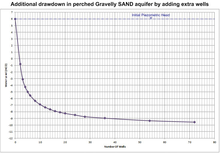
Figure 4. Graph of water level vs number of wells – Courtesy of OGI Groundwater Specialists Ltd
Phase 2: To further lower the existing piezometric head to reduce lateral stress from pore water pressure, required a non-traditional approach. The design essentially consisted of a passive dewatering system to allow groundwater to drain under gravity into the structure via a series of lateral drains which are installed through cut holes within the sheet pile wall sections of the combi-wall.
The design comprised the following items:
- Continued pumping of the 5 (No.) external deep wells installed outside the combi-wall.
- 10 (No.) shallow horizontal passive pressure relief wells through the combi-wall into the upper aquifer.
- 3 (No.) deep vertical active/passive pressure relief wells inside the combi-wall.
- 40 (No.) shallow inclined passive pressure relief wells through the combi-wall into the lower aquifer.
Groundwater pressure outside the cofferdam was monitored throughout the installation stages to ensure the safety of the cofferdam and those working within it.
The system was installed in the following stages as follows:
STAGE 1: External deep wells
- The 5 (No.) deep wells, located outside the combi-wall, installed with borehole pumps were used to partly lower the water level and to assist the subsequent stages.
STAGE 2: Horizontal pressure relief wells into upper aquifer
- From excavation level at -1.00mCD, 10 (No.) horizontal drains were installed through the combi-wall into the upper aquifer.
STAGE 3: Internal active/passive vertical pressure relief wells
- 3 (No.) vertical pressure relief wells (PRWs) were installed inside the cofferdam from -1.30mCD.
- Vertical PRWs were cut down as excavation progressed.
- When excavation reached -5.50mCD, pumping commenced from vertical PRWs.
STAGE 4: Inclined pressure relief wells
- From an excavation level at -5.50mCD, the first set of inclined PRWs was installed through the combi-wall.
- Second set of inclined PRWs were installed at -8.00mCD.
- Third set of inclined PRWs were installed at -9.50mCD.
- Fourth set of inclined PRWs were installed at -10.50mCD.
- Vertical PRWs continued pumping and were cut down as excavation progressed. Figure 5 (below) shows installation of PRWs.
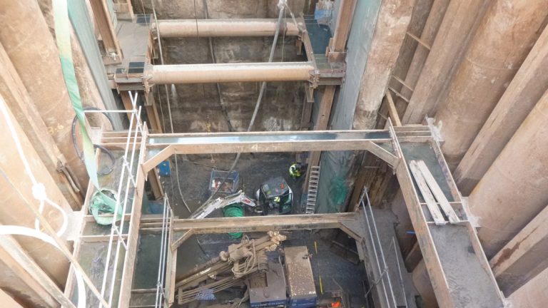
Figure 5. Inclined drilling within the cofferdam excavation – Courtesy of OGI Groundwater Specialists Ltd
STAGE 5: Drainage layer at final excavation level and hydraulic connections
- A clean stone drainage layer, including perforated drainage pipe, was installed to create hydraulic continuity with the pressure relief system.
- Sheet pile in-pan well casings were installed hydraulically connected with the drainage layer.
- Groundwater bleeding from the inclined PRWs was collected by the drainage layer to a boxed sump installed with a sump pump.
STAGE 6: Reinforced concrete base slab
- Construction progressed with an impermeable geomembrane, concrete blinding and reinforced concrete base slab. When the reinforced concrete slab cured, pumps from vertical PRWs were removed. The vertical PRWs were sealed over the slab layer, but remained hydraulically connected with the underlying drainage layer (Figure 6 below).
- Groundwater bleeding from the vertical PRWs and the lower row of inclined PRWs was collected by the drainage layer to the boxed sump.
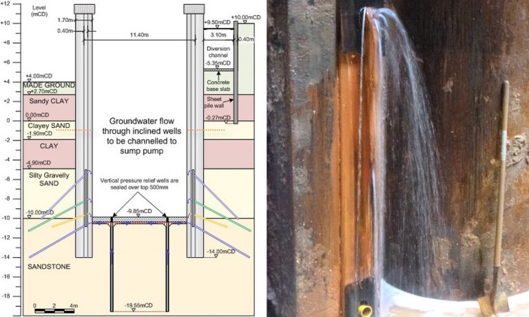
(left) Figure 6: Section detail showing active pumping wells, vertical and inclined pressure relief wells & drainage layer and (right) Figure 7: Groundwater depressurisation in action – Courtesy of OGI Groundwater Specialists Ltd
STAGE 7: Construction of sewer connection and siphon shaft
- Before mass concrete was poured, the inclined PRWs installed at -8.00mCD and -9.50mCD were connected to the vertical in-pan casings to channel the water to the boxed sump. The sump was extended using man-hole rings to enable sump pumping to continue. Once mass concrete was cured the sump pump was removed and the man-hole backfilled.
- Groundwater was allowed to bleed through the vertical in-pan casings and inclined PRWs to the surface of the mass concrete (see Figure 7 above).
Benefits of OGI’s solution
There are a number of benefits for utilising OGI’s solution including:
- OGI’s design successfully reduced groundwater pressures on the outside of the cofferdam, to the design profile required for a safe and stable cofferdam.
- The system enabled construction of the siphon extension and new up-shaft, free of the risk of cofferdam collapse or ground heave due to the rapid rise in external water pressure due to active pump failure.
- OGI’s approach dispensed with the requirement to install a large number of deep wells and to run a large number of active pumps, saving the main contractor considerable expense.
- The installed system occupied minimal space, so had minimal impact on excavation and other site activities.
- The upper aquifer was further depressurised using inexpensive and easy to install plati-drains.
- Only three additional deep active wells were required to protect the base of the excavation as it advanced, and these were converted to passive depressurisation wells when final excavation level was reached.
- Although a total of 50 (No.) inclined pressure relief wells were installed as excavation advanced, these wells were to shallow depth only, so were inexpensive to install and with no running costs.
- The water ingress was handled by channeling the water to a single sump.
- The simple nature of the solution required fewer specialist components and equipment.
- The siphon extension was successfully completed on programme.
Summary
It is important to recognise that without the trust, support and clear lines of communication established with Farrans Construction and Royal Haskoning, the success of this project could not have been achieved. OGI’s role in this project was awarded the following recognition:
- 2016 British Construction Awards: ‘Highly commended’, in the category of Temporary Works.
- 2017 Ground Engineering Awards: ‘Highly commended’, in the category of Technical Excellence.
The judges’ comments described OGI’s approach as:
“A counter-intuitive but simple and elegant solution to a difficult groundwater problem that would have otherwise rendered the project virtually unachievable. This was impressive in its effectiveness and demonstrated a high degree of trust and collaboration”.