
Ringsend Main Lift Pumping Station (2021)
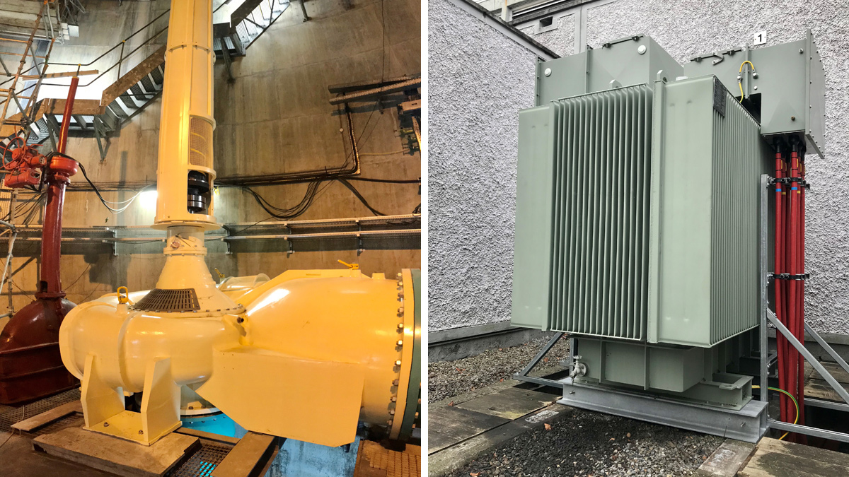
(left) Installed 630kW Bedford Pump and (right) the new CG Power Systems transformer unit - Courtesy of EPS Group
Ringsend Main Lift Pumping Station (MLPS) is located at Pigeon House Road, Ringsend, Dublin 4 and forms a critical part of the overall Dublin Drainage Network. It is operated by Dublin City Council and is under the joint control of the Local Authority and Irish Water. The MLPS pumps unscreened, unfiltered wastewater from the city centre, Rathmines & Pembroke, Grand Canal and the East Wall sewers to Ringsend WwTW. The pumping operation significantly reduces the risk and impact of flooding to Dublin City as it delivers the network stormwater to the WwTW. The station upgrade is required due to the risks associated with its current operability and the potential of flooding associated with the potential failure of pumping equipment as it approaches the end of its asset life.
Existing works
The pumping station originally consisted of four Allen Gwynne fixed speed pumps, each driven by 700kW motors which were installed in 1985, plus two Bedford Pumps variable speed pumps installed in 2001, each of which were driven by a 500kW motors. The pumps operated on a duty/assist/assist/assist/assist/standby basis with an approximate maximum total pumping capacity of 12.8m3/s to Ringsend WwTW.
Project scope
EPS Group were appointed as the main contractor on the project following a comprehensive tendered procurement process led by Irish Water. A contract valued at €6.8m was signed in March 2018.
The project scope is to replace the existing pumps with 6 (No.) 630kW variable speed pumps, each capable of discharging up to 3.6 m3/s. This configuration was selected to achieve optimum energy efficiency and maximise unit life and provide optimum long-term operations and maintenance efficiency. The pumping station has a nominal output capacity of 18m3/s, taking into account the designed N-1 redundancy.
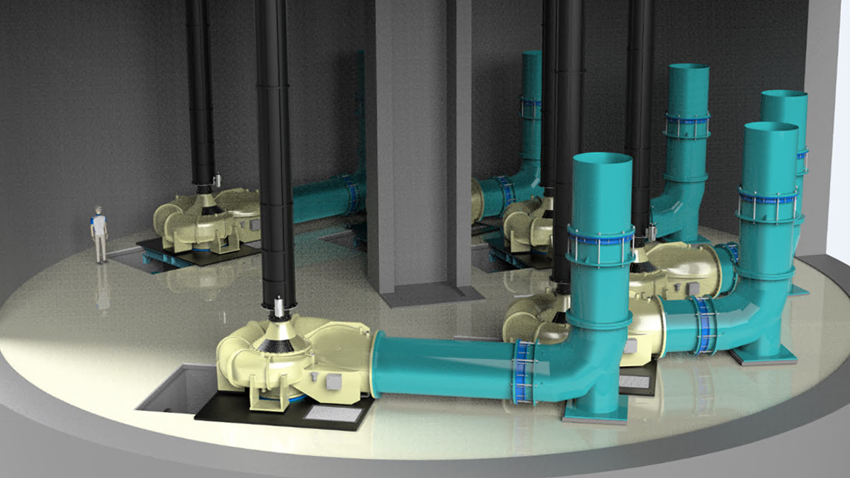
Rendered 3D view of Ringsend MLPS – Courtesy of Bedford Group
The scope of works also includes the installation of 4 (No.) DN1200 discharge siphons, replacement of 2 (No.) 10/20kV-3.3kV transformers and 2 (No.) 3.3kV-400V transformers, installation of MV switchgear and the upgrade of instrumentation, including all associated low voltage works.
A new ICA system is being installed on site to automatically control the pumps and monitor condition of all relevant electrical equipment and instruments. Auxiliary equipment, including ventilation and odour units, have also be upgraded in order to comply with current specifications.
Ringsend MLPS: Supply chain – key participants
- Main contractor: EPS Group
- Employer’s representative: JB Barry and Partners Ltd
- Hydraulic design: Royal HaskoningDHV
- Mechanical design & installation: EPS Group
- EICA Design & installation: SSE Airtricity Utility Solutions
- Odour & ventilation systems: Anua Clean Air UK
- Pump supply & installation: Bedford Pumps
- Motors: WEG
- Carbon shafts: Bibby Turboflex
- Pipework & fabrication: JK Fabrications Ltd
- Siphons & pipework: EPS Group
- Siphon break valves: Apex Flow Control
- Variable frequency drives: Rockwell Automation
- Transformers: CG Power Systems
- MV switchgear: Siemens
- LV & ICA panels: Manutec
Health & Safety and challenges
This project is a critical part of the Dublin Drainage Network, operating on a 24/7 basis. The MLPS had to remain fully operational throughout the project – with 5 (No.) pumps available at all times. MV supply, LV supply and pump assets had to be removed according to a pre-planned phasing programme.
The 35+ year-old transformers, MV switchgear panels and pumps were obsolete, in the end of their life-cycle and with identified safety issues. Detailed documented isolation procedures, with certified safety authorised personnel, were implemented on site to ensure all assets were taken offline safely and correctly.
The pumps, including their volutes weighed approximately 3 tonnes and were replaced at a depth of 11m below ground, which required comprehensive fall protection systems to be put in place and for the number of personnel working in the area to be limited.
The onset of the Covid-19 pandemic in the middle of the installation added a further level of safety complications for EPS to address. These were overcome by the imposition of strict Health & Safety measures implemented by all parties involved in the project, allowing programme disruption to be minimised.
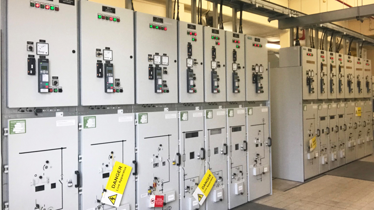
New MV switchgear panels – Courtesy of EPS Group
Electrical installation
The upgraded electrical installation maintained the existing Schneider 10kV SM6 Switchgear, but all remaining electrical systems fed by this panel were replaced.
The project scope comprised the replacement of Transformers T1 and T2 with 2 (No.) new 10/20kV-3.3kV 5000kVA CG Power Systems transformers. These in turn feed the new Siemens MV switchboard, which now includes additional breakers for the generator supplies. The MV switchboard supplies the 6 (No.) new 630kW variable frequency drives (VFDs) and the generator panel (DN3 and DN4 connection). The 630kW VFDs feed and control the pumps, as well as monitoring their operational condition.
Transformers T3 and T4 were replaced with 2 (No.) new 3.3kV-400V 250kVA CG transformers to supply the LV and ICA panel, which subsequently feeds all low voltage ancillary systems – i.e. gas detection, gas suppression, odour unit, ventilation unit, fire alarm system, ICA, lighting, control monitoring and instrumentation.
Pump assemblies
The project main driver is to improve the energy efficiency and reliability of the pumping station. The pumps supplied were 6 (No.) Bedford Pumps 630kW pumps, connected to 630kW WEG Motors by a laser-aligned carbon shaft. These pumps are electrically fed through Rockwell Powerflex 6000 variable frequency drives which allows the pumps to run at variable speeds to adjust to incoming flows from the inlet sump.
The 630kW volute pumps were fully designed, manufactured and factory inspected and tested by Bedford Pumps to demonstrate a maximum pumping capacity of 3.6m3/s each, and energy performance compliance.
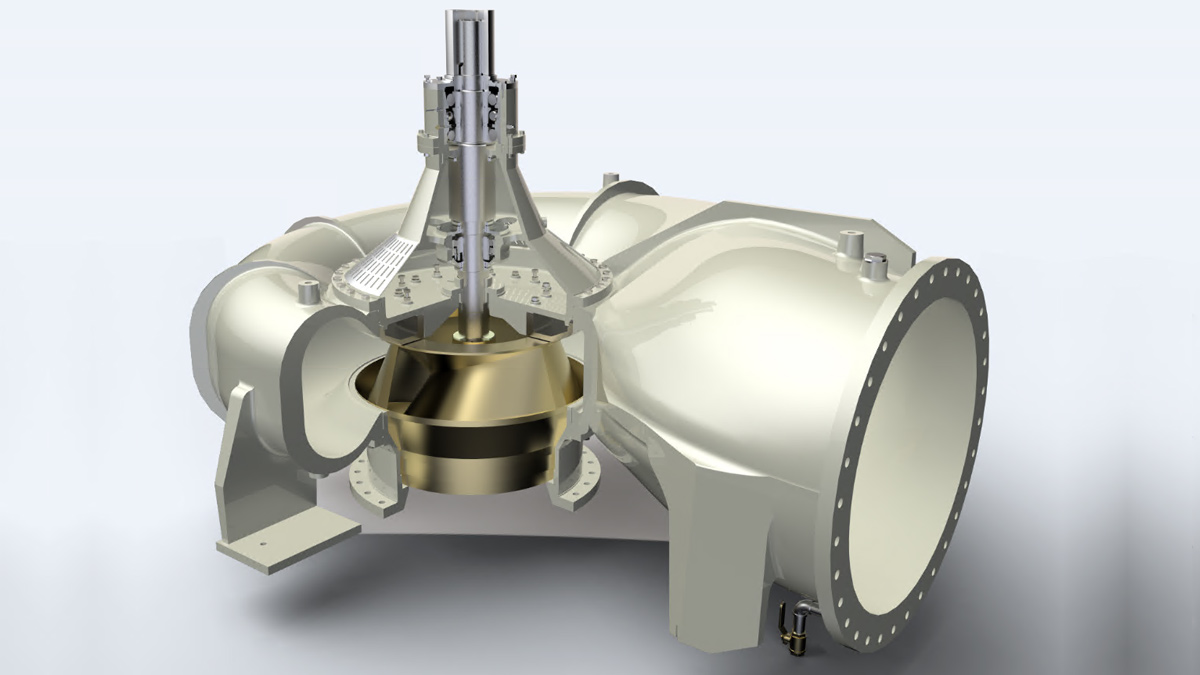
Cutaway render of a 630kW pump – Courtesy of EPS Group
All pumps were installed on site with a full condition monitoring system directly linked to the variable frequency drives and automation system. This system facilitated monitoring in real time of the temperature and vibration of bearings and motors, systems torque and seal pressure.
A Doppler flow meter and suction and discharge pressure transducers were installed in each pump to allow for automatic control. Any values above the defined alarm and trip set-points will generate an alarm to the operator HMI.
Siphon improvements
The existing site had already two siphons installed and connected to the outlet of the 2 (No.) 500kW Bedford Pumps variable speed pumps. The remaining 4 (No.) 700kW Allen Gwynne fixed speed pumps were connected to a DN1200 pipework that would discharge directly to the outlet channel through a vertical pipework and bellmouth without siphon recovery.
In order to improve the pump efficiency and utilize existing good condition equipment and pipework, the 2 (No.) existing DN1200 siphons were retained and remaining pipework arrangements were upgraded to include 4 (No.) new DN1200 siphons, installed on the discharge side of the remaining pumps. Above each siphon a fully-automated DN200 Rotork-actuated valve was installed to allow the siphon to prime on pump start and to break on pump stop.
The siphons allow the system to operate at a lower dynamic head, resulting in considerable savings on overall site energy consumption.
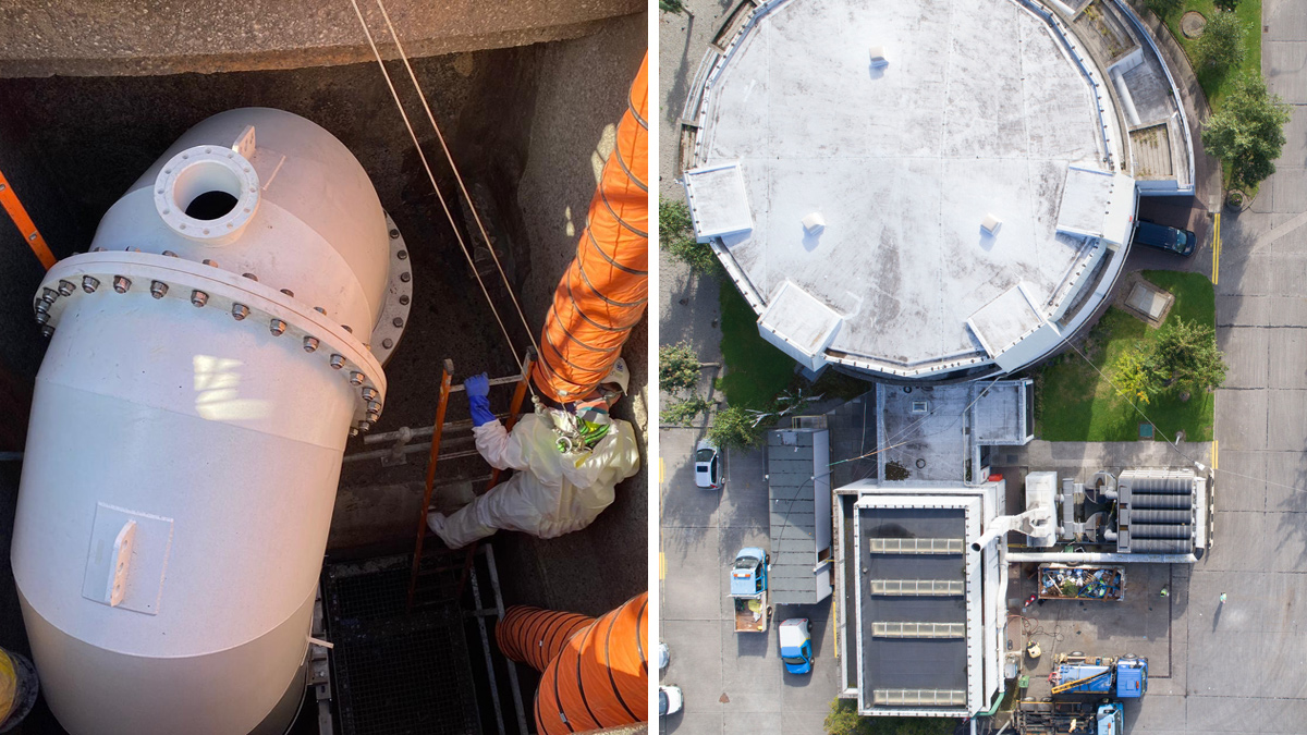
(left) Siphon pipework installation and (right) aerial view of the Ringsend MLPS site – Courtesy of EPS Group
Automation & control philosophy
The scope included the design and supply of a brand new Allen Bradley PLC. The main control philosophy premise is to maintain a defined operator-adjustable range of wastewater inlet sump levels, and to control the pumps to operate efficiently in accordance with the pump curves. This allows the duty pump to start when the inlet sump level set-point is achieved and ramp up and down to maintain this level. If the level rises/lowers above/below the set-point band, then required assist pumps will start/stop accordingly.
The system was designed to accept signals from power meters and status indicators for all electrical systems and instrumentation, and to record, display and trend condition monitoring, levels, flow, suction and delivery pressure, energy performance indicator and energy consumed for each pump.
The system also displays and records overall energy consumption, motor hours, pump starts and stops and overall daily energy consumption costs. Any abnormal variation to the normal control monitoring set-points or equipment operation generates an alarm in the system for the operator to acknowledge and assess.

Ringsend WwTW – Courtesy of Royal HaskoningDHV & Barrow Coakley
Conclusion
The Ringsend Main Lift Pumping Station project delivery progressed despite the installation challenges and Covid-19 restrictions that arose during the works.
Working on a critical drainage system while maintaining its operation involves constant forward planning, monitoring and reviewing. Some key work tasks had to be executed during dry weather which brought dependencies and uncertainty to the planning process.
The scope of supply has captured and significantly enhanced the key components of the pumping station. Lessons learned were captured from past projects and when overcoming many of the challenges on site, and these have contributed to the successful and safe installation of more efficient and reliable equipment at the MLPS. This in turn has enabled EPS and the client to develop a better understanding of the overall system potentials and limitations in the operating phase.