Rothbury STW (2022)
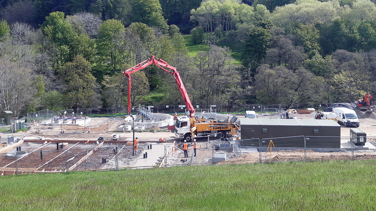
Rothbury STW under construction - Courtesy of MMB
Rothbury Sewage Treatment Works is an unmanned Northumbrian Water site located 13 miles north-west of Morpeth, Northumberland. It is on the western valley slope of the River Coquet, a designated Site of Special Scientific Interest. The area is a popular year-round holiday destination with several caravan sites within the catchment. The original works dates from c.1935 with modifications carried out in 1992, 2002 and 2017. The treatment works is on two terraced levels constrained linearly between the river and the toe of the steep valley side. The majority of flow is pumped to the works. The ongoing £4.3m upgrade will increase the capacity of the works, replace ageing assets and improve the site’s operational and performance issues.
Existing works
Up to 60 l/sec arrives at the elevated inlet reception chamber, passes through an above-ground combined package screen/grit removal plant and into a balance tank, where a hydro-brake controls the maximum flow-to-treatment and, during storms, a high-level weir is overtopped to the storm tanks.
Flow-to-treatment passes via an MCERTs magnetic flow meter to two 4.4m square Dortmund pyramidal primary settlement tanks (PSTs). A dosing siphon feeds four 15.4m diameter blast-furnace slag media percolating filters, and final settlement is provided by a 4.4m square Dortmund pyramidal tank and a 7.6m diameter circular settlement tank.
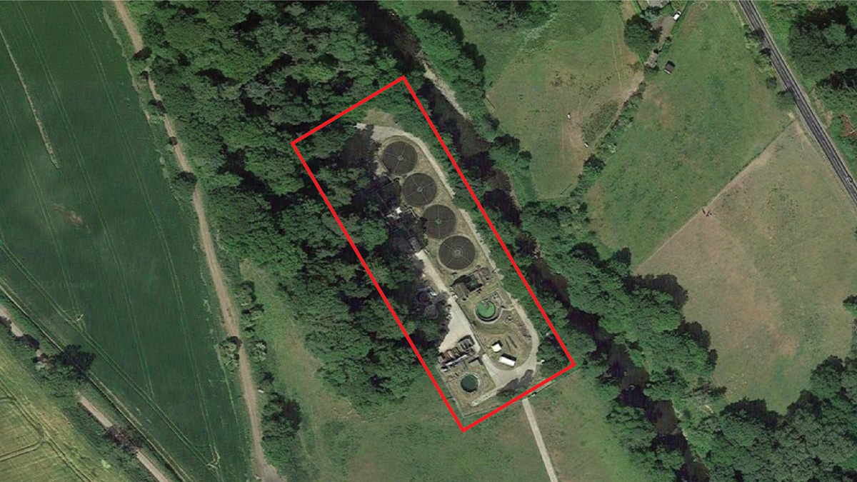
Google Maps view of Rothbury site – Courtesy of MMB
The treated effluent normally gravitates through a final effluent pumping station to the combined sampling/outfall chamber before discharging to the river, but when the river is in spate, the FE pumps lift the flow to overcome the high river levels. In 2017 two original sludge storage tanks were replaced by a single 4.3m diameter glass-coated tank. Two rectangular storm tanks provide a settlement volume of 144m3. A control building also houses the site returns pumping station. The site’s wash-water system comprises a potable water break tank with a booster set supplying hose-points.
Overhead 22kV power lines and a BT cable cross the site, which falls within the Environment Agency’s Flood Zone 3; the percolating filters, humus tanks, recirculation and final effluent pumping stations located on the lower terrace being most at risk.
Project investment drivers
- WINEP U-IMP5: Flow to full treatment to be increased to 3PG + IMAX + 3E but no less than maximum daily flow with sufficient margin to empty the storm tanks ASAP.
- Undersized assets: A capacity assessment indicated that increased flows from catchment growth will make the process units undersized with respect to maintaining compliance with the permit.
- Asset deterioration: A number of the existing assets were aged and deteriorated. The main works MCC dated from 1992 and much of the electric cabling needed to be replaced.
- Operation and performance issues posed risk to compliance: Accuracy of FFT flow control; screenings bypassing the inlet screen into the downstream grit removal system; existing PSTs difficult to de-sludge; an additional sludge storage tank was required.
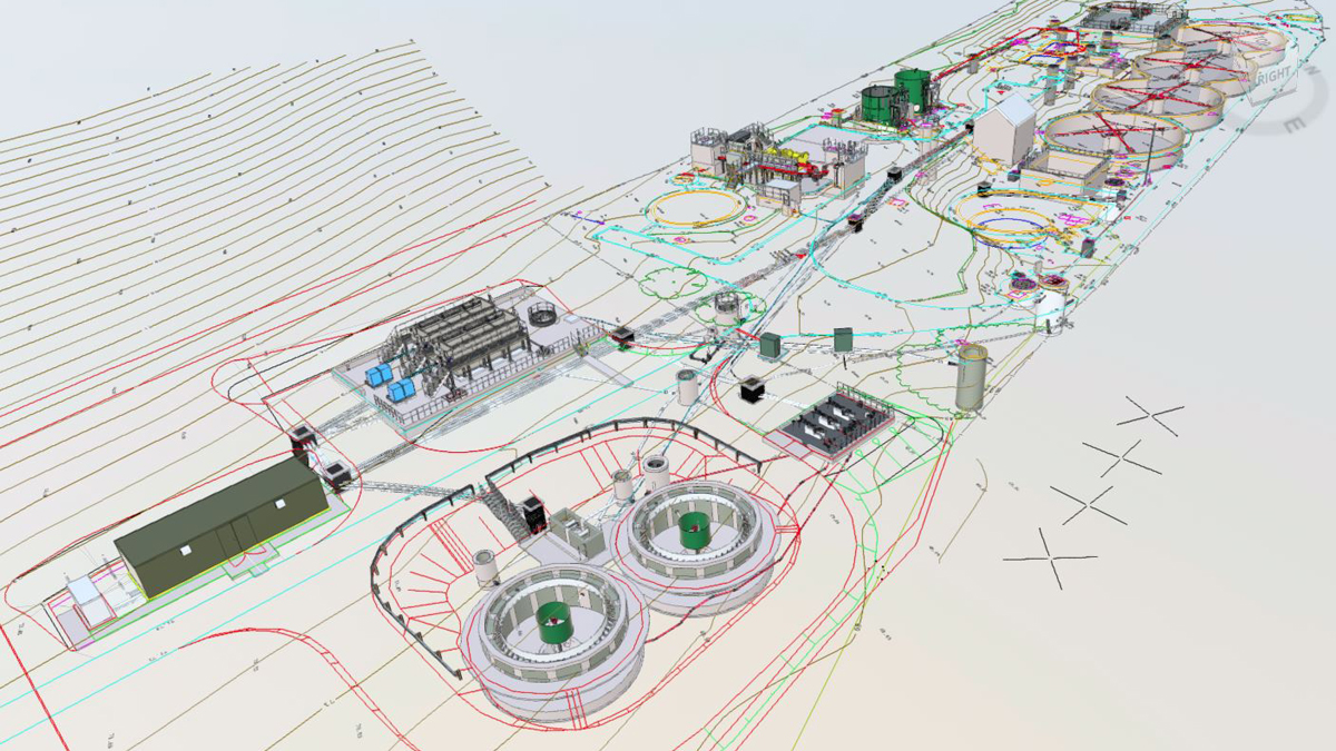
3D model of the works – Courtesy of MMB
Flow calculations
A detailed analysis of the catchment was undertaken to verify the existing resident and holiday population and the proportion of combined/separate sewers. Future population was collated from local council new development plans with a 10-year design horizon. A new pumped transfer from an adjacent catchment also contains a caravan park and contributes to growth. Flow, sample and rainfall data from 2010-2019 was analysed, and an increased infiltration rate (IMAX) was adopted for the flow calculations.

Design horizons
Notional solution and target cost contract
The asset needs statement listed: a new inlet works, balance tank, flow control and FFT MCERTs flow meter; two larger circular PSTs with auto-desludging; two HSAFs (hybrid submerged aerated filters) units operating in solids filter mode to reduce suspended solids and associated BOD; provision of a second sludge storage tank; an additional 72m3 of storm tank storage; replacement of the works MCC; site-wide electrical refurbishment; and access improvements including relocation of the final effluent sample point.
An investigate and define contract was let and an agreed solution developed, costed and validated, comprising: the retention and refurbishment of the existing packaged inlet works, with modifications to the existing inlet reception chamber, pipework and balance tank; and the provision of additional storm storage by raising the outlet weirs of the existing storm tanks.
A design and construct contract was then let under the NEC3 Option C with a target cost of £4.34m.
Surveys and geotechnical investigation
Surveys to assist the design included 3D surface spot levels, ground penetrating radar for buried services and a laser scan point cloud. Past and new ground investigations comprising trial pits, windowless samples and boreholes proved the ground to comprise glaciofluvial and alluvial deposits underlain by medium-to-strong Fell Sandstone Formation bedrock – the level of which was mapped into the 3D ground model of the site, as well as groundwater within the bedrock.
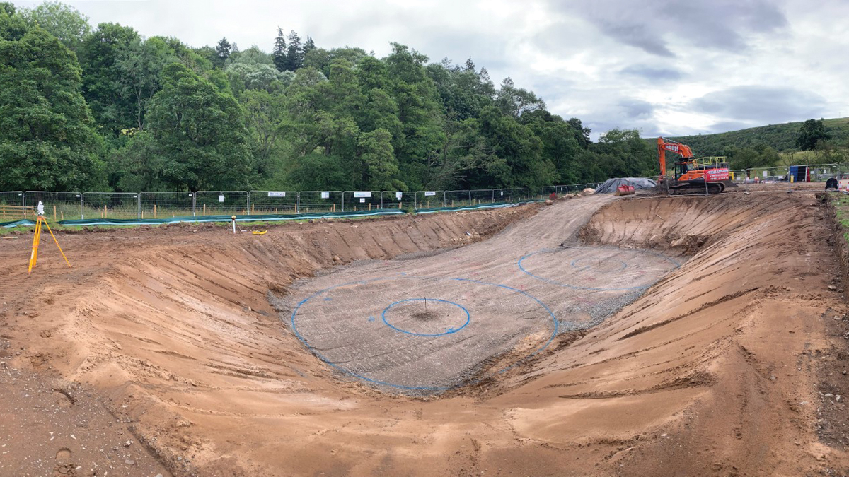
Temporary excavation for new primary tanks – Courtesy of MMB
Landowner agreement and planning application
The site required an extension outside the existing boundary to accommodate the new assets. Agreement was obtained and, in order not to delay delivery of the project, a planning application was submitted before the design and construct contract had been awarded, based on the outline design layout.
During detailed design, a non-material amendment was secured, exchanging the location of the new HSAFs and control building. The change resulted in an improved site layout whilst reducing the length of pipe and cable duct-runs between the existing site and the new extension.
Rothbury STW: Supply chain – key participants
- Principal designer & contractor: Mott MacDonald Bentley
- Packaged inlet works refurbishment: Huber Technology
- Precast concrete primary tanks: FLI Precast Solutions
- Half bridge scrapers: DD Engineering Ltd
- Biological filter arm replacements: IQ Engineers Ltd
- Tertiary treatment HSAF plant: FLI Water Ltd
- Above ground sludge storage tank: Stortec Engineering Ltd
- Temporary works/shoring: MGF Ltd
- Sludge mixer: STEM Drive
- Electrical design & installation: Intelect Ltd
- Systems integration: IDEC Technical Services
- Control panels: Blackburn Starling Ltd
- Control panel kiosks: Morgan Marine
- Control panel kiosks: Kingsley Plastics
- HSAF feed & recirculation pumps: Xylem Water Solutions
- In situ reinforced concrete & shuttering: JM Jackson Ltd
- Precast concrete U-channels: FP McCann
- Metalwork: JHT Fabrication Ltd
- Temporary flow balance tank: TerraTank Ltd
- Temporary works over pumping: Selwoods
- Scaffolding: Interlink
- Tree pruning: Premier Tree Services
- Fencing: Stuart Marley
- Ultra3 PVC-U gravity pipes: JD Pipes
Existing inlet works modifications
A high-level bypass weir in the inlet reception chamber has been lowered and metal weirs inside the packaged screen raised, to ensure flows will automatically by-pass the screen in the event of blockage. The packaged inlet works has been mechanically and electrically refurbished, and the outlet pipework upsized to achieve the unit’s maximum throughput (65 l/s). The balance tank has been re-benched to a new actuated flow-control penstock, and new platforms will improve access to the inlet works for inspection and maintenance.
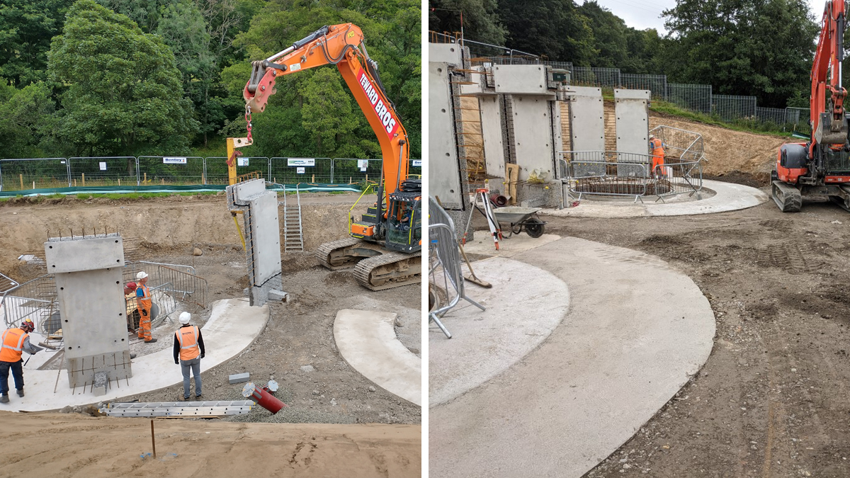
Installation of PCC wall units for the PSTs – Courtesy of MMB
New primary settlement tanks (PSTs)
Screened and de-gritted flows will pass via a new MCERTs compliant electromagnetic flow meter to a new PST distribution chamber and two 7.0m diameter radial flow tanks. Semi-precast concrete designs were adopted for these structures to save on construction time; the precast units being simplified to make them easier to fabricate and lighter to handle on site.
A ground-level positive displacement pumping station will transfer co-settled primary sludge and scum to the sludge storage tanks. The pump station layout was re-used from a previous project, with duty/standby sludge pumps and a dedicated scum pump being identical, for standardisation of maintenance, and valved for complete inter-operability.
Biological filters
The existing 250mm diameter dosing siphon and the distributor machines to all four filters are being replaced to accommodate the increase in FFT.
Tertiary HSAFs
Instead of constructing an additional humus tank, two tertiary treatment solids removal HSAFs have been installed to polish the final effluent to the required standard.
A reinforced concrete base slab was constructed on a ‘cut-and-fill’ formation into the valley slope, to accommodate the HSAFs and the new final effluent sampling chamber (fitted with an auto-sampler and temperature and turbidity probes). The HSAFs were delivered to site pre-filled with media and lifted into place.
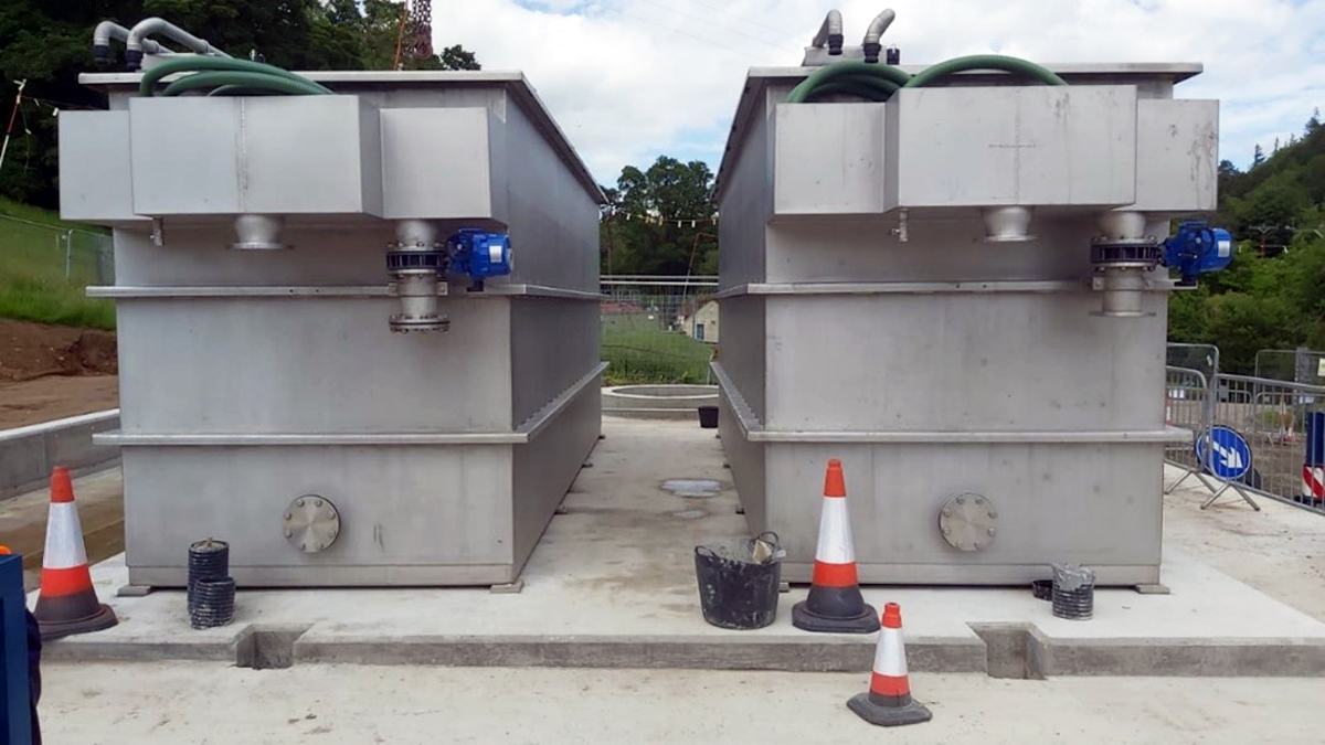
HSAFs – Courtesy of MMB
Tertiary treatment feed pumping station
The existing final effluent pumping station is being converted into an interstage pumping station to lift flows to the new tertiary treatment HSAFs. The existing wet well and valve chamber will be retained and the fixed speed duty/standby submersible pumps will be replaced with higher head variable-speed pumps. The existing station pipework requires upsizing and a new rising main will be provided to the HSAF plant.
Storm tanks
The required increase in storm tank capacity will be achieved by raising the outlet weirs of the existing tanks. Repairs will be carried out to the dividing wall and improved access will be provided to existing valves, mixers and lifting equipment.
Sludge storage tank
A second sludge tank is required to increase the site’s storage capacity and the existing STEM Drive mixing system has been extended to the new tank.
Washwater
The existing leaking potable wash-water distribution system and hose-points are being replaced across the site.
Challenges installing pipework and cable duct runs
The need to extend the site along the valley side resulted in 530m of new gravity, pumping and washwater distribution mains, and 215m of cable duct-runs being installed between the original site and the new site extension, in sloping ground, whilst avoiding clashes with existing infrastructure and minimising the need to excavate through sometimes shallow bedrock. A 3D ground model of the site proved to be essential in confidently designing the alignments and levels of the new pipe and duct-runs.
Electrical and ICA scope
The maximum demand for the existing site, estimated at 54kVA, would increase to 85kVA and the existing pole-mounted transformer, supply cable, fuse, meter and kiosk were upsized to suit. Given the remote location for responding to power interruptions, a standby generator has been provided for the new essential equipment.
The existing works MCC will be replaced by a new front access/bottom entry full walk-around MCC, housed in a GRP LPCB3-security rated kiosk located out of the Flood Zone. A door-mounted HMI will allow operators to monitor and control the whole works. A compact Logix PLC will communicate with a Talus T4e outstation via a Modbus network for onward transmission of plant status and alarm conditions. The existing inlet works MCC will be retained but the existing site will be provided with new instruments and cabling.
Retention/removal of items at the existing works
The main site returns pumping station, filter recirculation pumping station and the two humus tanks are being retained, with nominal improvements. A number of historically redundant items will be decommissioned and demolished/removed. The existing site perimeter fence will be extended with a new access gate.
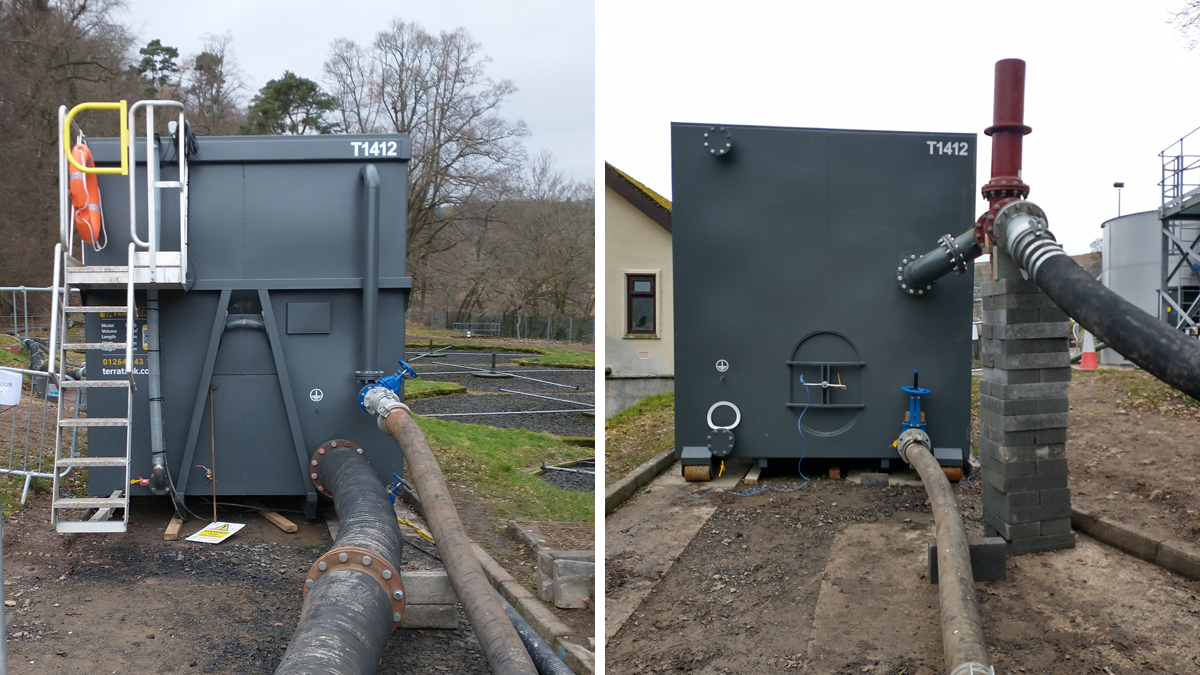
(left) Inlet end and (right) outlet end of the temporary works flow balance tank – Courtesy of MMB
Temporary works
In addition to the usual design of temporary roads, hard-standings for site compounds and crane pads for lifting operations, several temporary flow management/over-pumping designs were required to ensure the works remained operational throughout the construction period. These included when the FE pumping station is converted into the HSAF feed pumping station, when keeping the biological filter media wetted during phased replacement of the filter distributors, and when the inlet works was taken off-line and bypassed for refurbishment and modification.
In the latter instance, the original proposal had been to divert all flows arriving at the works to an existing below-ground tank from which two sets of pumps would forward flows (a) for treatment and (b) to the storm tanks, as appropriate. However, during planning meetings it became clear that this proposal carried high risk due to possible pump blockages/failure or power outages, requiring not only duty/standby pumps but also duty/standby power generators, fully automated control, fault signals/alarms, overnight/weekend supervision, and personnel on emergency call-out standby.
The cost of temporary plant hire and running costs were mounting.
The site team came up with a possible alternative gravity-fed system utilising falls in ground levels across the site, and requested the temporary works designer to investigate. Careful hydraulic analysis showed that siting a temporary hired-in screen and an above-ground balance tank at specific levels on the site, combined with appropriately sized overland pipework, meant the proposal would work, and would greatly de-risk the project whilst significantly reducing the hire and running costs of the temporary arrangement.
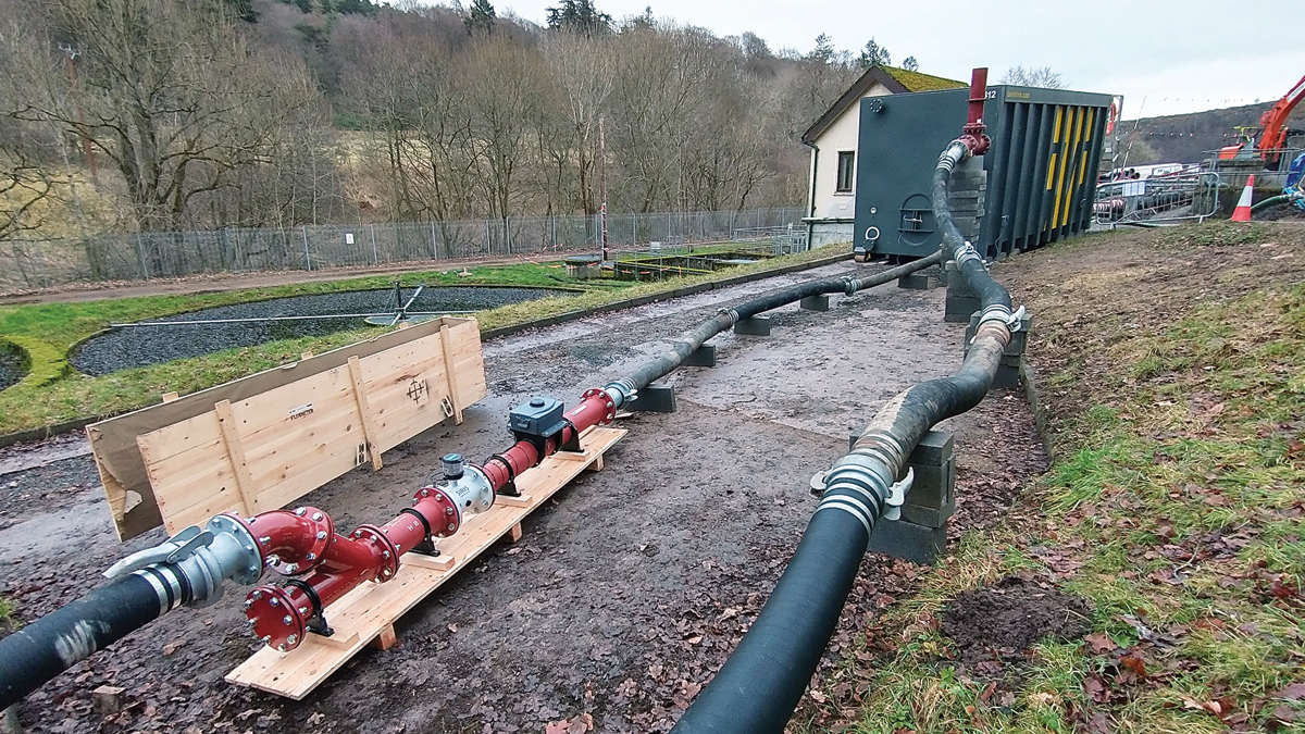
Temporary works flow management: FFT continuation pipe (with MCERTS flow measurement rig) and storm overflow pipe from temporary flow balance tank – Courtesy of MMB
A hired-in mobile 40m3 capacity roll-on/roll-off tank was provided by TerraTank Ltd and deployed as a temporary replacement balance tank. A partly closed outlet valve on the low-level outlet controlled the pass-forward flow-to-treatment, with flows exceeding this backing-up in the tank until a high-level overflow allowed excess flows to spill to the storm tanks.
The fully gravity-flow arrangement worked very well for the duration of the inlet works modifications, with an estimated saving of £50k.
Project efficiencies
Throughout the project, the team has sought efficiencies, and a number have been realised with savings on the target cost: some are described below.
The outline design proposal was to create a ‘terrace’ for the new PSTs by cutting a 1 in 3 slope in the valley side. However, during detailed design, geotechnical analysis showed that it would be possible to steepen the proposed cut to 1 in 2, and 3D modelling of the site showed that by extending this slope to formation level for the new PSTs would allow a temporary open-cut excavation to be used for construction of the tanks whilst still fitting between the existing site access road and the site boundary and SSSI. This avoided the need for a piled and framed temporary works cofferdam, saving £83k in temporary works hire and installation costs.
Inclusion of an access ramp from existing ground level into the excavation enabled the use of the site’s 32 tonne excavator to offload and place the precast wall units (and bridge scrapers), negating the need for the originally planned 150 tonne crane and making a further efficiency saving of £90k.
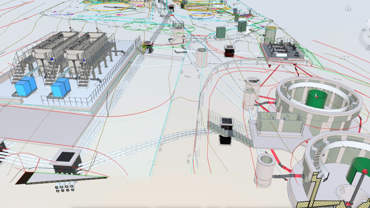
3D model of the works – Courtesy of MMB
Due to the ‘tight’ footprint of the excavation at PST formation level, there was not enough space for traditional strutted plywood to form the outside face of the anti-flotation outstand at base level. Instead, a self-supporting thin-walled form system was used (more commonly used for ground-beams on housing developments). This not only ensured the construction fitted within the available footprint but also saved some £5.7k on traditional timber formwork.
The PST tanks were constructed and water-tested in sequence, re-using the same test water, which was further re-used to water test the new sludge tank, and then again to fill the hired-in temporary balance tank so the open-setting on the outlet valve could be set to pass the correct FFT before overflowing to storm.
Where possible Ultra3 PVC-U structured wall pipe was used for gravity pipes instead of ductile iron or concrete.
MMB has a number of ‘standard product’ designs, to promote efficiency by minimising repeat design of common items. In this case MMB’s standard product for GRP MCC buildings was used, incorporating a bottom access cable trench formed of precast concrete channel units. In addition, a metal frame placed over the units and cast into the in situ concrete floor provided a factory-assembled, perfectly level, right-first-time support for installing the MCC panel.
Simplifying the profile of the precast concrete PST wall units, by replacing the inner concrete wall at the launder channel with a taller GRP weir plate, made the design, detailing and fabrication of the units simpler, and reduced both the overall diameter/footprint to be accommodated on site and the weight for transportation, off-loading and installation.
Packaging the provision and installation of the new sludge tank, floor benching, decant pipework and access platform into one sub-contract reduced the interfaces and de-risked the procurement of this package of work.
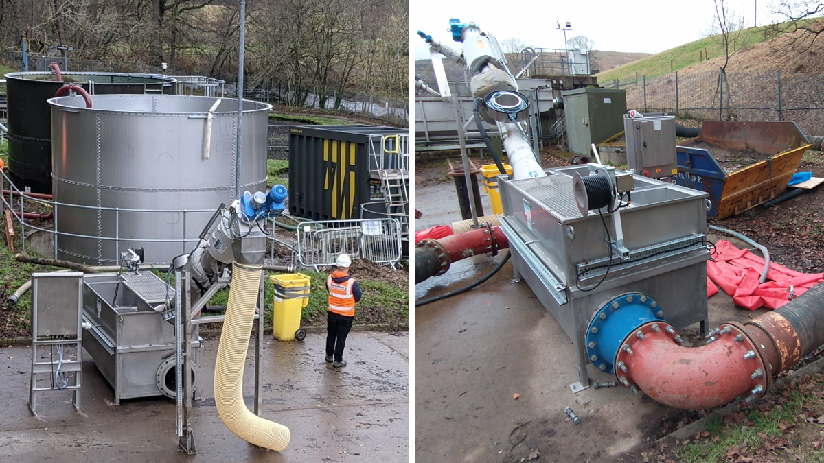
(left) Temporary hire screen and balance tank adjacent to new sludge tank and (right) temporary overland flow diversion pipework from inlet reception chamber to temporary screen – Courtesy of MMB
Other savings were achieved by:
- Adopting shared split-level pipe trenches where possible, to optimise pipeline buildability in the congested narrow site and through shallow rock.
- Use of the same-day modular site-adjustable QMEXX pipe support system for installation of overground pipes (instead of waiting for one-off factory-made-to-measure and galvanised fixed supports).
- Pre-jointing the up-sized flanged 350 diameter DI pipework on the ground for installation at the inlet works in a single lift. Pipework installation was safer, quicker and contributed to a shorter-than-programmed completion of the inlet works modifications, reducing both exposure to risk, and the hire of temporary bypass equipment (screen, overground pipework and TerraTank Ltd).
- Procuring the in situ PST sludge hopper reinforcement as prefabricated welded cages, reducing rebar fixing time on-site by several days.
- Placing an order for the turbidity probe with that for a separate concurrent project, achieving a discount for each project.
- Designing the re-profiled ground levels at the PSTs to also provide the 1 in 100-year river flood compensation storage volume, required by the planning conditions, without needing to provide this separately elsewhere.
- The temporary hardstanding originally constructed for installation of the PSTs has been incorporated into the permanent works for use in future lifting operations at the site.
- The early placement of procurement orders (eg pumps, half-bridge scrapers, MCC building kiosk, new sludge tank) essentially froze the prices in a period of increasing inflation and ensured the items would be available on time for installation on site.
- Straighter pipe/cable duct runs reduced the number of manholes/chambers and the lengths of electrical cabling.
- During detailed design, a non-man-entry laser scan of the FE pump station wet well, carried out from ground level, was used to clarify conflicting information from a previous man-entry survey
- Northumbrian Water and suppliers were given access to the project’s 3D federated model in BIM360 (the common data environment) where the layout and detailed design was developed and information stored.
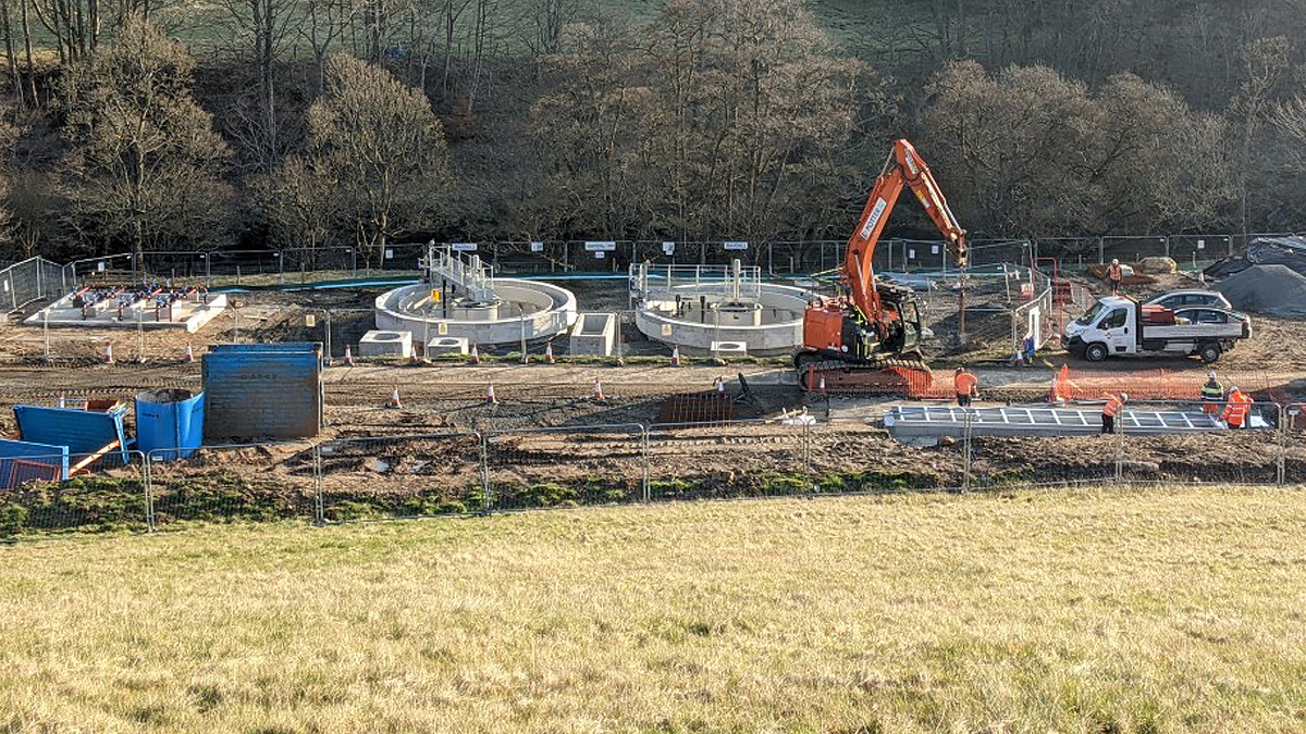
Rothbury STW under construction – Courtesy of MMB
Progress
The design and construct contract was awarded to MMB in December 2020, with the works required to meet the new discharge consent by 31 March 2024. The design team mobilised in January 2021 with the construction team starting on site in June 2021.
At the time of writing (July 2022) design is substantially complete and construction well underway, with commissioning and hand-over due in October 2022, well ahead of the new consent date.


