
Springs Impounding Reservoir (2017)
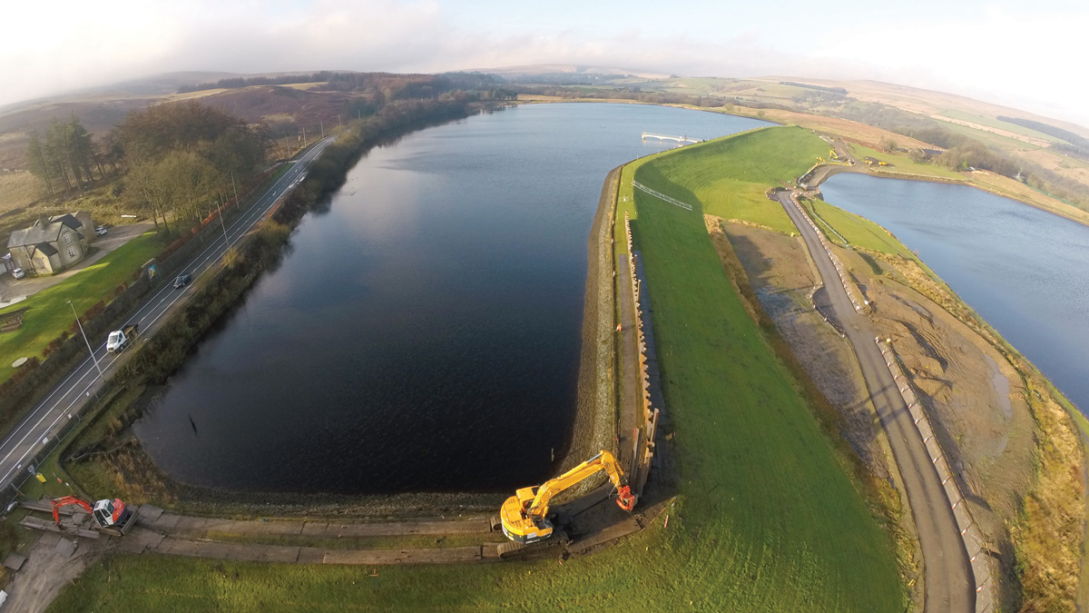
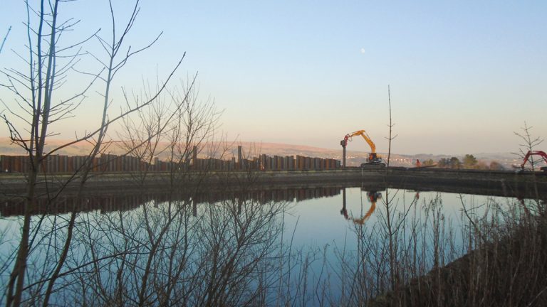
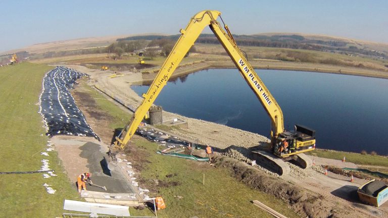
Installation of the crest sheet-pile cut off wall using a Movax vibrating hammer at Springs IR. Dingle IR is visible at the embankment toe - Courtesy of MMB
United Utilities (UU) is the statutory undertaker for 132 impounding reservoirs (IRs) retained by earth-fill embankment dams which fall under the requirements of the 1975 Reservoir Act. Before the era of ‘Pennine’ type clay core construction techniques, many impounding reservoirs that were constructed around the turn of the nineteenth century were substantially homogenous, comprising of materials that were abundantly available in the local vicinity, including a mixture of clays, gravels, sand and peat.
Springs Impounding Reservoir
Situated to the north-east of the A675 road between Bolton and Belmont, Springs IR was completed in 1830 and was one of the last dams constructed before the introduction of the ‘Pennine’ type dam. Historic drawings of the site suggested the existence of a clay core, but recent geotechnical investigations have shown no evidence of such. Dingle IR sits at the base of Spring’s embankment, which is submerged when Dingle is at its top water level.
Portfolio risk assessment
UU uses a Portfolio Risk Assessment (PRA) methodology, which is based on the University of New South Wales’ method of assessing the risk of failure of embankment dams. This enables ranking of their dams at a portfolio level, thus determining those which lie within the intolerable region. This is based on an assessment of seepage, stability, flooding impacts and seismic risk. When used in combination with UU’s seepage toolbox, erosion risks can be assessed from initiation through to potential failure, to provide ranking and quantification of 29 potential failure mechanisms – termed initiation mechanisms (IMs) – allowing a targeted approach to risk reduction.
Design and build specialists Mott MacDonald Bentley (MMB) were engaged by UU to address the potential risk of internal erosion at Springs IR via:
- Initiation of erosion in a poorly compacted or high permeability zone in the embankment (IM-14).
- Initiation of erosion in a poorly compacted or high permeability zone around a conduit (IM-18), i.e. the existing cast-iron scour main.
- Initiation of erosion in a poorly compacted or high permeability zone into a conduit (IM-19), i.e. the existing stone tunnel and cast-iron scour main, and construction of a debris barrier surrounding the overflow channel.
- An ‘In the Interest of Safety’ (ITIOS) scope item, made by the Inspecting Engineer during the last statutory inspection under Section 10 of the Reservoirs Act 1975.
Working collaboratively
UU and MMB worked collaboratively against a challenging time frame, budgetary constraints and safety concerns to develop a solution for Springs IR that included a partial sheet-pile cut off wall within the crest of the embankment in conjunction with a part-face filter blanket and sheet-pile embankment toe wall.
This approach greatly reduced the amount of filter material required (when compared to a full-face filter blanket), resulting in a significant cost saving for the client due to a reduction in material required to comply with the filter envelope, as well as a reduced placement duration associated with the smaller blanket area. This approach required stringent record keeping to satisfy the evidentiary requirements of the project and ensure the required overlap between the crest sheet-pile wall and the top of the part-face filter blanket.
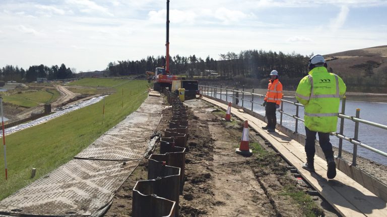
Piles installed short of design depth using a Movax vibrating hammer. This was overcome using an air hammer – Courtesy of MMB
Piling
PU18-1 steel sheet piles with a Waddit interlock sealant were chosen to provide a watertight barrier, adequate section modulus for driveability and sacrificial thickness to ensure a 100 year design life. The piles have been driven to depths of between approximately 6m and 8m below the probable maximum flood (PMF) level.
Due to the constraints of the site, different sheet-pile installation methods were investigated. Although initially favoured, silent-piling techniques were discounted due to access restrictions and difficult retrieval of plant from the embankment crest.
CPiles driven to design toe-depth using an air hammer – Courtesy of MMB
A Movax vibrating hammer (mounted on a 25T) excavator was selected. However, this method failed to achieve design depth (approximately 2m short of the required level). The likely reason for this resistance was the presence of cobbles/boulders or a stiffer layer of material. This was overcome using an air hammer. The combination of the two techniques greatly reduced the noise pollution from this operation.
As part of the solution (and to remove the need to run the filter blanket into Dingle Reservoir basin) a sheet pile wall was provided at the toe of Springs IR embankment. This approach removed the need for complex, deep excavations surrounding the existing tunnel and the associated safety risks. Throughout the works vibration monitoring was undertaken, as well as monitoring of any embankment and wave wall movement, ensuring that the works were not adversely affecting the stability of the embankment.
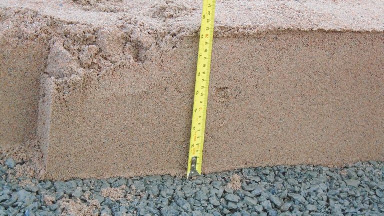
Filter material overlying drainage material (itself overlying filter material) within the part-face filter blanket. Formwork was used to ensure the correct layer thickness throughout – Courtesy of MMB
Filter blanket
The filter blanket itself comprised three layers of media: 250mm filter media, 250mm drainage media and 200mm filter media, all overlain with topsoil. The filter drains into an integral toe drain. A stringent inspection and testing programme was implemented on site to ensure that the filter material fitted with the design grading envelope, inclusive of on site grading checks.
To avoid material cross-contamination on site, discrete material storage bays were utilised. The use of temporary formwork in conjunction with levelling techniques ensured that the layer thicknesses were controlled. In addition, nuclear density testing was undertaken to ensure compaction was achieved per layer/bay.
A long reach excavator being used to place the part-face filter blanket. Use of this plant item vastly decreased the duration required for this operation – Courtesy of MMB
Slip-lining
The existing cast-iron scour main was slip-lined using 225mm diameter HDPE (SDR11) after extensive CCTV surveying and the removal of obstructions/deposits by robotic cutting. Due to the poor access (a 750mm ID cast-iron valve tower and similarly small inlet penstock) at the upstream end of the scour main, 6m lengths of HDPE were inserted from the downstream end using a 7T excavator.
Lengths were butt-fusion welded and then inserted once the necessary quality assurance checks had been undertaken. Once in place:
- The annulus between the host and product pipe was grouted using a high-flow grout.
- Breather pipework was placed at the soffit of the host pipe at its upstream and downstream ends.
- Further breather pipework was installed with small valves within the embankment tunnel.
- Grout was then injected from the downstream end at the invert of the host pipe.
Grout was witnessed at each of the breather pipe positions before finally flowing from the upstream end, confirming the annulus was completely full. On completion of the slip-lining operation, the tunnel was in-filled using a lightweight engineering fill.
Conclusion
Through collaboration, UU and MMB were able to develop a solution to meet both the technical and budgetary requirements of the project. Risks identified by using both PRA and seepage toolbox methods were addressed by the installation of both an embankment crest and embankment toe sheet-pile wall in conjunction with a part-face filter blanket and integral filtered toe drain.
On site challenges relating to the driveability of piles were overcome with the use of an air hammer following the initial installation of the piles with an excavator-mounted vibrating hammer attachment.
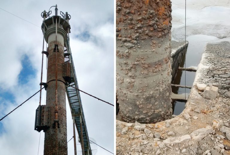
Due to poor access within the reservoir, a 750 mm ID cast-iron valve tower (left) with small inlet penstock situated between two stone wing-walls (right), the slip-lining operation was undertaken from the downstream end – Courtesy of MMB
Risks of potential loss of fines along or into existing conduits were mitigated by slip-lining the scour main and fully grouting the annulus between host and product pipes. The existing stone tunnel was in-filled using a lightweight engineering fill.
These works, in conjunction with accurate and detailed as-built site records, have reduced the probability of failure to within the ‘as low as reasonably practicable’ (ALARP) range, thus satisfying the requirements of the project.