
Swinstie Pipe Bridge Replacement (2018)
Site overview for new construction - Courtesy of aBV
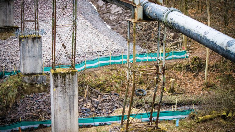
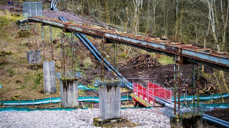
The existing Swinstie Pipe Bridge is located near Cleland, North Lanarkshire, and the structure supports a 450mm diameter iron gravity sewer pipe across the narrow, steep sided river valley of the Swinstie Burn towards Swinstie WwTW. The existing pipe bridge dates from the 1950s and has exhibited signs of severe distress for a number of years since significant movement of the ground started to occur. The partially wooded construction site area extends in a west/east direction and the Swinstie Burn bisects the site, flowing north/south. The depth of the valley is approximately 11.0m and the bridge spans approximately 70.0m being supported on seven concrete piers with lattice superstructure. Alliance partner aBV – a joint venture between Amey and Black & Veatch (now Binnies) is delivering Scottish Water’s SR15 Wastewater Infrastructure Programme, and was engaged to investigate, design and construct a complete replacement of the pipe bridge.
Background
Initial site inspections and desktop investigations were undertaken by CH2M in 2013 and 2014. These inspections documented the significant displacement of the piers particularly on the eastern side of the valley and indicated that the principal cause was landslip of the valley side. Their findings also confirmed significant buckling and lateral displacement of the pipe at the eastern end of the bridge although no leakage was noted. Initial remedial options focused on mitigation of the existing landslips, but stressed the requirement for a comprehensive ground investigation to enable a detailed evaluation of the cause and best remedial options to be developed.
Site investigation
The project was allocated to aBV to undertake site investigation works and geotechnical studies for a design and construction solution under the SR15 investment programme. The geotechnical exploration was undertaken by Socotec Ltd (formerly Environmental Scientifics Group (ESG) Ltd), during early 2016.
The geotechnical investigation comprised eighteen boreholes undertaken using initially dynamic sampling methods to investigate the superficial deposits with all boreholes then continued into the underlying sedimentary bedrock by rotary core drilling methods reaching a maximum depth of up to 43.30mbgl. Due to the topography and steep slopes of the site and the subsequent difficult access, much of this work had to be undertaken by specialist slope climbing rigs. As the site lay within an area of historic mining, the rotary boreholes were undertaken not just to consider potential foundation solutions but also to provide information on the mineral stability of the site within the underlying carboniferous coal measures.
To compliment the fieldworks, standpipes were installed in the boreholes, some including vibrating wire piezometers to allow not only monitoring of groundwater levels and the artesian groundwater conditions locally encountered but also to record the rate, depth and magnitude of any potential movement in the slope. Intensive laboratory testing both geotechnical and geochemical was undertaken following the fieldwork on the samples and core obtained.
Deformed pipe bridge tower – Courtesy of aBV
Ground model and failure mechanism
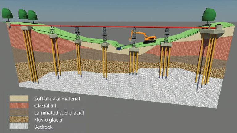
The results of the ground investigation confirmed that all instability was related to the superficial deposits. Although two principal coal seams were proven no voids or other evidence of old workings were encountered. A further separate detailed review of old mining plans, records and geological memoirs confirmed no risk of a more regional structural instability associated with fault and other planes of instability. A detailed cross section of the site is presented below which identifies two principal areas of very soft cohesive alluvial silty clays considered to associated with glacial withdrawal.
A layer of firm glacial till underlies the upper alluvial materials which in turn overlies a laminated fluvio lacustrine clay over a variable layer of fluvio glacial sands and gravels. These latter deposits are considered to be the product of sub glacial deposition during cyclic ice sheet advance and retreat. Research of geological archive maps in the Scottish library of the British Geological Survey confirmed the interpretation and highlighted numerous isolated but similar Quaternary depositional systems within the region.
Interpretation of the borehole inclinometers strongly indicated moderately deep slip zones at approximately 5.0m depth in the upper soft alluvial material. Digital slope analysis using specialist software was used to further refine the failure model and confirm that both the slope and associated foundation failures were a function of the inability of the soft alluvial deposits to sustain the applied loads and self- weight of the ground itself. The slope failures in particular would be further destabilised by increased pore water pressures following infiltration and surface runoff following heavy rainfall.
3D design model of pipe bridge and foundations – Courtesy of aBV
Options appraisal
The project team considered a number of options for remediation including the initial concepts of slope mitigation proposed by the client. However, following the detailed analysis it was considered that control of water both on the surface and within the slope were not sufficiently adequate and proposals focused on:
- Reconstruction using deep (piled) foundations.
- Replacement shallow foundations with an inclined anchor system (also considered by client).
- Stabilising the slope with a soil nailed system.
- Removing the structure and installing a pumped system.
The final design decision concentrated on the development of a deep piled foundation solution which would sustain the high lateral pressures from future slope movements without compromising the integrity of a new pipeline and associated superstructure.
Foundation design
Although piles are frequently required to withstand lateral pressures little previous work on piles in landslip areas has been documented. Those that are have largely been designed through empirical approaches and installed to limit collateral damage by arresting some or all of the slope movement. The piles themselves have largely been considered sacrificial as they did not support ancillary infrastructure.
In landslip areas the maximum lateral load transferred to a pile is a function of peak shear strength of the material at the time of failure, spacing of the piles and pile diameter. Work by Ito and Matsui (1975) developed an analytical method relating all the parameters and produced a series of charts demonstrating a logarithmic relationship between pile spacing, pile diameter and maximum load prior to plastic deformation (failure) occurring for given shear strengths.
Swinstie pipe bridge – Courtesy of aBV
Determination of the design loads was carried out from an application of Ito and Matsui’s work, cross checked with a more simplistic evaluation from the Mohr Coulomb failure criterion. On evaluation of the lateral loads a pile design was initiated using load displacement (p-y) analysis. A separate analysis was carried out using detailed Finite Element techniques to assess pile and pile cap deformation for varying trial pile diameters and types of pile.
Comparison of the various techniques was favourable and provided for a design of small pile groups for each new pier. Due to very high bending moments predicted from the p-y analysis the piles were designed as hollow steel circular section with a concrete infill to further resist buckling. Traditional rebar cages would be installed through the concrete to extend into the required rock socket in the coal measures strata.
To ensure that lateral loads on any pile group were limited, the pile caps and pile geometry were rotated from being in-line with the pipe direction to be square to the maximum slope. This would ensure that probable slope movement would be intercepted by at least two piles in line rather than on obliquely orientated piles which would increase the risk of pile group load.
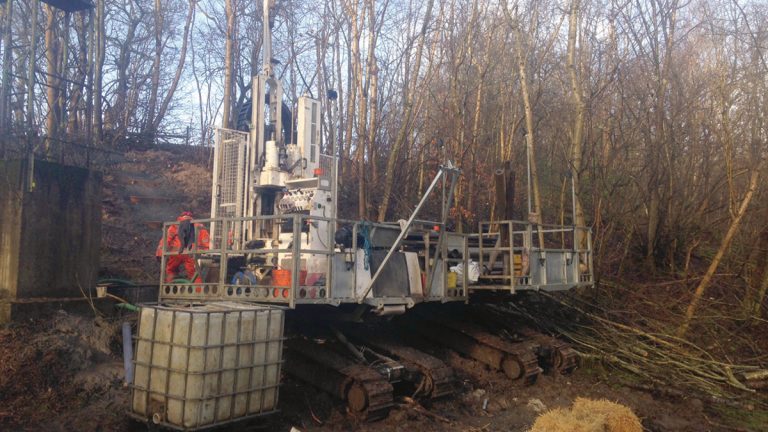
Slope climbing test rig for dynamic and rotary boring – Courtesy of aBV
Pipe design
The new pipe bridge will be an online replacement with the original structure and foundation supports being demolished. New foundations will be slightly offset from the original foundations avoiding the nearby watercourse. Support from the same number lattice modular tower sections which will carry the new standard length flanged ductile iron pipe incorporating Posiflex elastomeric expansion joint for to allow for longitudinal, lateral and rotational displacements due to thermal and mechanical movement accommodating minor residual pile deflections.
The design has been developed for ease of installation but also the most structurally suitable and economically viable solution which has drawn from the experiences on other similar projects.
Construction
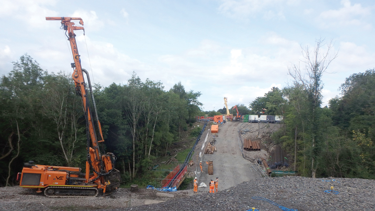
During construction over pumping will be required throughout as soon as demolition commences. Site preparation includes a road closure and a piling platform to be formed in order to overcome the challenging access constraints.
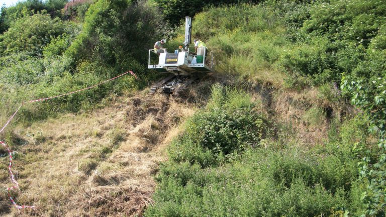
Rig in operation on slope – Courtesy of Geotechnical Engineering Ltd
Early discussions with the preferred piling contractor Van Elle led to changes in the initial piling design to incorporate a thicker CHS section up to 508mm instead of the original 457mm, due to better availability of both steel section and cutting shoes. By having a specially adapted rig ready for mobilisation, longer sections of CHS could be handled thus making a significant saving in section welding time.
Conclusion/update
At the time of writing (July 2018) site preparations for construction have been completed, off-site fabrication of the structural steel towers is underway and the piling operation has commenced and progressing well. Project completion is currently planned for January 2019.