
Tidal Energy Converter – Phase 2 (2015)
Studies have demonstrated that Great Britain has a globally significant tidal energy potential. Harnessing this natural resource and making tidal energy cost effective, and therefore attractive to investors, is now the marine energy industry’s primary challenge. The Tidal Energy Converter (TEC) project is run by the Energy Technologies Institute (ETI). Cost of energy (CoE) is a measure of the average cost, over the lifetime of a plant, to generate a unit of electricity. The aim of the TEC is to establish a long-term commercially viable CoE from tidal current technologies. In 2013, UK Water Projects included a case study titled Tidal Energy Converter System Demonstrator, which detailed Phase 1a of the project. Now the project has reached Phase two, designing and building a demonstrator.
TEC Phase 1
TEC Phase 1 was a collaboration between three partners. Atlantis Resources Corporation, lead contractor; Black & Veatch (now Binnies), project manager and technical advisor – primarily on the support structure and foundation aspects; Lockheed Martin, system integrator and technical advisor – primarily on electrical and mechanical aspects.
Assessing array performance, as opposed to that of individual tidal energy converters, is a very important element of TEC. Understanding this area is central to moving from demonstration to commercial scale systems. Commercial operators need technologies which function effectively at large array scales.
In its Marine Energy Technology Roadmap, published in conjunction with the UK Energy Research Centre in 2010 (and updated in 2014), the ETI recognised a critical objective for the marine industry is to achieve a CoE, for large-scale projects of c. 200MW scale, of within the 10-20p/kWh range from 2020.
This was seen as the level at which marine energy could successfully compete with other forms of generation for investment, and demonstrate an ability to reduce costs beyond 2020.
Following a review of competing tidal energy prototypes Phase 1a of the TEC arrived at a ‘preferred architecture’ for a generation system that should reach the ETI’s CoE target architecture (see Tidal Energy Converter article in UK Water Projects 2013). Phase 1b created an outline design of the optimal system based upon the preferred architecture.
TEC Phase 2
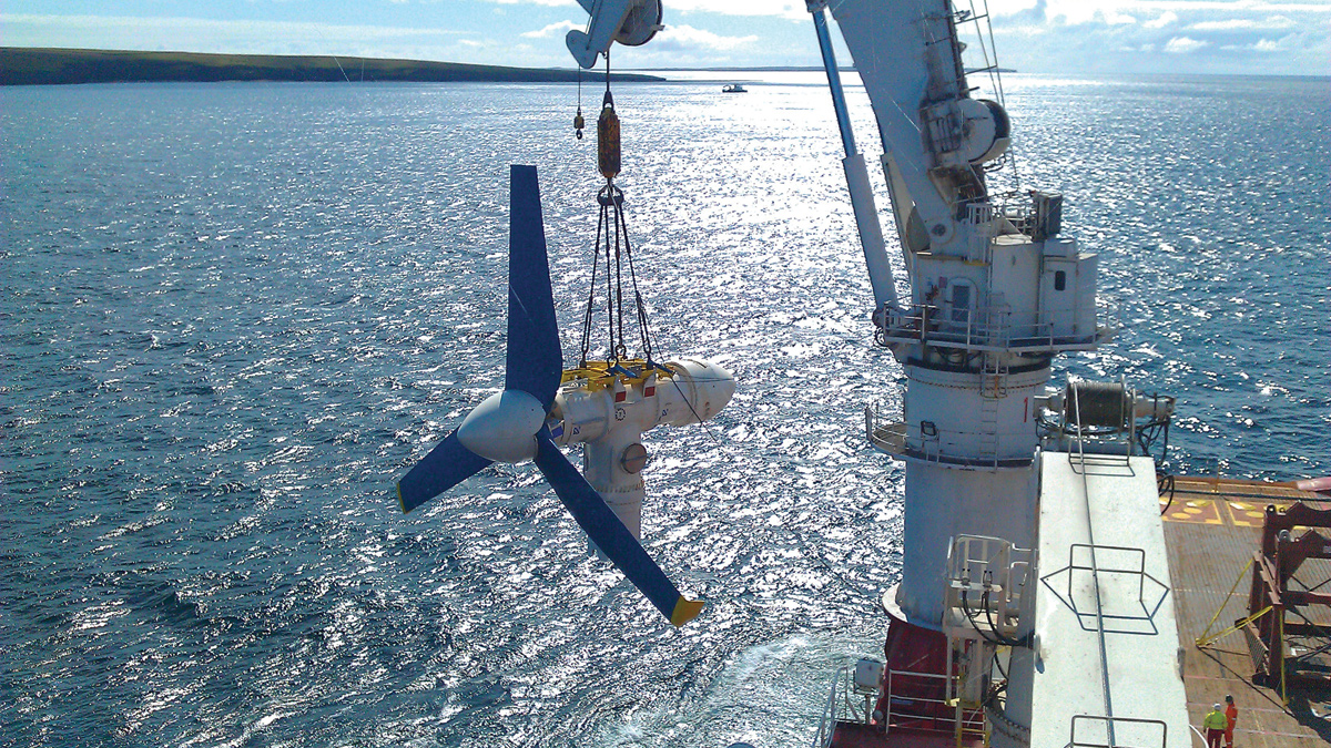
Phase 2 of the TEC, the focus of this article, aims to demonstrate the innovations identified in phase 1a and 1b which have the greatest impact on CoE: particularly the tidal turbine support structure (TSS) on which the turbines are mounted. Black & Veatch is the lead designer for the support structure and has, during phase 2, developed a robust design methodology using offshore standards supplemented with tank testing and computational fluid dynamics (CFD) studies to address uncertainties associated with the design of a new and innovative support structure.
Advances in support structure design which achieve CoE reductions often introduce aspects that cannot be modelled effectively using existing standards and numerical techniques alone. For example the application of Morison’s Equation, to calculate hydrodynamic loads on the TSS, may not be appropriate for more complex geometries. In such cases tank testing to validate numerical models in combinations of wave and current conditions is required.
In addition, the conditions in which vortex shedding from a structure occurs, and the frequency of shedding, are critical parameters for definition of the stiffness characteristics required of the structure to provide acceptable structural dynamics. Empirical data often exists in standards but may not apply directly to the structure in question. In this case dedicated tank tests using sophisticated laser doppler velocimetry (LDV) instrumentation was used to address this design uncertainty.
Non-dimensional scaling groups for waves, current and rotor behaviour are often mutually incompatible so careful experimental design is required and tank tests can also be effectively supported by numerical CFD studies; for example, to assess the impact of rotating rotors on the on-set of vortex shedding. Tank testing may also be utilised to reduce design uncertainties in installation phase loads such as slamming – impact loads due to waves breaking on a structure – which can have a significant impact on the design envelope.
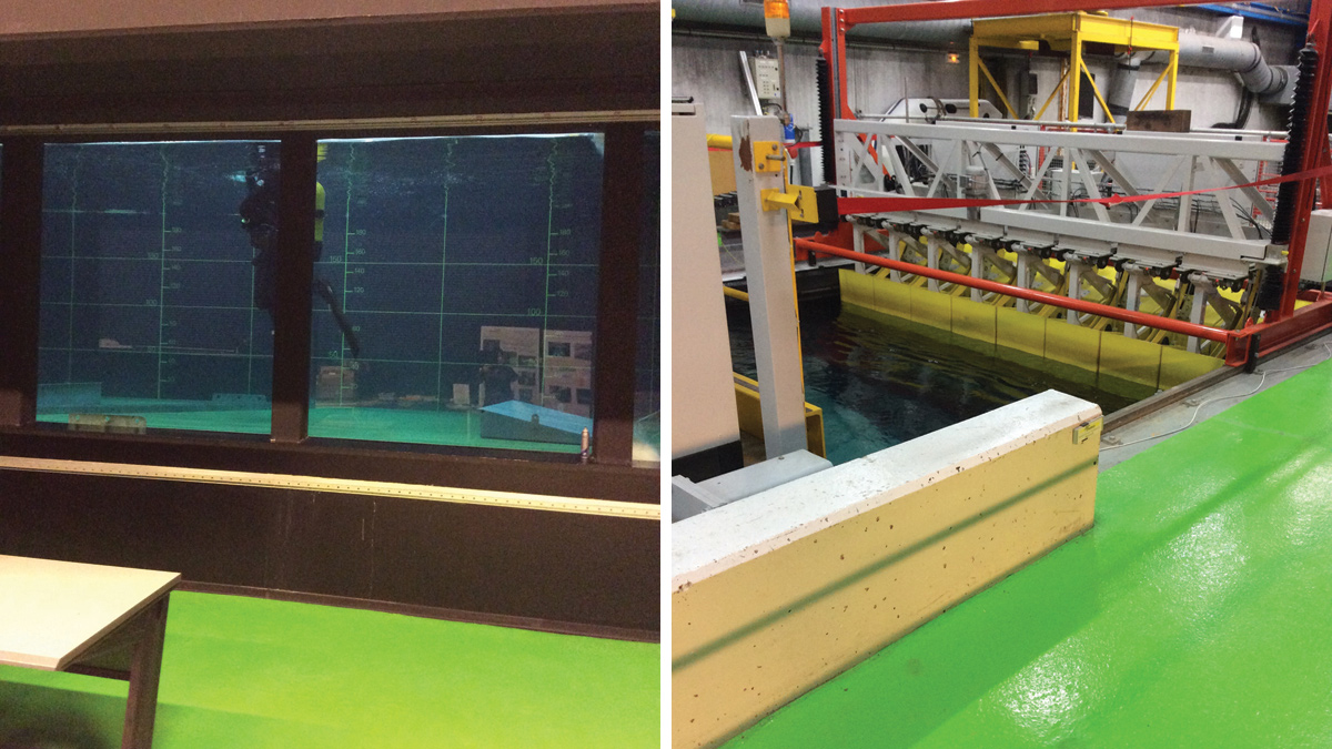
(left) IFREMER wave-circulation tank bottomside and (right) IFREMER wave-circulation tank topside – Courtesy of Black & Veatch
Analysis software
Analysis software used in the TEC Project uses Morison’s Equation to calculate hydrodynamic loads on the support structure as well as other stationary bodies such as the yaw drive and turbine nacelle units. Uncertainties in the application of Morison’s Equation form the basis for the scope of the series of hydrodynamic scale model tests to address each of these uncertainties.
Current flow past a structure may cause unsteady flow patterns due to vortex shedding. Should the natural frequency of the main structure members lie close to the vortex shedding frequency of the member, the vortex induced vibrations (VIV) can adversely affect ultimate limit state loads and fatigue life of the structure.
It is extremely difficult to quantify the forces exerted on the structure due to VIV in a tank testing setting as this would require accurate scaling of a multitude of aspects such as waves, currents, mass, velocity profile, turbulence, damping, roughness, etc. A more feasible approach was to determine the structure’s vortex shedding frequencies. This data can then be used to inform the design process by either avoiding a natural frequency of the structure which could elicit a lock on excitation response within the expected flows or in the assessment of such behaviour to demonstrate acceptability.
Detailed design phase
During the detailed design phase, consideration was also given to the temporary load cases which drive elements of the design during the installation and decommissioning phase of the project. The following detailed design activities were completed during this process:
- Preliminary lifting analysis of the structure to inform the development of a lifting plan and the initial specification/ design of a suitable rigging arrangement.
- Development of an installation methodology provided for the structure, including the definition of temporary load conditions (i.e. load cases and associated loads) that will be experienced during temporary phases (e.g. loading out, transit to site, lifting installation).
The temporary load cases for the structure during installation are of significant importance, particularly for wave impact loads, such as slamming loads, imposed on individual structural members when lowering through the splash zone. The concern is the transmission of the potential slamming loads and the resulting bending moment at the root of these members.
A further aspect of the installation phase is the stability of the structure as it is lowered through the water column to the seabed. The behaviour of the structure, in this free hanging configuration, is of interest as, prior to testing, it is unknown if the structure will tend to find an equilibrium position when suspended in the water column during wave and current conditions or whether it will tend to oscillate either laterally or rotationally about the main crane line.
To support this design work, a series of marine operations tests have been carried out to confirm this slamming coefficient as it applies to the structure under design as well as the stability characteristics of the structure as it is lowered through the water column in typical installation environmental conditions.
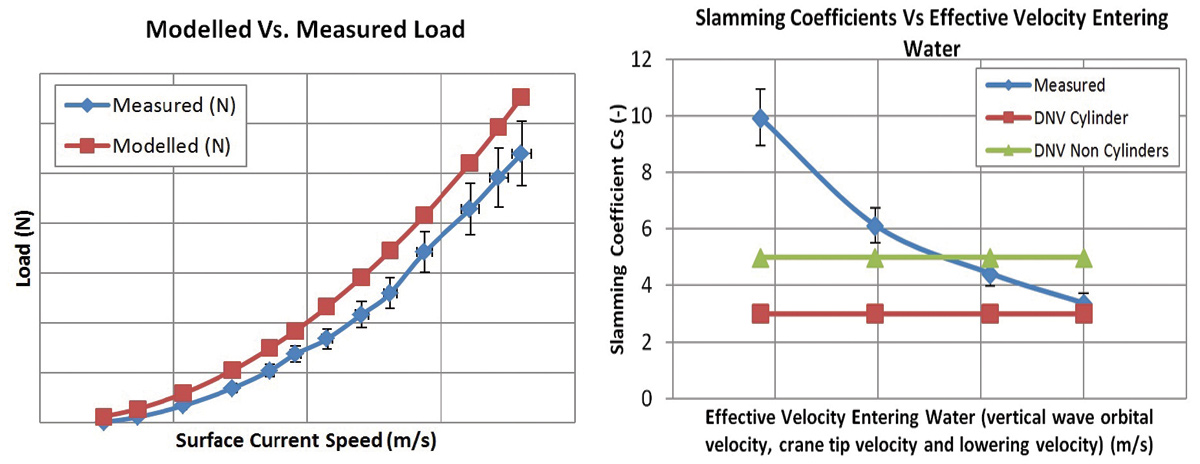
(left) Fig. 1 Measured load versus Morison’s Equation modelled load on a structural member of the TSS and (right) Fig. 2 Measured TSS structural member slamming coefficient relative to industry standard values – Courtesy of Black & Veatch
Scaled model tank testing
Following identification of the uncertainties covered above, it was decided to carry out scaled model tank testing. It was determined that the facility which offered the best combination of capabilities and total cost to suit the scope and budget was the IFREMER facility, Boulogne-sur-Mer, France. The following outlines the various considerations in the design of the tank testing campaign
The typical approach to estimating a suitable scale to adopt in model testing is to begin with the facility limitations themselves in terms of:
- Water depth.
- Tank area: model area ratio.
- Flow conditions.
- Wave conditions.
Based on the constraints imposed on these considerations by the IFREMER facility, a scale of 1:20 satisfied the following:
- Installation site water depth.
- Acceptable blockage to flow.
- Extreme flow conditions.
- Operational wave conditions.
- Operational combined wave-current conditions.
To correctly model the TSS at model scale, geometric, dynamic and kinematic similarity needs to be satisfied. In practice, this is not fully achievable due to the incompatibility of scaling both Reynolds and Froude numbers simultaneously using freshwater as the liquid.
This presents a challenge in that the most appropriate scaling law should be adopted based on the parameters to be measured during specific scaled environmental conditions.
For the tank testing of the model of a TSS, due to the requirement to model both waves and current, Froude scaling was used with artificial techniques then applied to give the correct flow regimes at lower Reynolds numbers, e.g. turbulence and surface roughness.
CFD simulations
The primary objective of the CFD simulations was to act as a flow visualisation tool and to assess the impact of rotating tidal turbine rotors on the onset of vortex shedding from the TSS. This required a number of geometrical configurations to be tested in a range of flows. Initially, the TSS was tested in isolation in a range of configurations and a sensitivity study carried out on the turbulence models to be used in the remainder of the simulations. No vortex shedding from the TSS in isolation was observed.
While this was encouraging, these fundamental behaviours of subsea structures should be validated. This was undertaken through the tank testing, which located vortex shedding for a particular TSS configuration.
The use of CFD has been treated as a guide only in qualitative assessment of the flow field around the TSS in isolation and TSS with rotating rotors. In Black & Veatch’s view these simulations could not have been used in isolation to inform the detailed design of the TSS without appropriate validation material through tank testing.
Conclusion drawn
On completion of the tank testing campaign, CFD simulations and analysis of the priority datasets, the following was concluded:
- The application of direct hydrodynamic loads to the TSS from waves and currents has been shown to be conservative when using industry standard drag and inertia coefficients and the Morison’s Equation formulation in the majority of cases, but some corrections have shown to be required in certain cases to provide conservative estimates of loadings.
- Vortex shedding was found to occur at a single TI value from the TSS and only in a temporary configuration of the TSS following installation. This data allows numerical calculations to be performed to either avoid coincident natural frequencies of the structure or demonstrate acceptable behaviour of the system in these cases.
- The installation tests have informed the design process in respect of the most appropriate configuration in which to install the TSS up to maximum installation limits. This testing has provided a valuable dataset from which the installation plan may be developed and de-risked significantly on the basis of the behaviour observed during this testing
- The slamming coefficient, Cs, determined from the dedicated tests for a particular TSS structural member align with industry recommended coefficient values for typical installation environmental limits for vessels and lifting operations. Therefore no further modification to this coefficient is necessary in the determination of final design loads.
The tank testing campaign and CFD simulations confirmed that the design methodology adopted by Black & Veatch to perform the detailed design of an innovative TSS, that will achieve CoE reductions, is suitably accurate and cost effective.
Summary
This work has addressed the variety of design uncertainties which existed in the application of direct hydrodynamic loads on the TSS, the behaviour of the TSS during lifting operations during installation and the appropriate slamming coefficient to use on the TSS structural members for temporary phases loads analysis during installation.
The value of this work cannot be understated in the context of achieving certification of the TSS from an independent body. Addressing the uncertainties in the design which existed from the outset has been crucial in achieving acceptance of the design methodology adopted and the resulting design of the TSS.