Tynywaun WTW (2018)
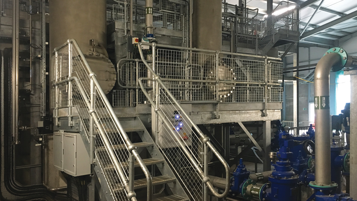
DAF recycle saturator system - Courtesy of Skanska
Tynywaun Water Treatment Works forms part of the South East Wales Conjunctive Use System (SEWCUS) chain of water treatment works that supply the central South Wales valleys and cities of Newport and Cardiff. This SEWCUS system does not, however, provide full conjunctive use to the Tynywaun distribution area, having very limited connectivity. The works has a current design capacity of 10 Ml/d; however, only 1 Ml/d can be re-zoned into SEWCUS, meaning that the current supply area is largely single source. The main criteria for the design was to upgrade the treatment process to enable the works design capacity to be maintained by overcoming the changes in raw water quality caused by deforestation in the catchment. This new stage of treatment will reduce the loading on the existing filters and enable the design plant throughput to be maintained.
Existing process
Tynywaun WTW currently comprises two stages of rapid gravity filtration. The existing processes are struggling to treat the deteriorating raw water quality and even during normal rainfall, discolouration of this water results in frequent shut-downs of this source.
With extreme weather conditions likely to persist in the future, then this will prove more challenging to the current treatment process which will ultimately result in a decrease in final water quality. In particular solids loading onto the existing filters is causing problems, flocculation is poor, and the control of coagulation pH is difficult. A number of water quality parameters have demonstrated a potential to contravene the regulatory requirements in terms of turbidity, total coliforms and cryptosporidium.
It was decided that an additional future redundancy provided by a 12 Ml/d DAF plant would be most beneficial and would enable the future growth plans for the Tynywaun network. However, in the short term, as the current works is designed to 10 Ml/day, the installation of a 12 ML/day DAF and refurbished first-stage filters capable of treating 12 Ml/day will still limit works capacity to 10 Ml/day (future investment will be required to increase the second stage filter capacity and transfer pumps to operate at the 12 Ml/d capacity).
Having to determine the relative size and positions of assets before planning restricted any efficiencies that may have been available. There was one area of flat ground on site which met the dimensional requirements. Trial holes were bored in the approximate four corners of the DAF building.
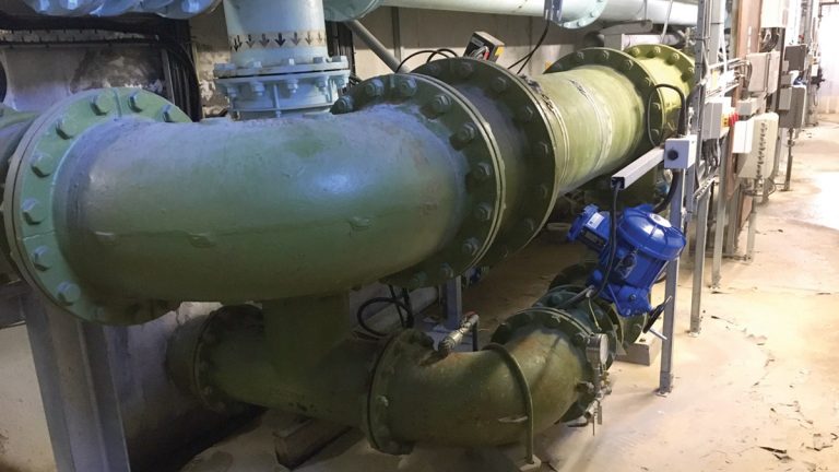
RGF filter pipework gallery before improvements – Courtesy of Skanska
Clarification process
To enable the works design capacity to be maintained by overcoming the changes in raw water quality caused by deforestation in the catchment a new clarification treatment stage is being added upstream of the existing filters. Flocculation and dissolved air flotation (DAF) treatment was the selected clarification process. This has been proven to be an effective treatment process for upland waters and has been selected for a large number of treatment works in Wales.
Restricted site
Access to the site is severely restricted, with the works being located in a steep series of roads at the end of residential terraced streets. Following consultation with local residents, it was agreed that a flat bed 20’ lorry would be the largest vehicle that could deliver goods to site. This placed a considerable restriction on the number of deliveries that could be made to site and what equipment could be brought to site by those deliveries.
Constructing the DAF slab and structure
The topography of the site also restricted the design possibilities, with very little level land available on the site. This dictated the position of a new DAF plant and the preferred construction route of all pipelines. The DAF slab was to be constructed on top of 88 (No.) 600mm diameter concrete piles. Piling activities were hindered as substantial brick walls and concrete pads were discovered to be buried beneath the site and had to be removed. Between the piles below the slab a gas collection system was installed, and a gas membrane system has been connected and tested.
The three-lane DAF was built up from the slab as a traditional formwork reinforced concrete structure. The use of precast panels for constructing the tanks was considered, but deemed impracticable due to the site access constrictions and the limited area on site for material storage. Flocculation tank weir walls were constructed from precast rectangular sections which were craned into position and held in place by simple stainless steel bracketry.
The DAF slab would support a simple double span structural steel frame with raised roof sections to house the lime storage silo. A concrete precast wall was designed with panels that were specification sized around the delivery constraints. The precast panels were constructed with all apertures and heating, ventilation and air conditioining (HVAC) requirements built in. These precast panels, for security rating reasons, were 3m tall. The remainder of the wall and roof were constructed in insulated corrugated steel sheets to match architectural features on the existing buildings at the works. A ‘tensioned access platform’ was installed on the top of the building frame to provide fall protection whilst the roof was fixed. This provided both a working platform and fall protection and allowed for a very quick roof installation.
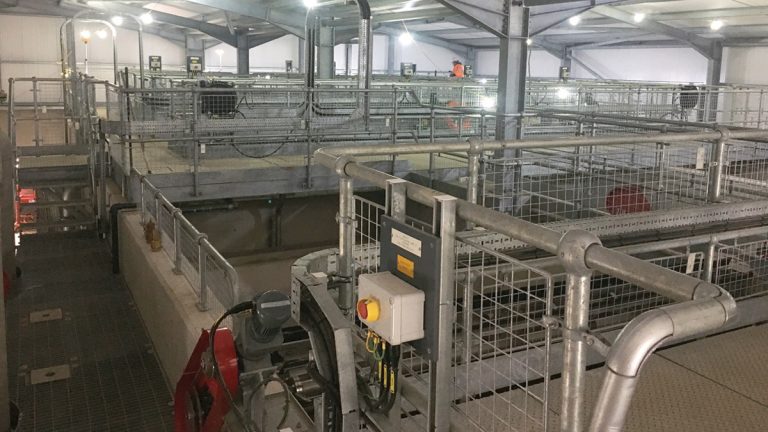
DAF during commissioning nearing completion – Courtesy of Skanska
To reduce the site assembly time, the DAF steelwork flooring was designed in welded deliverable sections complete with hand railing. These were craned into position on the DAF walls and bolted together. This saved assembly time and as fall protection was already available providing safe access for installation activities.
On-site wastewater management restrictions required the DAF de-sludge by the use of a rotating brush screen and beach weir. The sludge drainage was by gravity to the existing lagoons which have been improved with the provision of mixing pumps.
Tynywaun WTW – Table of designers, contractors and suppliers
- Design partner: Arcadis
- Principal contractor: Skanska Utilities
- Civil sub-contractor: Lewis Civil Engineering – now (Dec 2022) Envolve Infrastructure
- Mechanical installation sub-contractor: Industrial Pipework Services
- Electrical installation sub-contractor: Celtic Process Control
- System integrator sub-contractor: Cougar Automation
- MCC: GPS
- Lime dosing: Don Valley Engineering
- Chlorine & ortho dosing: Chemidose
- DAF skimmers: AJ Fabtech
- Alum dosing: Coloide Engineering
- Pressure vessels: Vessco
- Static mixer: NOV Chemineer
- Mixers: Lightening Mixers
- Standby generator: Edina
- Supernatant return pumps: Hidrostal Pumps
- Recycle pumps: Xylem Water Solutions – Flygt Pumps
- HVAC: ATC
- Auto and manual filters: Bollfilter UK Ltd
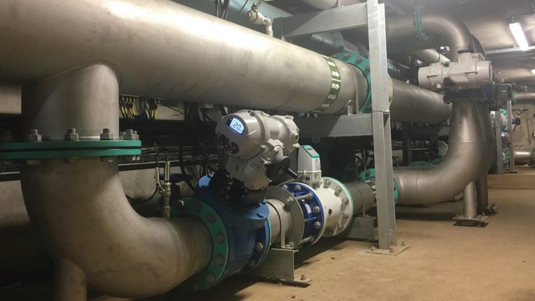
Rapid gravity filters (RGF)
The existing RGF first stage filters have also been improved with better flow control and additional rinse pipework. This required a significant amount of the existing flanged ductile iron pipework in the filter gallery to be replaced to allow for the installation of new flow meters and new connections for the rinse water pipework. Several major challenges needed to be overcome including:
- Very limited space in the filter gallery.
- The fact that only one filter at a time was permitted to be out of service for an extended period of time.
- Total plant shutdowns were limited to an 8- hour period.
This required a significant level of planning and a design that would enable the common filtered water main to be available and in service with a minimum of 8-hour plant shutdowns. The new pipework installed in the filter gallery was thin walled stainless steel which made installation easier as it is lighter than ductile iron.
The rinse water system allows the initial flow through a filter (after washing) to be diverted to waste for a period of time before the filter is returned to service. This ensures the water meets the required water quality standards. The rinse water is returned to the raw water reservoir by an integrated rinse return and run to waste pumping station.
A run-to-waste facility has also been incorporated into the works enabling the outlet from the first stage filters to be diverted to the rinse water lagoon should the filtered water quality be outside the filtered water quality envelope. This allows the DAF and first stage filters to be flushed out and returned to service more quickly. Water from the run to waste is then returned to the raw water reservoir.
Due to the complexities of the site, including the topography, traditional ductile pipework was used for connection of the DAF between the raw water reservoir and the first stage RGF. Tees were ‘cut into’ the existing pipework and valves and blanks fitted early on in the scheme. The newly installed DAF feed pipework would also contain dosing points for lime and aluminium sulphate.
RGF filter pipework gallery after improvements – Courtesy of Skanska
Chemical dosing systems
New lime and aluminium sulphate chemical dosing systems, storage and delivery systems were to be built in to the DAF building design. It was decided, due to the restricted area available to bury the DAF feed pipework, to build dosing chambers at the dose points complete with static mixers. The chambers were constructed very quickly using a cast plastic system which clipped together. Sections were assembled in layers and pinned together.
Service water system
A new service water system was installed to provide a supply of service water to the service water break tank. The existing system took a feed from the flow into the service reservoir. This meant that if the works was offline the service water break tank could not be refilled. The new service water pumps are fed from the outlet of the service reservoir, with a new pipeline up to the service water break tank. This ensures a supply of service water during start-up of the treatment works.
Stormcell tank
Planning approval conditions required the design of a no-detriment rainwater management requiring the construction of a 80m3 attenuation tank. Various options of tank construction were considered for the restricted site and programme. The team opted for a low-tech plastic ‘Stormcell tank’ solution constructed with connecting plastic crates wrapped in a plastic sheet. The tank was able to be constructed in a matter of days and back filled to allow the space to be utilised for storage.
Timescale
At the time of writing (June 2018) construction has entered the commissioning phase, the DAF is online in automatic control, with ongoing commissioning of the new chemical dosing systems due for completion in January 2019.