Upper Neuadd Dam Stability (2016)
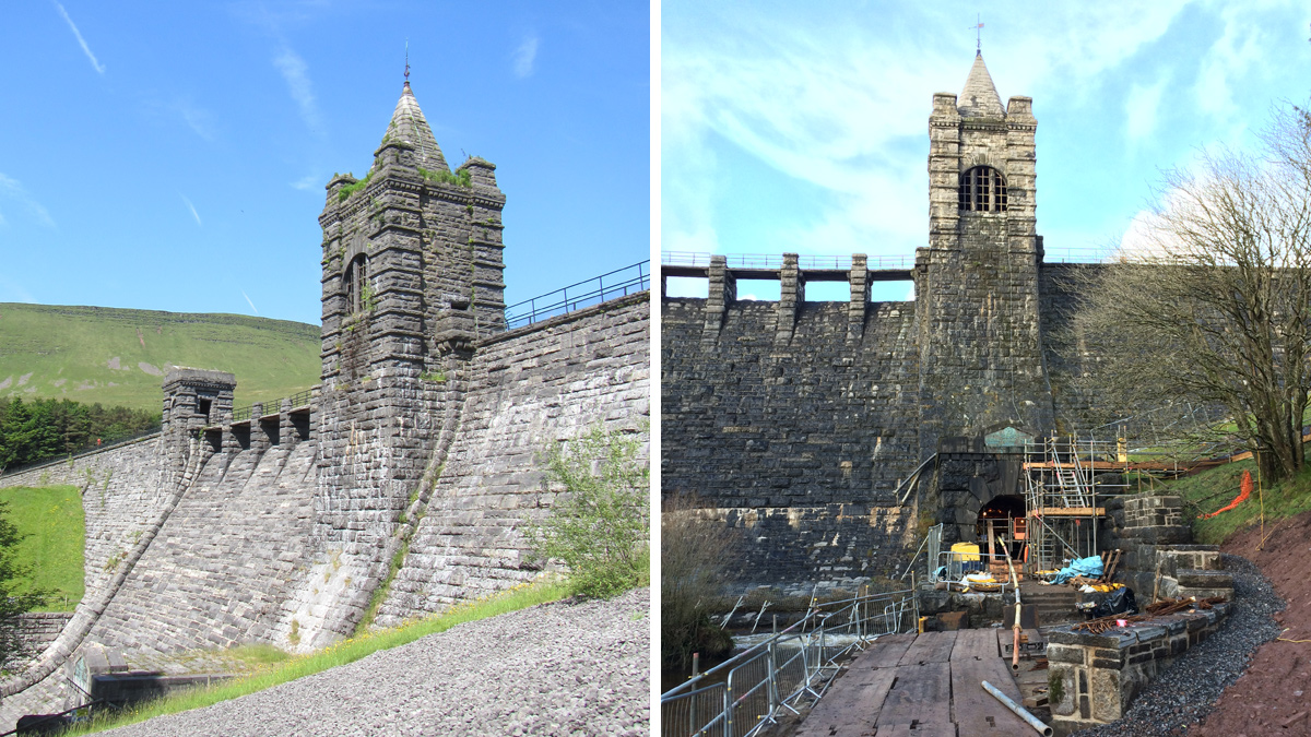
(left) Downstream side masonry work and entrance to tunnel and (right) tunnel lining formwork - Courtesy of Arup
Upper Neuadd Dam is a Grade II* listed structure, situated in the heart of the Brecon Beacons below Pen y Fan in the Taf Fechan valley, about 13km north of Merthyr Tydfil. It is owned and operated by Dŵr Cymru Welsh Water and is the upper dam in a cascade including Lower Neuadd and Pontsticill Reservoirs that feed Pontsticill Water Treatment Works, which in turn provides potable water for the Merthyr Tydfil area and down to the city of Cardiff. The dam is formed from cyclopean concrete clad in massive stone masonry, with flanking sections either side of the central overflow, supported by large earth embankments on their downstream faces.
Background and history
Upper Neuadd Dam was constructed between 1896 and 1902. It has a history of leakage, and various works have been carried out over the years to reduce this and to ensure the safety of the dam. These have included repointing of the upstream face and grouting of the body of the dam (1960s), and installation of stone drainage blankets in 1983. Further repointing works were carried out in 1990.
The dam was Grade II* listed in July 2005 ‘for its special interest as an architecturally-designed dam of spectacularly massive construction and definite character’.
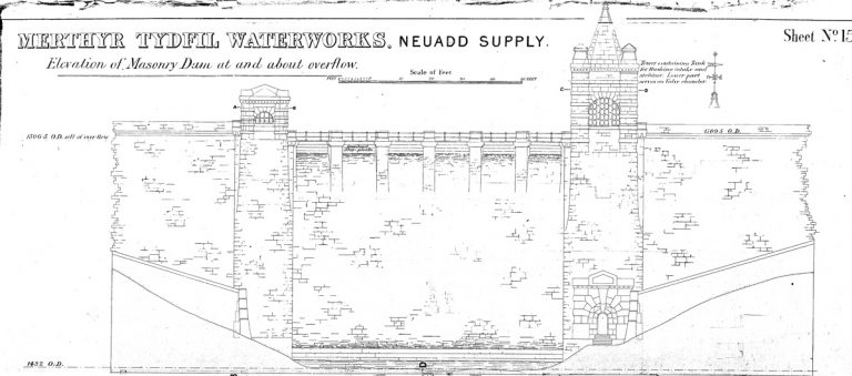
Elevation of spillway section – Courtesy of DCWW
In 2002, vertical extension of the scour outlet pipework provided a lower level bellmouth overflow. This reduced the reservoir top water level to approximately 6m below the original spillway overflow level under normal conditions. However, the catchment is typically steep, mountainous moorland, so the reservoir can fill rapidly, such that the lowered reservoir level could be exceeded, and therefore Welsh Water decided further remedial action was required.
A Section 10 Inspection was carried out in January 2013 by an All Reservoirs Panel Engineer in accordance with the Reservoirs Act 1975, and this led to the following recommendations of measures to be taken in the interests of safety under Section 10(6) of the Act:
- Either: Measures to limit the loading on the dam, by preventing the flood level in the reservoir during the passage of a PMF (probable maximum flood) rising above a level that is 1m below the present spillway crest.
- Or: Measures to ensure the long-term stability of the entire dam when the reservoir is filled either to the present spillway crest level (or to a slightly lowered spillway crest level) including during the passage of the PMF.
Dam construction details
The dam effectively comprises of three sections. The central section is a conventional masonry faced gravity dam with a hearting of masonry and concrete. The flanking sections on either side of the valley are of narrower sections, relying on the earth embankments downstream for stability.
Immediately adjacent to the central section there are transition sections where the footprint of the dam rapidly reduces from about 14m to 4.7m in width. The supporting downstream earth embankments have broad crests some 6m below the crest of the concrete dam.
Intrusive site investigation in 2013-14 confirmed that at many locations along the length of the dam the cyclopean concrete core was no longer intact. Various samples were recovered as rounded concrete fragments, eroded through long-term seepage.
The base of the cut-off was confirmed to lie approximately at the same level as shown on the 19th Century construction drawings, which provided some confidence that the dam was constructed as per these drawings.
However, the exploratory excavations against the upstream face of the dam confirmed the presence of substantial timber formwork, used to support the trenches during construction. This had degraded over time, and it was considered likely that the formwork struts could have been left in place, potentially providing seepage paths through the dam.
Standpipe piezometers were installed downstream of the dam, to supplement those already in place. Together, these confirmed that relatively high piezometric uplift pressures were being experienced in the formation soils downstream of the dam, particularly in response to increases in reservoir level.
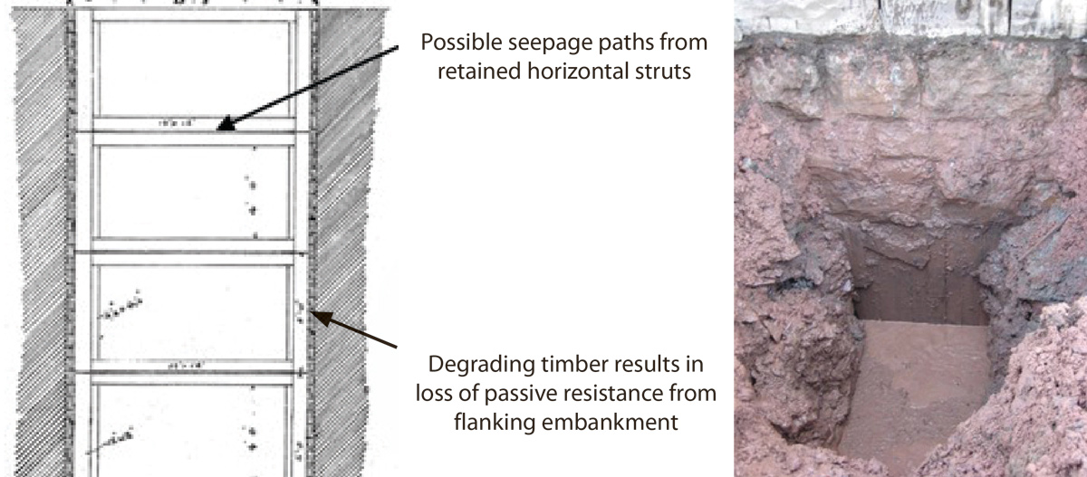
Evidence of timber formwork in trial pit, related back to record drawings – Courtesy of DCWW
Performance of the dam
Critical sections were identified for assessment of the dam’s stability, and analysis confirmed that although the non-overflow flanking section was stable against sliding, it was found inadequate against overturning, with a factor of safety less than unity.
However, in January 2014 a storm event occurred which caused the reservoir to fill and overflow the spillway. This suggested that the structure was stable under the loading applied during that event, although not necessarily with an adequate factor of safety.
Consideration of this event led the team to investigate other factors also contributing to the stability of the flanking section.
During the January 2014 storm event, significant leakage was noted, and evidence suggested that the dam had indeed deflected downstream and into the earth embankments. The conclusion was that repeated deflections during storm events over many years had exceeded the tensile capacity of the upstream face, which had resulted in cracks forming and water entering the hearting of the dam. Over time, the internal structure had deteriorated and preferential flow paths through the structure had formed.
This mechanism tied up with the site investigation findings of voids within the hearting and evidence of rounded aggregates.
Summary of analysis
Considering both the performance during the 2014 event and the findings of the site investigation, it was concluded that the stability of the dam could not be relied upon at higher water levels. The rotten timbers between the concrete and earth structures meant that the dam was not performing as a composite structure and the lack of passive resistance available from the earth embankment was resulting in excessive movement of the dam. Over time this had allowed cracks to form.
A short-term solution was agreed, to open the lowest valve on the scour main to maintain the reservoir at a significantly lowered level, whilst a longer term solution was developed. An enhanced inspection regime was implemented, and trigger level response procedures established in the event of the reservoir over-filling.
Developing a long term solution
Following a review of water resource availability, Welsh Water concluded that although the reservoir is not currently required for water supply, it is considered likely that the asset will be required in the future as the effects of climate change and increased demand take effect. Therefore, permanent discontinuance of the dam was not a preferred solution.
Further grouting works and installation of upstream membranes did not offer a long-term solution, due to the extent of the leakage issues and concerns over stability at higher water levels. The design team therefore considered options to ensure stability of the dam whilst managing leakage, including:
- Construction of a reinforced concrete wall on the upstream face of the dam.
- Vertical anchors with an upstream liner, or with grouting of the dam.
- Downstream buttresses built from the original dam foundation level with an upstream liner.
- Lowering the top water level by cutting new openings beneath the spillway; lowering the spillway section; constructing an auxiliary weir through the flanking embankment; or removing the plug in the outlet tunnel.
Optioneering and outline design
One obvious solution to maintaining a lower water level is to reduce the overflow level. However, as the dam is a Grade II* listed structure significant modifications to the overflow, which would change the appearance of the dam, were not favoured by the local planning authority.
Works required to strengthen the dam and enable the original top water level to be reinstated were very significant, and the costs were too high for Welsh Water to justify, particularly as the storage volume of the reservoir is not required in the immediate future.
The preferred solution that was adopted was to drain the reservoir using the outlet tunnel through the dam. This tunnel contains the scour and supply pipework and would have originally been used for river diversion during construction. Historic records indicated that the tunnel was plugged at impoundment with a 12-13 feet thick plug faced with engineering brickwork.
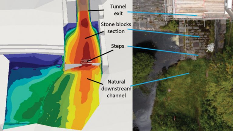
Variation of the maximum flow velocity above the downstream channel bed – 150 year event – Courtesy of Arup
The tunnel is 3m in diameter, and hydraulic modelling demonstrated that if the plug was removed, the tunnel would have sufficient capacity to pass the PMF event with water levels in the reservoir not rising above the safe levels determined from the stability analysis.
By carrying out works near the base of the dam, the appearance of the dam is not significantly affected and this option was therefore favoured by the local planning authority. The works are also reversible should Welsh Water wish to reinstate the dam to its original operational top water level in future years.
Detailed design
A computational fluid dynamics (CFD) analysis was carried out to assess the flow conditions within the proposed outlet tunnel and downstream channel during the PMF and 150 year return period flood events, and the main findings were:
- During a PMF event negative pressures would be developed in the tunnel with peak values of -80kPa at the tunnel entrance.
- The flow rate through the tunnel is predicted to be 64m3/s during a PMF event with a maximum velocity of 16.5m/s.
- Under the 150 year return period flood, the maximum velocities in the downstream channel are of the order of 14m/s.
There was therefore some concern regarding the potential for negative pressures to ‘pluck out’ the masonry immediately above the tunnel inlet and the ability of the existing brickwork that lined the tunnel to withstand the negative pressures and high velocities predicted.
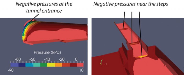
Negative pressure zones in the proposed tunnel – PMF event – Courtesy of Arup
To mitigate these, a 150mm thick reinforced concrete lining to the tunnel was designed to improve the hydraulic performance and resist the negative pressures at the entrance and across the internal steps. Furthermore, the upstream entrance was also to be protected by a stainless steel liner (‘top hat’) that was tied into the concrete lining. This overlaps the stone masonry and brickwork on the upstream face of the dam.
A further consideration was the risk of scour to the masonry apron and grassed riverbank downstream from the tunnel outlet. The existing masonry apron was of similar construction to the dam spillway and this was extended and a curved deflector wall designed to provide erosion protection and to deflect flows into the existing stilling basin.
Construction
Construction works commenced in September 2015 following an extended planning/listed building consent determination process. The works on the downstream side of the dam comprising the new masonry apron, curved defector wall and tunnel lining, progressed well as these works could largely be completed independent of water levels in the upstream reservoir basin. The 150mm thick reinforced concrete tunnel lining was achieved using curved steel formwork panels bolted together to fit the required profile of the tunnel, and pumped concrete was compacted using bolt on external shutter vibrators.
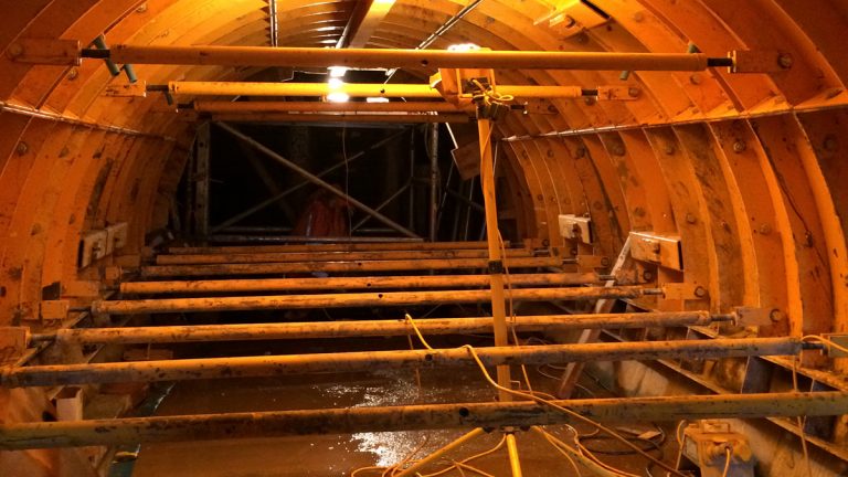
Tunnel lining formwork – Courtesy of Arup
The works on the upstream face of the dam, which included removal of the engineering brickwork plug, installation of the stainless steel insert (‘top hat’) and installation of a trash screen, were heavily constrained by the water level in the reservoir basin. The existing 450mm diameter scour main was kept open throughout the construction works, but it had insufficient capacity to prevent the reservoir basin partially filling during the numerous storm events experienced throughout the winter of 2015/2016.
A favourable weather window was finally achieved in February 2016, which allowed works on the upstream face of the dam to commence. Construction works were completed in April 2016.
Conclusion
Upper Neuadd is a Grade II* listed dam in the heart of the Brecon Beacons. Detailed investigations, studies and analyses undertaken on the dam structure have enabled the team to understand the dam’s performance in operation and explain the observed stability and leakage problems.
Following a review of options to abandon, rehabilitate or discontinue the asset, a solution was found that ensures the long-term stability of the dam whilst retaining the appearance of the listed structure. It will also enable Welsh Water to fully rehabilitate the dam to restore the original full operational top water level for the reservoir if required in the future.