
Medlock Quality Programme (2019)
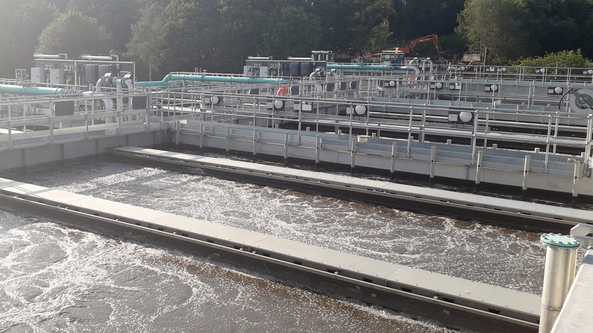
Failsworth WwTW - Nereda® plant operational - Courtesy of Laing O’Rourke
Medlock Quality Programme is part of United Utilities AMP6 investment programme across the North West and is the third Nereda® Reactor Plant to be operated by United Utilities. The scheme can be split into two distinct areas: (i) the upgrade of Failsworth WwTW to meet the new discharge consent and reduce the volumes of spills from the combined sewage overflow (CSO) and storm tank and (ii) a cluster of storm storage solutions across the Oldham combined sewage network to reduce discharges to the River Medlock. The main drivers are compliance with the Water Framework Directive (WFD) water quality standards in the River Medlock and compliance with the new 2mg/l ammonia and 2mg/l phosphorus final effluent standard at Failsworth WwTW.
Solution summary
The scheme, designed and delivered by LiMA (Laing O’Rourke Atkins), combines the separate outputs into a ‘batched’ programme, providing an innovative approach, resulting in an efficient holistic solution that addresses the improvement required over the catchment. Project delivery has been achieved successfully in a short time scale by employing collaborative working practices, BIM integration, and best for project decision making.
This case study details the major works that were required at Failsworth WwTW, Hathershaw Playing Fields, Bardsley Pumping Station and downstream of Snipe Clough CSO to meet the Medlock Quality Programme needs.
Failsworth WwTW: Project summary
The existing treatment plant is located 6km to the north-east of Manchester, serving the town of Failsworth and the surrounding area. The site is on the bank of the River Medlock, with both storm overflow and the treated effluent discharging into the river.
To meet the tightened consents at Failsworth, all treatment processes (except pre-treatment) are being replaced by a new Nereda® treatment plant which removes both ammonia and phosphorus from the influent flow allowing a tightened consent to be met in a smaller footprint than other conventional technologies.
To meet the increase in river quality additional 10,000m3 flexible storm storage has been constructed. In addition, an opportunity arose to increase the FtFT flow, resulting in less flow to the storm tanks and ultimately to the river. Significant costs savings will be generated through reducing storm storage.
The following civil structures and mechanical plant where constructed and installed at Failsworth WwTW:
- Nereda® cells 15m x 25.6m x 8.4m high (7.8m process depth).
- 2 (No.) Nereda® sludge buffer tank (6m diameter glass coated steel tank).
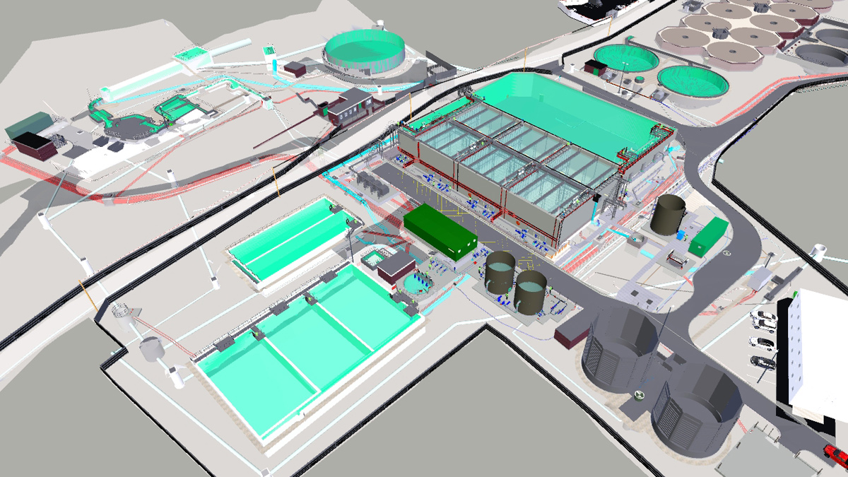
Extract from digital model showing new Nereda® plant – Courtesy of Laing O’Rourke
The following civil structures and mechanical plant where constructed and installed at Failsworth WwTW:
- Nereda® cells 15m x 25.6m x 8.4m high (7.8m process depth).
- 2 (No.) Nereda® sludge buffer tank (6m diameter glass coated steel tank).
- 1 (No.) SAS buffer tank (6m diameter glass coated steel tank)
- Nereda® buffer and pumping station (5m x 25.6m x 7.8m high).
- 4 (No.) blowers and blower slab.
- Nereda® MCC kiosk.
- New laboratory and SCADA room.
- New storm return pumping station.
- New LV kiosk and ducting.
- New sludge MCC kiosk.
- Sludge thickeners and polymer dosing rig.
Failsworth WwTW: Challenges and success factors
The original solution for the treatment works required the installation of tertiary filters to help remove phosphorus and solids post Nereda®. However, during detailed design it was determined that the Nereda® plant could meet the tightened discharge consent on its own, therefore the decision was made to remove tertiary treatment, resulting in a significant cost saving.
During the process design of the Nereda® plant, an opportunity was identified to omit ferric dosing, as the Nereda® process can achieve the new discharge consent without addition of ferric.
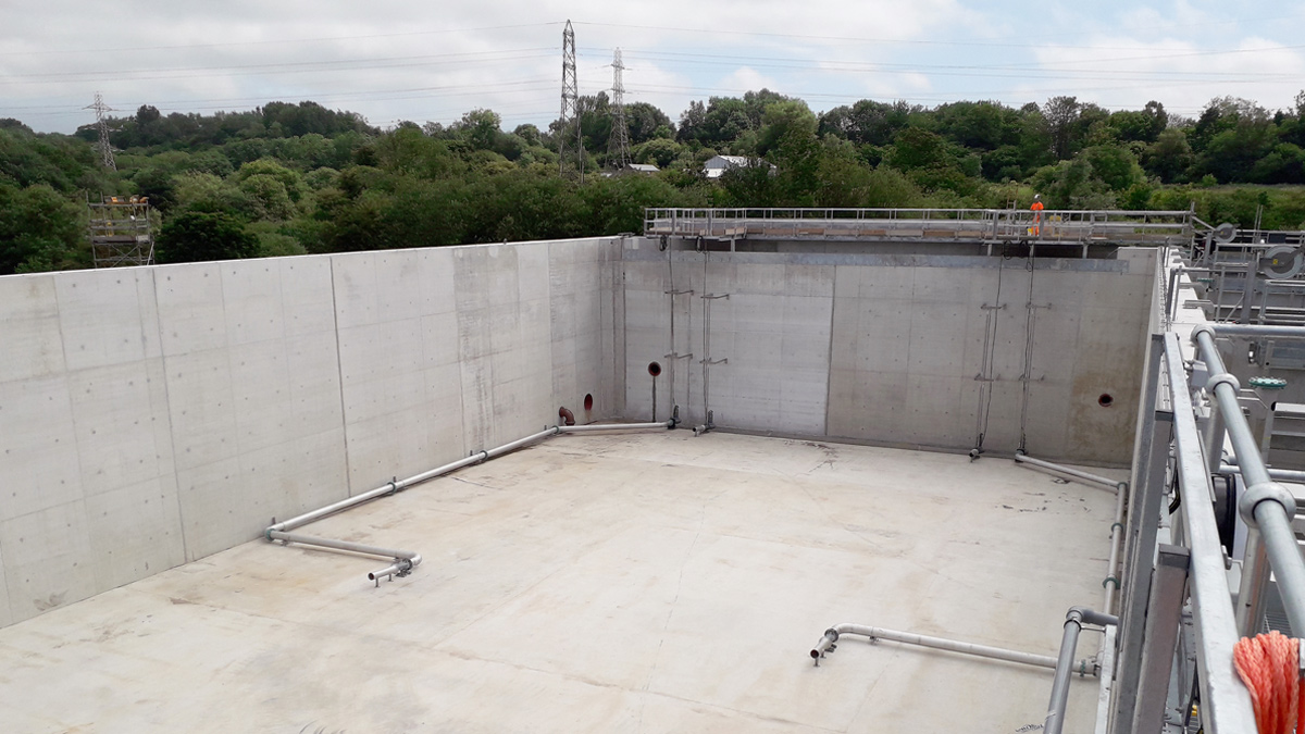
Failsworth WwTW – New 10,000m3 storm tank – Courtesy of Laing O’Rourke
On-site free space at Failsworth was limited. All UU owned land had been developed previously and the site was surrounded by the river and other industrial units. This represented a significant construction challenge, as the only land available for the Nereda® was on the land occupied by a disused sludge press house. Very little space was available for site facilities and materials storage.
To meet the water quality improvement required, an additional storm tank was needed to reduce the spills to river however, this tank needed to be flexible and receive flows from the existing storm tank and CSO overflow. To meet the consent, no flow could discharge to the river before all tanks where full on site. To achieve this a series of additional pipelines and actuated valves where installed to allow flows to be pumped into the tank and gravity return to a storm return pumping station.
Due to the space restrictions on site, the storm tank was combined with the Nereda® tank, allowing the two tanks to share a common wall. This generated a cost saving and allowed a more compact solution to be developed.
DfMA was used where possible on site. The main DfMA assets were the kiosks, including MCCs, switchgear, laboratory, SCADA room and poly-dosing kiosks. These kiosks where designed in such a way that they could be delivered to site fully fitted out and placed directly onto the civils foundation structures.
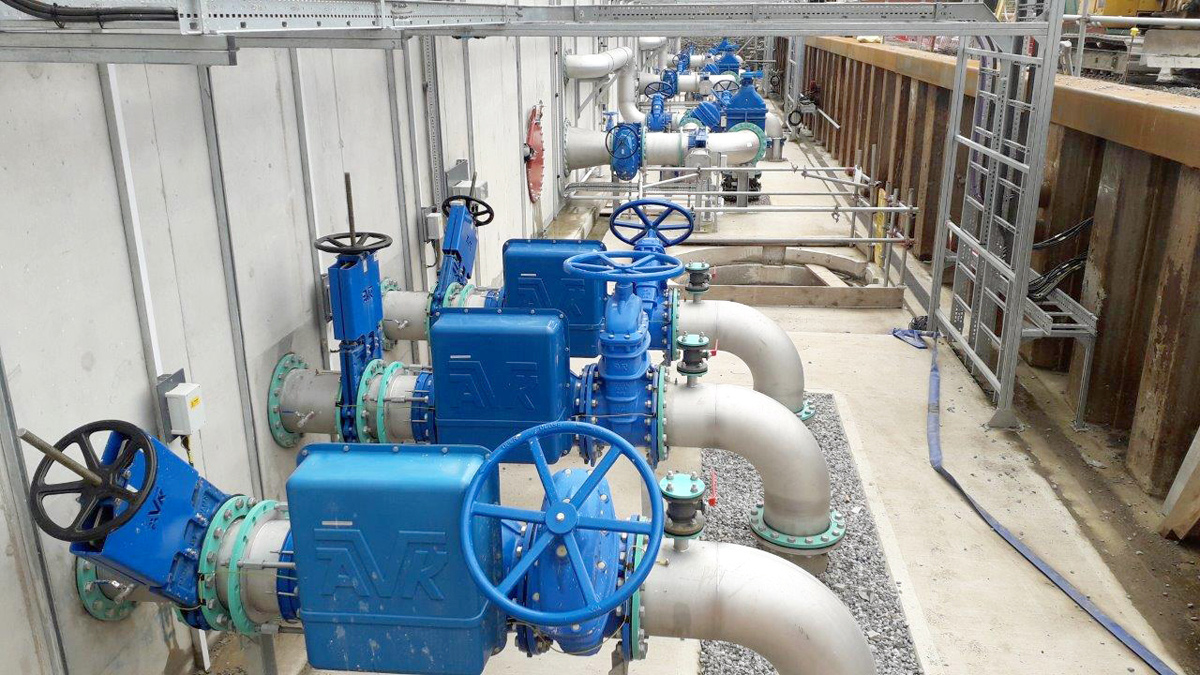
Nereda® influent, water level correction and desludging pipework – Courtesy of Laing O’Rourke
Hathershaw Playing Fields (5400m3 storage): Project summary
Located in a college playing field, in Oldham, the detention tank was constructed adjacent to an existing CSO. Construction involved connecting onto the CSO to intercept discharges to the River Medlock; a 25m diameter secant piled shaft at a depth of 20m below ground, with a 1500mm diameter concrete inlet pipe and a 450mm diameter gravity outlet clay pipe.
88 (No.) segmental cased piles, 1.3m in diameter, were used to form the structure. Ground conditions at the site are made ground, alluvial clay deposits, before changing to mudstone at around 10m with several coal seams across the depth. The shaft was located no closer than 30m from the surrounding properties to reduce risks related to the vibrations from piling.
Additionally, initial desk studies found that an abandoned mine shaft may be present on site. Although this was not physically identified using ground penetrating radar, the shaft was located far from suspect area to minimise risk.
Key elements
A 3m x 3m opening in the tank was required to install a concrete portal for flows from the CSO to enter the shaft. An interior window was constructed during shaft excavation that allowed for a temporary vertical crash-deck to be installed in the shaft and excavation to progress.
The piles were broken out external to the shaft in a shallow excavation. The crash-deck provided fall protection and ensured that debris from the demolition work would not fall into the shaft. This minimised working from height and the sequence also greatly benefited programme efficiency, as excavation of the shaft was not interrupted for the pile demolition process.
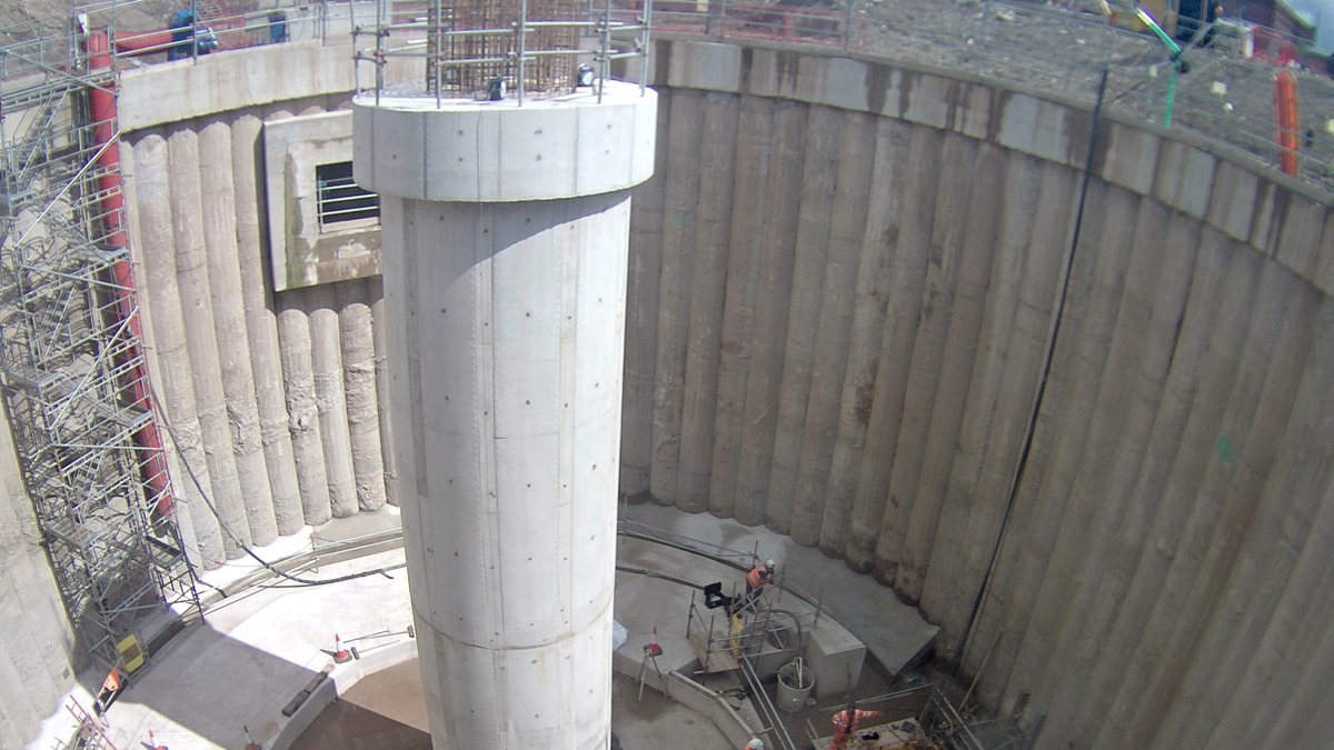
Hathershaw shaft with VacFlush column complete – Courtesy of Laing O’Rourke
A central VacFlush column from CSO Group Ltd was constructed to provide self-cleansing of the shaft as well as structural support for the roof. The column was constructed in situ to ensure a monolithic concrete structure is cast and provide a near air-tight solution. The precast roof will be supported using 12 (No.) prestressed radial beams sat on elastomeric bearings. The beams will span between the pile capping beam and the VacFlushTM column and are restrained in position using a reinforced concrete diaphragm wall. The diaphragm is precast and lifted onto the capping beam to limit work from height. The precast concrete roof panels will then be placed on the beams and a thin screed is cast in situ to seal the roof system against water ingress.
Bardsley Pumping Station (800m3 storage): Project summary
Previously a wastewater treatment works, the existing site now comprises of a CSO and a network pumping station, that passes forward flows to the Oldham Interceptor Sewer, approximately 3km to the north of the site. The CSO discharges to the River Medlock. Network modelling analysis provided several solutions to reduce discharge at Bardsley CSO; for which the optimal solution was selected in collaboration with United Utilities.
A conventional offline detention tank with a pumped return was constructed to the West of the existing site. Construction comprised of a bifurcation chamber, built around the live discharge pipe from Bardsley CSO, a 12.5m diameter 15m deep smoothbore segmental shaft, a 2m x 3m x 2m deep chamber to house the rising main manifold and valves, and an 80m long 150mm diameter rising main returning to the CSO.
Key elements and challenges
Ground conditions at the site were made ground over sands and gravels before changing to Pennine rock at around 10m. Early ground water investigations found that the water table was significantly high across most of the site (4m) and one borehole found subartesian water may be present. This led to the selection of a composite methodology for the construction of the shaft. To limit horizontal water seepage into the shaft, a sheet pile perimeter was driven to rock level around the tank. This greatly reduced the risk posed by the highly permeable sand and gravel layer. The segmental shaft was then sunk using the caisson method and a 2m reinforced concrete plug was cast.
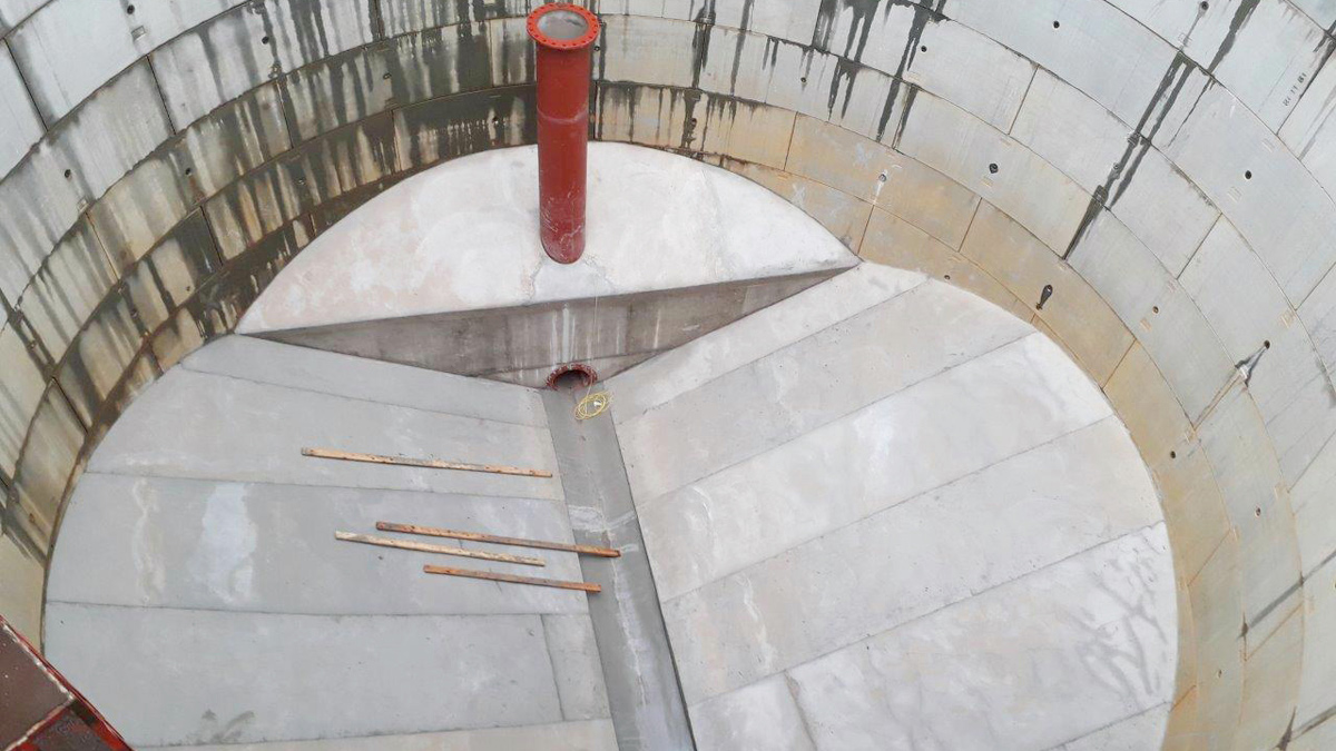
Steep concrete benching complete – Courtesy of Laing O’Rourke
Steep concrete benching provides self-cleansing of the shaft and additional self-weight which removed the requirement for a base plug. The precast roof system comprised of 2 (No.) precast beams spanning the diameter of the shaft and precast concrete panels that will span between the beams and the shaft wall. As the detention tank is located in a field adjacent to a valuable private property, professional and transparent third-party liaison undertaken by UU and LiMA’s customer service manager was required to negotiate and land purchase and agree construction methodology with the land owner. This proved key to the success of the project.
Online storage downstream of Snipe Clough: Project summary
Unlike Hathershaw and Bardsley, the solution downstream of Snipe Clough CSO was developed as online storage as this provided the most economical solution. This presented unique challenges when dealing with live sewer flows at great depths (>20m). A shaft was constructed on the Oldham Deep Interceptor Sewer approximately 1.3km down-stream of Snipe Clough CSO. The solution took the form of a flow control chamber with a central dividing wall.
Prior to the installation of the shaft, the line of the existing tunnel needed to be determined to a great degree of accuracy, as flexibility in the design could only give minimal tolerance. Manned entry into the existing shafts either side of the proposed works identified the tunnel line, and CCTV footage showed a significant radius was present. Further investigations using a theodolite gave an accurate line and this was verified using a probing rig, where a 100mm core was taken from the top of the tunnel.
An 8.2m diameter 24m deep smoothbore segmental shaft was sunk using caisson method to approximately 15m and then underpinning proceeded to ensure no excessive forces were transferred to the tunnel. As the tunnel was uncovered, the top half was removed, and a steel flume was inserted. This enabled the remainder of the concrete tunnel to be removed and the flume to span across the excavation.
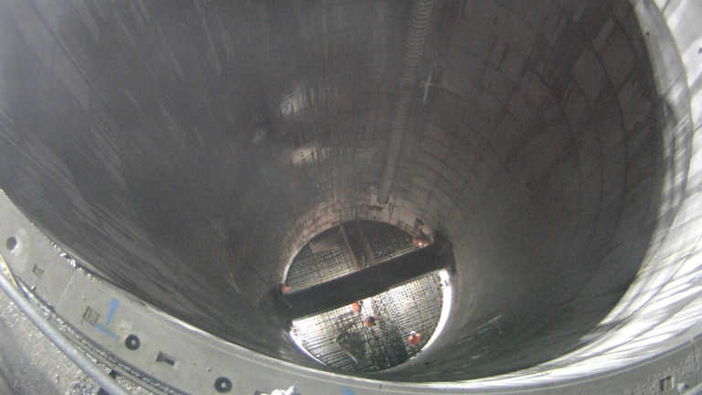
Installation of base reinforcement and flume – Courtesy of Laing O’Rourke
The flume could transfer full flows expected in the tunnel and additional level monitoring was provided upstream to give warning of unexpected rising levels in the sewer. Shutdowns of upstream penstocks were required to install and remove the flume, and this required close collaboration with the client operations team to minimise shutdown time and mitigate safety risks as much as possible.
A reinforced concrete base was cast at the bottom of the shaft with an under-ream to provide additional anti-flotation stability. From the base a reinforced concrete dividing wall was cast. The dividing wall splits the chamber into a ‘dry’ side and a ‘wet’ side. An 800mm square penstock is mounted to the wet side of the wall to provide pass forward control of the online tank. As flows increase in the sewer, water levels rise in the wet side of the chamber. The penstock position is adjusted using level monitoring control.
Medlock Quality Programme – Supply chain/key participants
- Civil designers & network modelling: Atkins
- Delivery contractor: Laing O’Rourke (LiMA)
- Nereda process: Royal HaskoningDHV
- Tunnelling & shafts: VJ Donegan Civil Engineering Ltd
- Mechanical installation: Suprafilt Ltd
- Mechanical installation: Alpha Plus Ltd
- Switchgear & MCCs: Lloyd Morris Electrical Ltd
- Software & system integration: Tata Consultancy Services
- Electrical installation: Interface Contracts
- Smoothbore segmental shaft construction: Joseph Gallagher Ltd
- VacFlush: CSO Group Ltd
- Hathershaw shaft secant piling: Expanded Geotechnical
BIM integration
BIM Level 2 was used across the project and was invaluable. The federated model was used to support all parties involved in the scheme. Examples of benefits from this integration were:
- The inclusion of temporary and commissioning plant aided in the planning and sequencing of the works.
- The inclusion of risk triangles on the model increased awareness of potential health and safety risks.
- As Failsworth is an extremely congested site, clash detection played a vital role in driving detailed design.
Challenges and success factors
Hathershaw is located within a residential area accessed via a small estate road. Minimising disturbance caused by the work was a key priority. A public exhibition was held in advance of the works, and residents were kept updated with progress by regular letter drops and doorstep engagement. This considerate approach resulted in several WOW Award nominations. The project team wished to leave a positive legacy for the community directly impacted by the works, and so at the college, the project team volunteered time and materials to construct a Peace Garden. The project team collaborated with the pupils who contributed to the design.
Summary
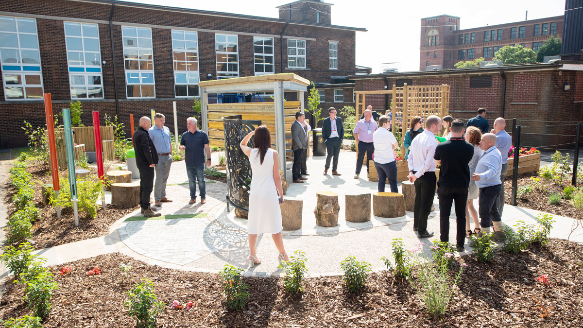
Peace Garden constructed at Hathershaw College by volunteers from the project – Courtesy of Laing O’Rourke
In the face of many challenges the scheme is on track for the Environment Agency regulation deadline of March 2020. When completed Failsworth be one of the first generation Nereda® plants constructed and operated by United Utilities to fully treat the increased FtFT flow.
As of August 2019, all major civils work and mechanical installation is complete. Flows have been turned and the Nereda® plant is in the process of being commissioned to allow the existing plant to be decommissioned. Bardsley and the online storage downstream of Snipe Clough are complete and commissioning is ongoing. The DfMA roof to the shaft at Hathershaw is due to be installed in October. The success of the project is largely attributed to close working relationships between LiMA and United Utilities with collaborative design meetings, collocated working, best for project decision making and honest feedback shared on a regular basis.