
Boston Barrier Tidal Flood Defence Scheme (2019)
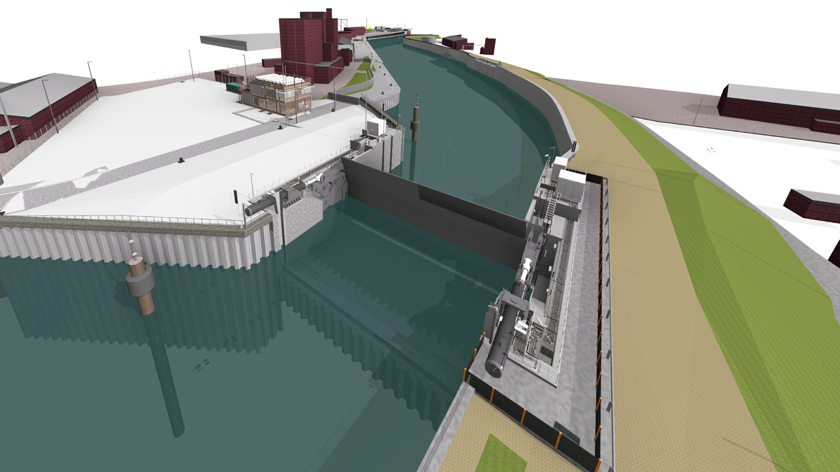
BIM model of barrier structure - Courtesy of BMMJV
Boston Barrier Tidal Flood Defence Scheme is a £100m project for the Environment Agency, delivered by BMMJV (a joint venture between BAM Nuttall and Mott MacDonald), to reduce the risk of tidal flooding to 14,300 properties and businesses in Boston, Lincolnshire. Boston is located on the east coast of the United Kingdom off The Wash and has a history of tidal surges. Extensive flooding has occurred in 1953, 1978, and most recently on December 2013, leading to flooding of over 800 properties, 55 streets, and 79 businesses. The project will reduce the risk of tidal flooding against an event of 1 in 300, or an annual exceedance probability of 0.33% of flooding for the 100 year project lifespan.
Background
The site is located at the tidal section of River Witham known as The Haven. It is upstream of the entrance to the Port of Boston (PoB) but downstream of the entrance to the South Forty Foot drain. This is because a location downstream of the PoB would mean designing the barrier for the passage of cargo vessels whilst a location upstream of the South Forty Foot would sterilise the future aspirations for the Boston to Peterborough Wetland Corridor. The optioneering and final location of the barrier was the subject of public inquiry in 2017.
In order to effect the flood defence, this location required a new floodwall to link the Maud Foster sluice at the left downstream end of the site to the Right Bank. The flood defence runs through the Port of Boston including a new set of gates and refurbishment of the entrance to the dock, the new barrier and a new floodwall and defence raising of the Right Bank.
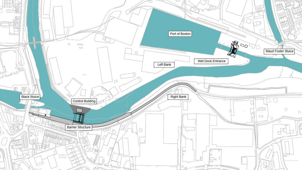
Project site plan – Courtesy of BMMJV
Refurbishment of the dock entrance requires a closure of the dock and temporary works to allow the existing riverside quays to be used in lieu of the main dock during the closure. The main components of the flood defence scheme are:
- Rising sector gate (RSG): 362T, 26m wide (25m clear width) and 11m high gate to raise during tidal surges and protect Boston from flooding, with two 55T hydraulic rams.
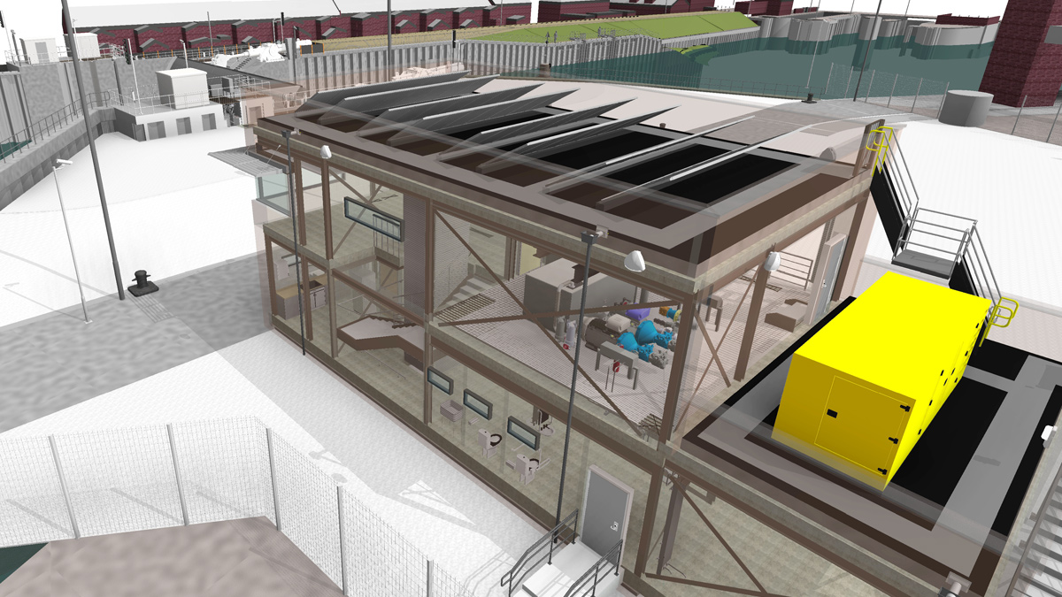
- Barrier control building: New building to provide control of operation and maintenance of the barrier, and to provide storage for the plant and equipment.
- Wet dock entrance: Construction of a new 18m wide and 11.5m high vertical sector gate (VSG) to widen the existing wet dock entrance at the Port of Boston.
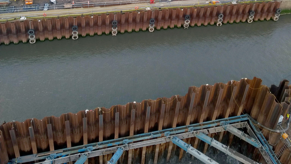
- Left Bank works: Construction of new 830m long, 2m high flood wall, and 590m chainage of 19m long anchored sheet piled Quay Wall within the live Port of Boston (PoB) and three piled load relief platforms for port crane operations during the wet dock closure period.
- Right Bank works: Construction of 525m chainage of 19m long anchored sheet piled flood defence wall and new landscaped embankment to enhance the social and environmental impact of the project.
- Scour protection: Installation of scour protection mats on the bed of the river upstream and downstream of the RSG, to provide protection against scour, arising due to the significant reduction of the river cross-section.
Undertakings
BMMJV were appointed in August 2017 by the Environment Agency to deliver the project under the Water and Environment Management (WEM) Framework. ECC PM and cost consultants for the contract are Turner and Townsend and Jacobs act as independent technical advisor for the Environment Agency.
Barrier structure
The main component of the barrier structure is the 26m wide by 11m high rising sector gate (RSG). Engineering precedent for this type of structure is scarce. The Thames Barrage is similar from an operational perspective but not design, whilst the Ipswich Barrier is similar but 30% smaller and had not been commissioned at the time the project started. A key challenge for the Boston project was to capture learning from Ipswich through the JV gate designer, Hollandia, who fabricated the gate at Ipswich as well as the client and ITA teams so as to advance the design and buildability of the structure. The use of virtual prototyping in BIM, prefabricated rebar and precast units to form the curved recess for the gate were innovations in the civil-structural design. Virtual ‘clash detection’ of rebar in the extremely heavily reinforced zone of interaction between the hydraulic cylinder, gate pivot and wall rebar was deployed to significantly reduce the potential for critical delay in fixing the barrier wall steel. The virtual model was also heavily utilised in HAZID, and access, lifting & maintenance workshops to develop the MEICA design including a ‘virtual commissioning’ to practice the actual commissioning procedure which is a critical path activity.
Bypass channel – Courtesy of BMMJV
A significant design development from Ipswich was a change in hydraulic cylinder orientation from sub-vertical (Ipswich) to horizontal at Boston. This was an intricate trade off with the Boston concept, sacrificing mechanical advantage and a structurally more complex wall arrangement in lieu of superior workflow to move the gate to the maintenance position (gate upside down to allow full access for repairs, re-coating and the like on a 5 yearly cycle). Again, the BIM model was deployed in HAZID and ALM sessions specific to this operation with bespoke details and tools identified as being required through the process.
Routine access to 4 (No.) 2m diameter shafts required for transferring hydraulic and MEICA infrastructure on the Ipswich Barrier Scheme was designed out and replaced with a U shaped frame which can be lifted out and maintained as a single unit. This not only improves the safety of maintenance but also improves the resilience of the hydraulic design compared to the specified cast in pipework solution at tender stage.
The RSG operation is controlled via the new control building, allowing positioning of the gate in the open, closed, and maintenance position.
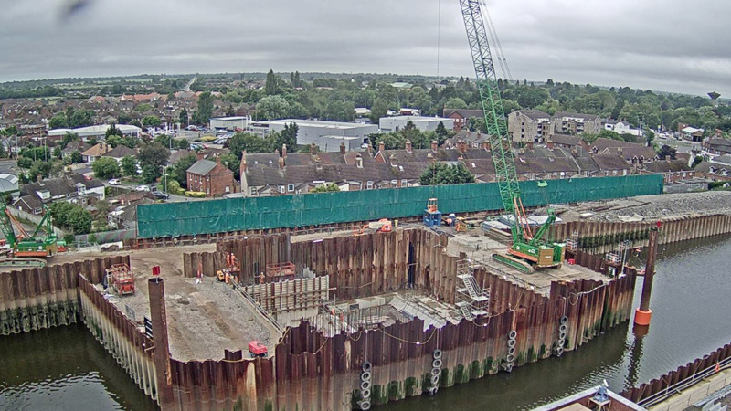
Still from Boston Barrier webcam – Courtesy of BMMJV
Barrier Control Building
The building to control the barrier included the main power supply, hydraulic power pack, hydraulic oil tank, standby generator, electrical panels and control room as well as staff facilities, stores and spares. All of the critical infrastructure to operate the barrier must be protected against flooding even if part of the defence had failed. The original concept had the plant on the ground floor which required a flood proofed building and hold down piles to resist flotation. It also had vulnerabilities around building penetrations and flood proof doors (which also constrained options for packaged plant).
Control building north-east – Courtesy of BMMJV
In order to accommodate noise attenuation for the standby generator the building footprint was high whilst there were also intricate details and troublesome operations with respect to exhausting and refuelling the generator. Using the BIM model, the whole project team developed and agreed an alternative concept to flood proof critical plant on the first floor with the generator outdoors on a balcony. This resulted in packaged plant, easy telehandler access through a roller shutter door, smaller footprint (less noise attenuation), deletion of the hold down piles, easy refuelling and exhausting of the generator and improved fire safety by storing the fuel with the generator.
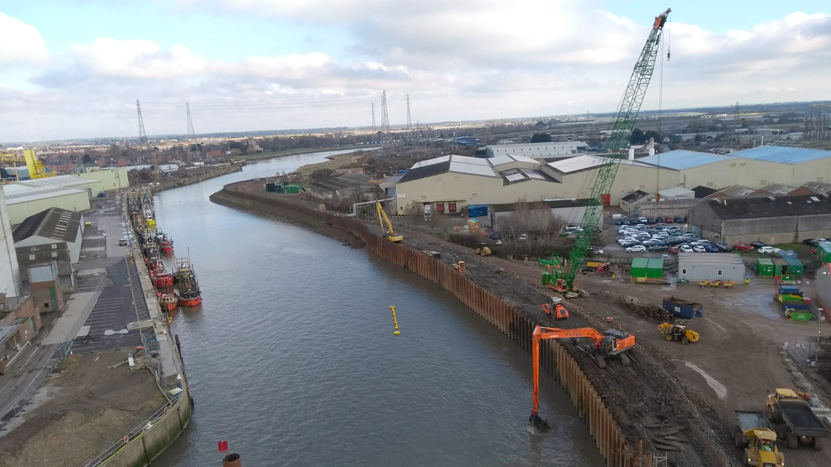
Left Bank
The Left Bank of the river is the Port of Boston estate. The new floodwall is sufficiently close to the existing quay wall that the required 100 year design life could not be guaranteed through reliance on the existing wall. As a result, a new anchored sheet piled quay wall is required to protect the flood wall as well as three new crane pads to allow the riverside quays to be used during closure of the main dock. The design utilises steel tube anchor piles at 4.2m centres with flexibility in position so as to avoid anchor ties of the existing wall. Where new crane pads are required, the quay wall is anchored to the piled platforms.
The floodwall is a reinforced concrete structure with 6 ancillary gates (currently under design). Marine furniture including bollards and fendering have also been designed.
Right Bank
Construction on the Right Bank entails a new river wall, with 525m of 19m long anchored sheet piles, two emergency layby facilities and significant landscaping works.
The team will be introducing and propagating a population of the nationally rare wild plant, Boston Horsetail, as well as installing information panels and decorative wall panels to improve the biodiversity of the area and provide an enhanced environment for the public to use.
The landscaping panels will have designs moulded in to the face of a cast in situ wall, representing the history and heritage of Boston.
Downstream – Left Bank and Right Bank – Courtesy of BMMJV
Wet Dock entrance
The most challenging element of the project is the Wet Dock entrance. The existing lock is to be widened from 16m to 18m with construction of a new set of hydraulically actuated vertical sector gates and a control/plant building with similar MEICA challenges to the barrier.
The key to success is establishing temporary works for breaking out the existing lock for the widening whilst permitting turning of vessels immediately downstream of the works that would normally occur in the main dock. This will be achieved by constructing upstream and downstream cofferdams in the lock and filling the chamber with fill to provide sufficient space downstream of the works to turn vessels. The new gates will be constructed in a third cofferdam cell in the centre of the lock.
“The work the team has put into the BIM virtual project has ensured a clear and concise picture has been presented to all members of the team. It has been used to unlock efficiencies including crucial changes to the design of the control room, hydraulic systems and future O&M ways of working as well as ensuring efficient and effective design to avoid buried obstruction on a well-developed and ever-changing Port site. The BIM model has proven to be fantastic communication tool, conveying the changes we are bringing to Boston much better than traditional 2D drawings, especially when talking to those without engineering knowledge or background. We have used it extensively in both professional presentations as well as a key part of our communications package with the local interest groups and primary and secondary schools supporting our STEM and community engagement works”
Adam Robinson, EA Project Director – Boston Barrier.
Status
The main barrier will be installed towards the end of 2019 with works to the Port of Boston and installation of the remaining flood defences taking place throughout 2020-21.