
BRP – Elan Valley Aqueduct (Bleddfa) – Birmingham Resilience Project (2017)
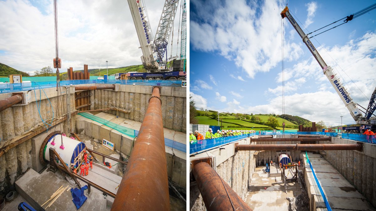
(left) By combining the tunnel drive pits and connection cofferdams, the team made significant savings while simplifying construction and reducing the delivery programme and (right) the three sections will bypass key locations of the aqueduct to improve resilience of water supply to Birmingham using this 100-year old asset - Courtesy of GHD
At the height of the industrial revolution, Birmingham’s population was booming. Between 1800 and 1900, the city had grown substantially. An innovative solution was needed to provide its residents and industries with safe drinking water. James Mansergh had identified the Elan Valley as a source for water. With Birmingham located so far in land, the city needed a viable way of transporting the water. Enter the Elan Valley Aqueduct. The original aqueduct was built between 1893 and 1904. Fast forward over 100 years and the aqueduct still provides drinking water from the Elan Valley to Severn Trent Water’s customers in Birmingham. The aqueduct transports high quality water entirely by gravity.
Background to the works
Having supplied water for over 100 years, the aqueduct was beginning to tire in three key locations and Severn Trent identified the need to protect the structure. Severn Trent explored the possibility of internal repairs but the time available between aqueduct draining and restoring supply made this unfeasible. Having ruled out internal repairs, Severn Trent identified that the best option would be to replace three sections offline and use the planned shutdowns to drain the aqueduct and connect into the existing pipeline.
Barhale and nmcn (now Galliford Try), forming the BNM Alliance, were appointed to deliver these new sections across three locations in Bleddfa, Nantmel, and Frydd Wood in the town of Knighton.
Design and construction
The new aqueduct bypass sections are segmentally-lined circular tunnels constructed using an earth pressure balance tunnel boring machine (TBM).
- Bleddfa: The new Bleddfa tunnel section passes below the Welsh hills through the Siltstone bedrock. This was excavated using a Herrenknecht TBM. GHD began work on the project in August 2015 developing Severn Trent’s feasibility designs. Working closely with BNMA, they have simplified the tunnelling operation and removed a shaft.
- Nantmel: This bypass section passes below ground. The solution for this section of the scheme has been simplified. Instead of constructing a cofferdam here, BNMA will use open cut techniques to remove construction of a cofferdam and drive pit from the programme.
- Frydd Wood: The section in the town of Knighton replaces the Frydd Wood conduit. The new tunnel runs under the Scheduled Ancient Monument of Offa’s Dyke. The project is located adjacent to a Site of Special Scientific Interest (SSSI) meaning it is crucial that environmental impacts are minimised. This was particularly important with the tunnel drive shaft located just metres from a SSSI area and the reception pit located on the hill side above the town.
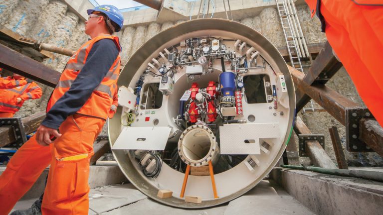
BNMA’s upgrade of the 113 year-old Elan Valley Aqueduct consists of tunnels constructed using an Herrenknecht earth pressure balance tunnel boring machine – Courtesy of GHD
Innovative design and construction
The project involved a number of innovative approaches in design and construction. These solutions reduced cost, time and environmental impacts.
Reinforced soil wall: The original solution was envisaged to use battered slopes. Instead, the team introduced a near vertical reinforced soil wall on the steep slopes of the downstream connection. It is the biggest of its kind built in the UK in 2016.
TBM drive pit designs: The new sections needed to connect into the existing aqueduct during shutdowns and have flows switched to the bypass. The shutdown duration for connecting was limited to five days including a day to drain down the aqueduct and one day to recharge. In addition, the team were limited by highway access constraints, steep side slopes, limited working space, and a minimal area for stockpiling excavated material within the site boundary.
The original solution for these connections involved constructing TBM drive shafts to build the new sections.
A solution to the connection pit and TBM drive pit cofferdam was developed, which involved a secant piled wall around the connection point between the new tunnel and the existing EVA. This methodology removed the need for an additional launch shaft and protected the aqueduct at all times. It also allowed quick reinstatement of flows and reduced shutdown requirements.
Finally, the design minimised work within this period to ensure delivery to programme and allowed for adaptation on site to suit the geometry of the existing tunnel.
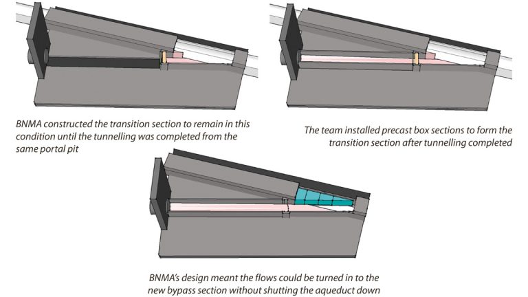
EVA design schematics
Building the connection and TBM drive pits
BNMA completed a bulk dig above the crown of the aqueduct. They then built the piled wall around the portal, maintaining safe clearance from the aqueduct. This involved installing the sheet piles via dig and push methods to protect the live pipeline.
To monitor any impacts of ongoing work on the aqueduct, BNMA also installed real-time monitoring systems using Shape Accel Arrays and vibration monitors to monitor any impacts.
They inspected the tunnel and conduit to assess the existing integrity of the structure along the full length of the site compound. The aqueduct was then protected with a concrete wrap.
Forming connections and transition channels
BNMA then constructed the new connection sections. This involved constructing in situ concrete walls and a base for the connection section. They also installed double stoplogs ready to keep flows along the existing pipeline route.
During the shutdown, BNMA removed the concrete wrap and cut into the existing pipeline by removing the roof and wall. After connecting the transitional section, the team then made good the surfaces and poured the remaining section.
A key part of this shutdown involved preparatory activities for the remaining works. GHD carried out a 3D laser scan of the area for fabrication of the deflector wall. Meanwhile, BNMA installed stainless steel dowels for the deflector wall, placed double stoplogs, and installed a temporary roof structure. Finally, STW reinstated flows through the aqueduct.
BNMA then installed precast concrete box sections to form the transition section. These box sections were pre-benched to form the channel to the required 3D transition cross-section.
Diverting flows into the new tunnel
The next step focused on diverting flows into the new tunnel. BNMA developed an innovative solution that meant the flows could be diverted into the new tunnel while the aqueduct was in service.
This involved removing the temporary roof, placing precast concrete diversion blocks into the live flow using guide rails and removing the stoplogs. BNMA then placed the precast concrete roof complete with permanent access portal.
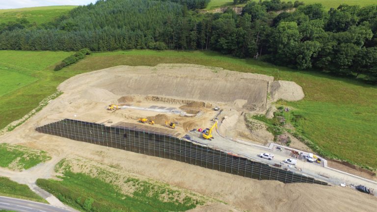
GHD designed the largest reinforced soil wall constructed in 2016 – Courtesy of CADSITE Services
Conclusion
The team has helped secure significant time and cost savings through a range of innovative designs at each project site. By combining the TBM drive pits and the connection cofferdams, the design removed two deep shafts from the scope. The reinforced soil wall design helped the project achieve a cut-to-fill earthworks balance. At Frydd Wood, the team removed a deep shaft by changing the philosophy of hydraulic design.
On all three sites, the project introduced a combination of cast, in situ concrete and benched precast concrete units to remove the need for large pre-fabricated lightweight steel sections. The project solution included a staged excavation and exposure of the existing structure. This removed the need for internal propping by installing a concrete surround. This also kept the aqueduct operational during excavation.
The method used across all the sites allows flows to be turned while the aqueduct is live. This has minimised the work during shutdown periods, protecting the project programme and continuity of supply for Severn Trent’s customers.