
Farlington WTW (2017)

Trant Engineering Ltd
Portsmouth Water’s Farlington WTW dates back to 1909 and provides potable water to more than 280,000 people and many businesses in the Portsmouth and Havant area. Farlington’s supply is derived from the springs, which are believed to be the largest spring source in Europe. In April 2015 Portsmouth Water issued a tender based on an outline design for treatment and process facilities to address potential cryptosporidium and discharge mitigation issues. The solution developed consisted of (i) an ultraviolet irradiation facility at Farlington WTW for the inactivation of cryptosporidium (to be installed within a former existing membrane filter building) and (ii) a wastewater recirculation facility to separate supernatant flow from process solids and return it to the head of the works. The NEC3 ECC Option C (Target Cost with Activity Schedule) contract was awarded to Trant Engineering in August 2015.
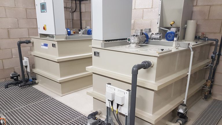
Polymer makeup equipment – Courtesy of Trant Engineering Ltd
UV treatment
The former membrane filtration plant (MFP) was installed in 2003 as the only viable DWI Approved process to remove cryptosporidium oocysts from the filtered water prior to entering the service reservoirs. The membrane plant sub modules were deemed to be nearing the end of their serviceable life. The original MFP plant comprised 6 (No.) identical treatment streams plus provision for a future additional treatment stream. Trant Engineering Ltd was approached by Portsmouth Water, with an outline design comprising of 3 (No.) UV streams (duty/duty/standby).
Following a design review by Trant Engineering it was decided to investigate an alternative approach based on the provision of 5 (No.) UV reactors streams (duty/duty/duty/duty/standby). The revised design drastically reduced both the construction and operational risks, provided greater operational flexibility and security and enabled the phased migration from the former membrane treatment process to the new UV treatment process whilst delivering considerable CAPEX savings.
The UV plant design was created using 3D modelling and hydraulic analysis by Trant Engineering. One of the key elements of the design was to minimise interference with the operation of the existing MFP and due to the innovative design it was possible to install, test and commission the first UV treatment streams whilst leaving the existing MF streams fully operational.
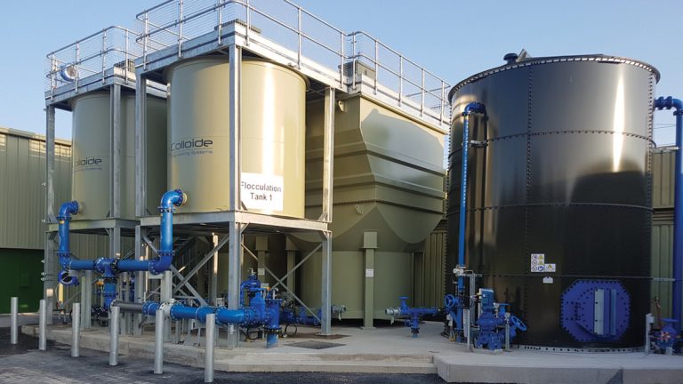
Lamellas, transfer pumps and sludge balancing tank – Courtesy of Trant Engineering Ltd
Following the successful testing and commissioning of this first UV streams, flows up to 50Ml/d through the new UV plant enabled the first of the MF streams to be taken out of service, dismantled and removed. This then allows the second UV stream to be installed, tested and commissioned to provide a further 25Ml/d of UV treatment capacity. This process was then repeated until all 6 (No.) MF streams were removed and the 5 (No.) UV treatment streams fully operational. These carefully programmed sequential operations ensure a gradual migration from MF treatment to UV treatment whilst providing secure and continuous treatment to supply.
The 5 (No.) identical 25Ml/d UV reactors installed under this contract are low pressure units from ATG Technology each with a 316 stainless steel reactor chamber housing 16 (No.) 800W Amalgam UV lamps with automatic wiper system, validated UV monitoring. Each of the UV streams is provided with a magnetic flow meter, inline axial mixed flow booster pump, manual and actuated valves together with the associated 316 stainless steel pipework. Each stream also has a dedicated UV local control panel and UPS.
Washwater discharge mitigation
Wastewater discharge from site is generated from backwashing of the existing rapid gravity filters (RGFs), rainwater, and sample water. There are 13 (No.) RGFs, which periodically require backwashing to maintain water quality. The backwash water drains through channels from the filters, through existing chambers and used to bypass 2 (No.) washwater holding tanks and exit site.
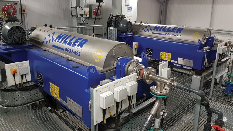
Duty/standby centrifuges – Courtesy of Trant Engineering Ltd
Trant Engineering, as part of the same contract took the outline design and again applied value engineering to design and install the scheme as described below:
- The 2 (No.) existing washwater holding tanks were not used for more than 20 years, with the manual inlet penstocks to each tank closed, and the manual bypass penstock valve open. The washwater tanks and penstocks have been refurbished, to allow flow to enter the tanks. An overflow weir is also installed in the reception chamber and the bypass penstock left open. In each tank there is a variable speed drive (VSD) submersible pump installed, with a common discharge that sequentially pump the contents of the tanks to the 2 (No.) new lamella thickeners.
- 2 (No.) new lamella thickeners (duty/duty) take flow from the backwash tanks, whereby solids gravitate into each integral thickener, and supernatant (clarified water) will then gravitate to the existing inlet chamber at the head of the works if <10NTU. If supernatant is >10NTU then flow will be directed back to the washwater tanks. Polymer is dosed into the feed line to the lamellas, from dosing plant (duty/standby pumps) located within the newly installed centrifuge building.
- Sludge (raw water solids), is removed by the 2 (No.) lamella sludge transfer pumps (duty/standby) via actuated valves and pumped into the new sludge balancing tank. The sludge balancing tank contents are mixed by the new external sludge balancing tank external mixing pump.
- 2 (No.) centrifuge feed pumps (duty/standby) will be installed, feeding the 2 (No.) new centrifuges (duty/standby) located with the new centrifuge building.
- Sludge is then dewatered to a minimum of 15% dry solids w/w, where the ‘cake’ drops into a skip beneath the centrifuges, and the centrate (liquid waste) is either recycled to the washwater tanks or discharged to the sewer pipeline. Polymer is dosed into the feed line to each centrifuge, from dosing plant (duty/standby pumps) located within the centrifuge building.
- Polymer is made up using duty/standby makeup units from which the lamella and centrifuge dosing pumps draw from to their respective systems.
- Water supplying the polymer makeup units, polymer dilution (dosing pumps), hose points and centrifuge washdown is boosted by a new service water booster set located within the UV building.
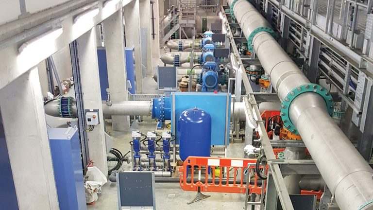
During construction – 3 (No.) UV Streams in service – Courtesy of Trant Engineering Ltd
Summary
In summary, this has been a challenging project – in part due to Farlington being a prime site serving Portsmouth – but has been highly successful due to the open communication and collaboration on all levels between Trant Engineering and Portsmouth Water. At the time of writing (May 2017), all major works have been completed ahead of programme and handover of the project to the client was due in July 2017.