Esholt STW (2024)
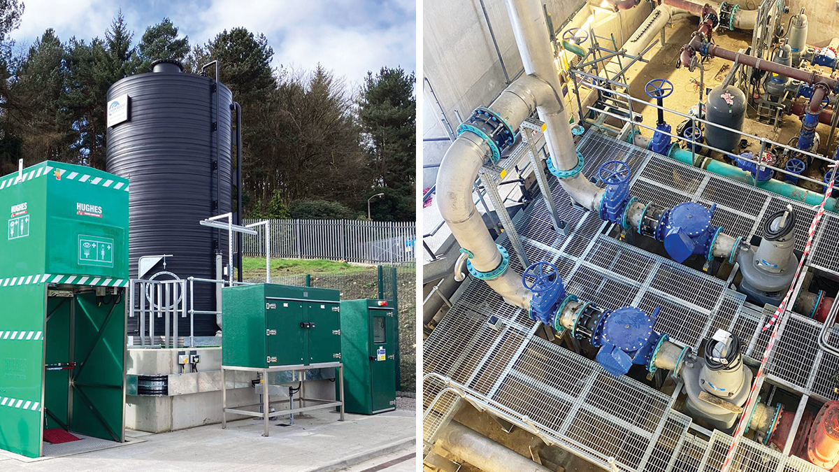
(left) Primary ferric delivery area and storage and (right) re-purposed dry well for new dirty backwash PS - Courtesy of MMB
Yorkshire Water’s Esholt Sewage Treatment Works is located northwest of Leeds and serves a population of approximately 400,000. The STW treats the majority of sewage flows from Bradford and parts of northern Leeds, with a flow to full treatment of 3200 l/s. The project driver is part of the Water Industry National Environmental Programme (WINEP), which aims to reduce overall phosphorus concentrations in the final effluent to 0.5mg/l, thereby improving water quality in the River Aire. To achieve this new consent, YWS contracted Mott MacDonald Bentley (MMB) to undertake the detailed design, construction and commissioning of the work. The project scope included a new coagulant dosing system and tertiary treatment to ensure the new phosphorus consent was met.
Coagulant dosing system
The dosing system involved the implementation of a 40m3 external ferric sulphate dosing tank with a chemical dosing system, with the point of application prior to the primary settlement tanks. MMB utilised the YWS standard product which is a DfMA solution in partnership with framework supplier, Northern Pump Suppliers Ltd (NPS).
The ferric storage tank, the dosing kiosk (which came pre-assembled with all the mechanical equipment and control panel), and the point of application cabinets were all manufactured off-site and could be dropped into place in delivery.
This reduced multiple different interfaces and enabled the site team to build all the other elements ready for the delivery. The ferric dosing system was placed strategically at the bottom of an existing hydro-turbine to utilise the turbulence caused by the screw in operation which provided optimal mixing for the chemical; no additional mixing was required.
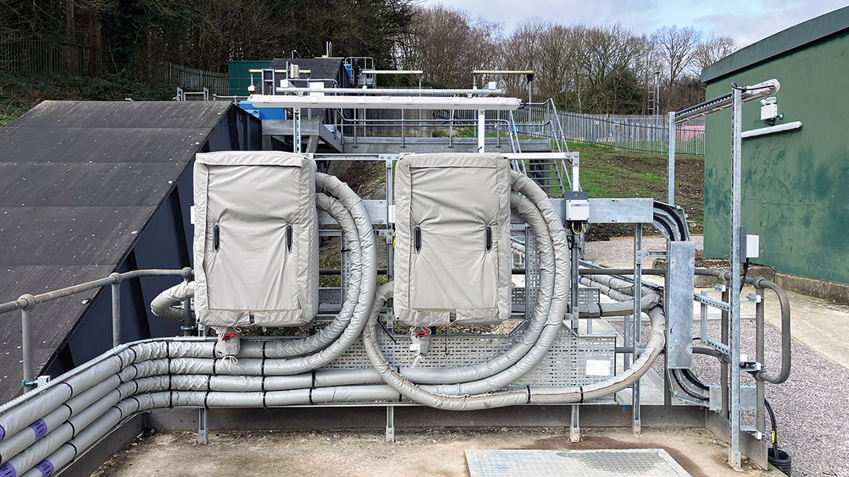
Primary ferric point of application cabinets – Courtesy of MMB
Challenging designs & re-use of existing structures
Due to the additional ferric being added into the sewage, the site required tertiary solids removal (TSR) to capture any remaining particles before going out to river, ensuring compliance with iron consent limits. Esholt has an existing TSR which consists of 12 deep-bed sand filters cells (DBSF). The DBSF works by allowing effluent to flow down through the bed, with residual solids being captured by the granular material in the bed. In 2015, the works was damaged by an extreme flood, and subsequently the DBSF has remained out of service ever since.
To avoid the need to install new TSRs, the proposed scope included the refurbishment of the abandoned DBSF. Using this ‘build less’ approach saved on capital costs and reduced embodied carbon emissions, but did introduce its own challenges.
Following the previous abandonment, part of the dirty backwash system had been re-purposed for alternative use, meaning that a new solution for returning the backwash flows was required. To address this, a new pumping station was proposed to regulate flows back into the process. Due to the poor ground conditions and high-water table, the design required the pumping station to be of wet caisson construction. The pumping station featured a 280m-long rising main, directing flows back to the existing humus tanks. The pumping station itself was planned to be 12m in diameter and 7m deep, located adjacent to the DBSF.
During design development, MMB reviewed the need for the proposed storage requirement, agreeing a slightly different operating regime for the pumps and DBSF backwash control. As a result, the team identified an opportunity to re-purpose an existing dry well structure nearby. By adapting this structure, they could house the new return pumps without the need to construct an entirely new pumping station.
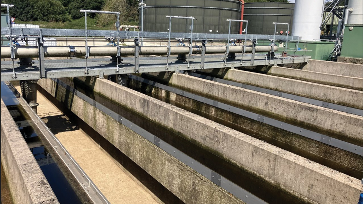
Deep bed sand filter, post refurbishment – Courtesy of MMB
Laser scanning
To verify this opportunity, and to ensure that the detail design could be completed with minimal changes, the team utilised GeoSlam Horizon. This handheld laser scanning technology took half a day to survey the existing dry well, and enabled MMB’s digital delivery technician to model the output in Revit. The model was then exported to virtual reality (VR) in which the project team held collaborative review sessions to confirm the design and ensure that the proposal would be compliant against the clients engineering standards. This also aiding access lifting and maintenance reviews with the client to ensure the refurbishment included aligning the design to the new client engineering specification.
By challenging the design requirements, MMB took out the need for a new pump station by re-purposing the existing structure. This removed the difficult caisson construction and by doing so achieved substantial costs savings for this element of work, and enhanced safety conditions for the construction team. This approach also significantly reduced the embodied carbon footprint. The team utilised the Mott MacDonald Moata Carbon Portal to undertake rapid calculations to understand the benefits of the proposed change, showing a capital carbon saving of ~248 tCO2e.
Rising main
The 280m rising main that directed dirty backwash flows back into the existing humus tanks was originally proposed below ground. The pipe was routed along the Industrial Emissions Directive (IED) boundary and the initial assessment concluded that the pipe required dual containment to mitigate the risk of any pollution.
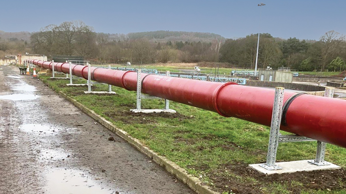
Dirty backwash rising main – Courtesy of MMB
MMB worked collaboratively with the client to better understand the risk and consequence of a failure, as the media contained within was backwash water and not sludge, which is typically with focus under IED. In addition to this, a review was undertaken on programme and cost impact, as well as the risks during the construction phase.
The outcome of this review was an agreement with the Environment Agency to undertake a more pragmatic approach. The carbon saving calculated on the Moata Carbon Portal tool is estimated to be ~37t CO2eq moving from a dual contained below-ground pipe, to an above-ground single skin ductile iron pipe.
MCC
The existing MCC in this area had reached the end of its asset life and was insufficient in terms of capacity. To meet the power and control requirements of the refurbished sand filters, the new backwash arrangement, and associated equipment, a replacement was essential. However, the location of the existing MCC posed challenges, in that it could not accommodate the new MCC while complying with the latest Engineering Specification.
To achieve the upgrade, MMB proposed a hybrid approach to the design. Instead of installing the entire new panel in a separate GRP kiosk raised above the flood zone on a steel frame, the team opted for a more efficient solution. They integrated sections of the new MCC within the existing building, ensuring compliance with current specifications, minimising the length of the MCC which required a new structure. This reduced not only the kiosk size but all the periphery infrastructure including civils works, raised steel frame and security fencing.
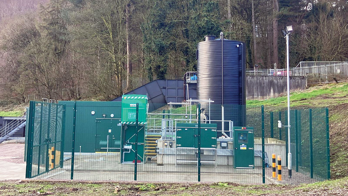
Side view of primary ferric dosing compound – Courtesy of MMB
Esholt STW: Supply chain – key participants
- Designer & delivery contractor: Mott MacDonald Bentley
- Dosing system subcontractor: Northern Pump Suppliers Ltd
- Chemical dosing trays subcontractor: APT Marine Engineering Ltd
- 3D printing subcontractor: Hyperion Robotics UK Ltd
- Electrical installation: Circle Control & Design Systems Ltd
- DBSF mechanical refurbishment: De Nora Water Technologies UK
- MCC platform subcontractor: AJ Engineering & Construction Services Ltd
- Thinwall stainless steel pipework: GTS Nitrogen Services Ltd
- Systems integration: Actemium
- Civil engineering/site engineers: Day Civils Ltd
- Access platforms subcontractor: GT Fabrications
- Security fencing subcontractor: Burn Fencing Ltd
- MCC security kiosks subcontractor: Technocover Ltd
- Electrical panels: Technical Control Systems
- Flow controls: AFFCO Flow Control (UK) Ltd
- Pumps: Xylem Water Solutions
- DI pipework: Electrosteel Castings (UK) Ltd
3D concrete printing
To take the electrical ducts around the site and between the two panels for power and control cables, multiple large scale draw-pits were required at changes of direction. These draw-pits, typically measuring 2m2 by 2m deep, typically involve in situ concrete casting with 0.25m-thick walls. Their construction can be carbon-intensive, time-consuming due to intricate formwork, and pose safety risks for the construction team working in excavations over extended periods.
After meeting at a Yorkshire Water-led Net Zero event, MMB began forming a strategic relationship with Hyperion Robotics. Hyperion create 3D printed structures with a cementitious grout, printing only what the structure actually requires to be structurally integral. Early discussions used the proposed draw-pits as a test case of how their innovative 3D printing technology could support the water industry’s need for innovation and a drive towards Net Zero.
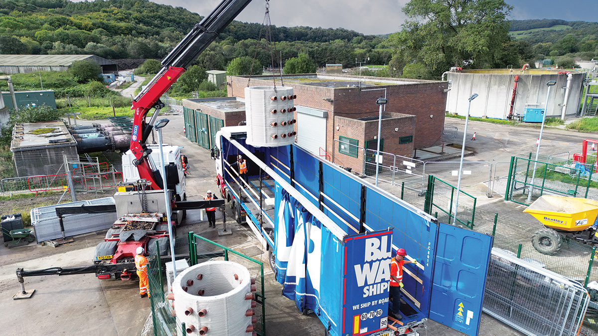
Delivery of 3D printed draw-pits – Courtesy of Mott MacDonald Bentley
The process involved working with Hyperion to create a bespoke design, to allow incorporation of the specific electrical duct penetrations and angles, and sizing of the chambers. This process reduced the materials required by 40%. Collaborative reviews were held with MMB, Hyperion, Tarmac and Yorkshire Water to ensure adequate buy in to this new technology.
3D concrete printing involved printing cementitious grout in layers, by using this technology the time taken to print the 2m high 1.9mØ draw-pits required at Esholt was only two hours. This DfMA approach also had huge safety and programme benefits as the time required working within excavations was significantly reduced since the site team could directly lift the draw-pit into the excavation from the wagon.
The technology provides improved quality control and ensures precise application to meet the exact dimensions in a controlled environment. The 3D-printed design achieves a 40% reduction in embodied carbon, a 10% cost reduction, and a 50% improvement in programme for drawpit construction, compared to conventional in situ.
Progress
Esholt STW is on track to meet its compliance date of 0.5 mg/l of phosphorus by December 2024. The scheme has been a success by challenging the design to get the best value for the client but to leave a positive impact on the environment. MMB have kept in touch with the continuously growing construction industry, trialing new technology including utilising laser scans, VR and 3D printing.
Esholt is a prime example of how challenging design and reusing existing structures where possible reduces the impact the construction has and accelerates progress towards a net-zero built environment.
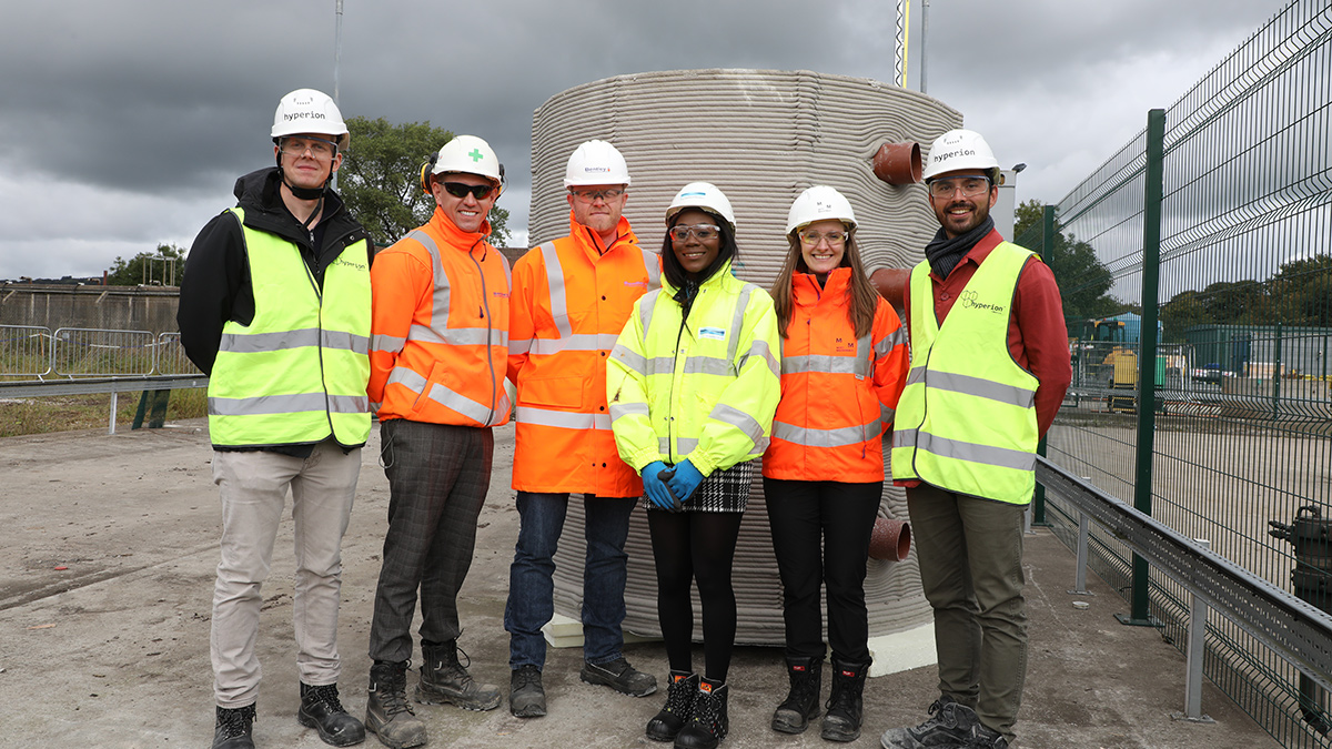
The project team in front of the 3D printed draw-pit - Courtesy of MMB


