Tunstall Reservoir (2024)

Tunstall Reservoir - Courtesy of Esh-Stantec
Tunstall Reservoir is located approximately 5km to the north of Wolsingham, in County Durham. It is an impounding reservoir retained by an earth filled embankment with a central clay core. The dam is approximately 25m high and 300m long. The reservoir was previously used to feed a water treatment works located at the toe of the dam; which is now decommissioned. The reservoir is now used for amenity purposes and to provide environmental compensation flows to the downstream valley. Following a Statutory Inspection under Section 10 of the Reservoirs Act, a number of measures in the interest of safety were recommended by the Inspecting Engineer in order to ensure the safety of the dam.
Section 10 of the Reservoirs Act
Following a Statutory Inspection under Section 10 of the Reservoirs Act, a number of measures in the interest of safety were recommended by the Inspecting Engineer in order to ensure the safety of the dam. These recommendations involved the following:
- Recommissioning the existing siphon that used to feed the works and was no longer in use had to be intercepted and provided with a new route in order to provide additional drawdown capacity to the reservoir.
- Repairs to the lower part of the spillway where the existing blocks were damaged.
- Filling an existing tunnel within the dam structure.
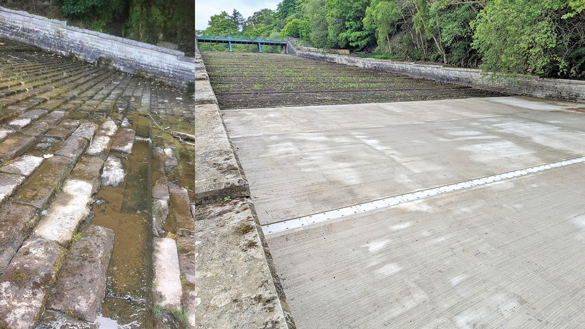
(left) Condition of the spillway blocks prior to the works and (right) new concrete slab with stainless steel protection to the joint – Courtesy of Esh-Stantec
Siphon re-commissioning
Various options were considered at the concept stage in order to restore the use of an existing siphon that was abandoned in the early 2000s when the treatment works were decommissioned. The preferred option involved the following:
- A siphon discharge chamber to break the siphonic effect. This was decided given the uncertainty about the existing system and the significant difference in levels in the downstream leg. Thus, the water would flow by gravity between the chamber and the outfall. This discharge chamber also functions as a thrust block to restrain the thrust acting on the new gate valve that has been installed immediately upstream of the chamber.
- The use of the existing settlement tanks to retain the water and aid to the settlement of suspended solids. A penstock chamber has been provided between the tank and the new discharge point to retain the water for a day before it is discharged into Waskerley Beck once the majority of the sediment has settled.
- Routing the new pipework away from the areas of the embankment that present the most valuable Waxcap habitats. Waxcap mushrooms are rare as they are restricted to grassed areas that are not grazed, and are locally protected in Durham.
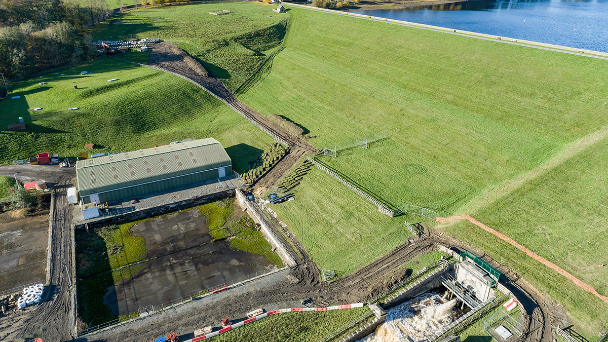
Tunstall Reservoir dam – Courtesy of Esh-Stantec
Spillway repairs
The original Victorian spillway structure is formed by sandstone blocks bedded in concrete. However, the Inspecting Engineer identified that the majority of the blocks in the lower part of the spillway presented signs of wear and tear and needed replacement.
The proposed solution consists of four new reinforced concrete slabs that have been placed over the existing spillway, except the most upstream slab where blocks had to be removed to tie-in with the existing structure and avoid a step. An expansion joint was necessary in the centre of the new slabs. The flexible sealant in this joint has been covered by a stainless steel plate that has been designed to protect the sealant from the predicted high velocities expected in the flows and reduce the maintenance requirements.
A number of groundwater relief drains have also been incorporated into the design in order to capture the emerging groundwater at the lower part of the spillway and both reduce the hydraulic load on the new slabs and improve the long-term reliability of both the new concrete and the remaining sandstone blocks. These discharge to a new headwall in the bank downstream of the end of the spillway.
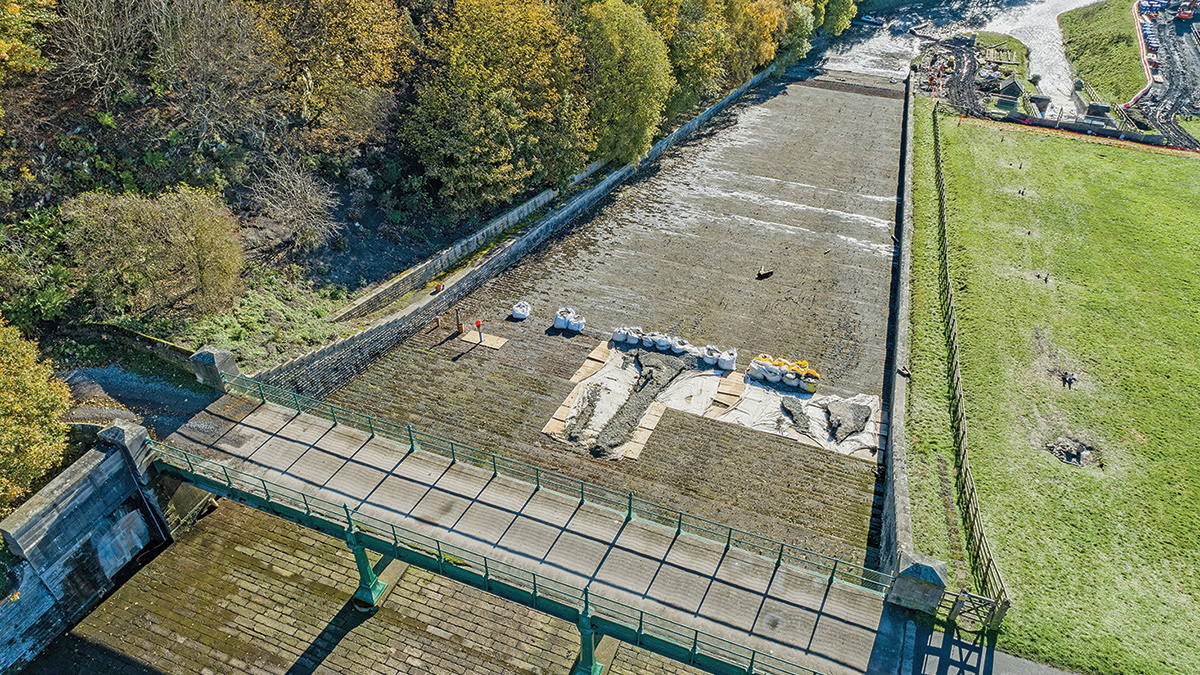
Tunstall Reservoir spillway – Courtesy of Esh-Stantec
Tunnel infill works
When the dam embankment at Tunstall was completed and the filling of the reservoir began, significant leakage was observed through the eastern abutment. A concrete cut-off wall extending into the hillside was constructed in 1879 which significantly reduced the leakage rate. Nevertheless, as some leakage continued, a tunnel and shaft were constructed downstream of the cut-off wall, and an 18-inch cast iron diameter pipe was installed inside the tunnel to capture the leakage and convey it to the treatment works.
Following the Section 10 inspection of the dam in February 2021, a number of Measures in the Interest of Safety (MITIOS) were raised recommending works to address the leakage and the stability of the tunnel. One of these IOS measures recommended to fill the tunnel whilst providing some drainage, as a result of the concerns about its structural integrity and the potential risk to the integrity of the dam embankment and the spillway in the event of a collapse of the tunnel.
The project team scoped and contracted a ground investigation (GI) in Autumn 2022 to investigate the leakage paths into these tunnels.
Based on the findings of the GI and the review of the reservoir levels, it was concluded that the cut off wall is in good condition and that the main flow path goes around the concrete cut off wall. There is also a strong correlation between reservoir levels and the recorded flows, which decrease significantly when the levels are 6 m below the top water level (TWL). This was observed again during the construction works, as the water level was kept 6 m below the TWL for health and safety reasons while there was work ongoing in the tunnel and the spillway.
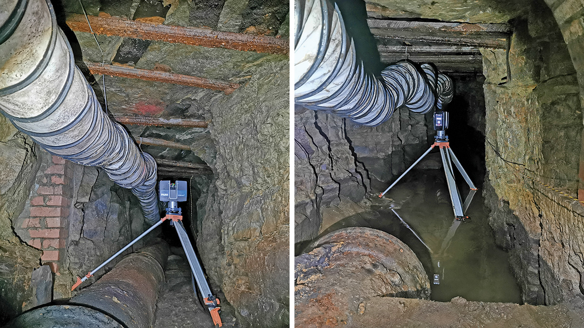
(left) View in the unlined section of the tunnel (notice the beams across the soffit) and (right) view of pipe inlet and partial headwall (notice standing water on the invert) – Courtesy of Esh-Stantec and CC Informatics
Various options were considered during the Concept stage. The option of not filling the tunnel was disregarded as it would not eliminate the potential risk to the integrity of the dam embankment and spillway channel. Filling the entire extent of the tunnel was considered, however it was not preferred due to the significant constraints associated with it. These constraints include the difficult access and requirement to work in a confined space, potential land ownership issues, the presence of a SSSI immediately to the east of the abutment, and the increasing depth to the tunnel as it continues beyond the spillway. For all of these reasons, it was agreed with that filling the extent of tunnel beneath the dam and spillway would be sufficient as that would eliminate the risk to these structures.
Three possible fill materials were considered:
- Cement grout was discounted due to concerns of potential pollution as a low viscosity mix would be likely to mix with groundwater and filter through the rock, causing a pollution incident.
- Foamed concrete was discounted as a result of the potential constraints to place it at the furthest point inside the tunnel, and the remote location of the site and access within the site would further complicate the timely delivery of concrete.
- Expanding geopolymer foam was selected as the preferred material as it reduced the risks associated with grout and foamed concrete; and it had successfully been used by Esh-Stantec in the delivery of other projects.
The expanding geopolymer foam was deemed to be more cost-effective than the alternatives as it offered significant savings to the installation process, because:
- It avoided the risk of pollution and therefore any mitigation works to stop grout leakage;
- Simple installation from a mobile compound, avoiding the need for complex plant and equipment;
- Geopolymer mix materials delivered to site in barrels, allowing for easy storage and transport within the site.
- Installation from the surface via boreholes every 10m along the line of the tunnel.
- Lower carbon footprint that cement based alternatives.
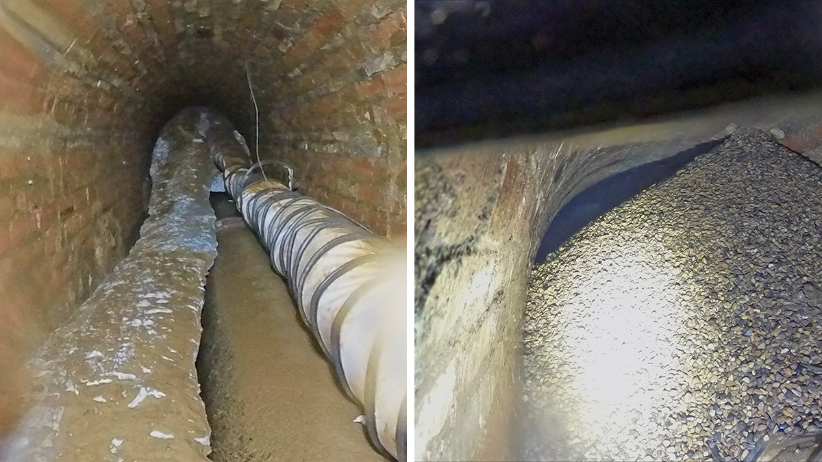
(left) View of the geopolymer in the tunnel, and (right) view of the pea gravel stop end – Courtesy of Esh-Stantec and CC Informatics
The filling was undertaken via a number of injection holes that were drilled from the surface at 10 metre intervals, and expanding geopolymer was injected via these injection points. The progress on site was as follows:
- A pre-drilling survey took place to confirm the condition of the pipe in the tunnel ahead of the works.
- Eleven injection holes were drilled along the dam embankment and across the spillway.
- Prior to the injection, after the drilling had been completed, high resolution cameras were used in each injection hole and a drone survey was carried out to confirm that there was no damage caused to the pipe and that the expanding geopolymer would not enter the pipe.
- Pea gravel was introduced through the final injection point in order to create a mound that would stop the advance of the geopolymer and prevent it from blocking the pipe. The use of the gravel mound avoided the need to carry out works inside the tunnel with the associated risks of working in the confined space.
- Once the project team was satisfied that the drilling had not cause any damage to the pipe, the injection began, advancing at 10 metres per day on average.
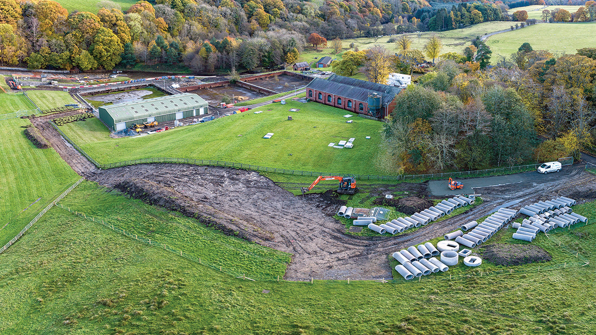
Overview of the siphon diversion route in preparation for the works – Courtesy of Esh-Stantec
Tunstall Reservoir MITIOS: Supply chain – key participants
- Principal designer & contractor: Esh-Stantec
- Esh Group
- Stantec UK
- Geopolymer injection subcontractor: Geobear Ltd
- High resolution cameras & drone survey: CC Informatics
- Confined space entry specialist: MRS Training & Rescue
- Ground investigation: Ian Farmer Associates
- Topographical survey & laser scan of tunnel: Academy Geomatics Ltd
- Pipework modifications: UTS Engineering
- Steel fabrications: JHT Fabrications Ltd
Conclusion
The contract has been delivered by Esh-Stantec and the recommendations in the interest of safety made by the Inspecting Engineer have now been addressed. The siphon will provide additional drawdown capacity to the reservoir in the event of an emergency, the damaged part of the spillway has been repaired to a satisfactory standard, and the potential risk of collapse of the tunnel has been removed.
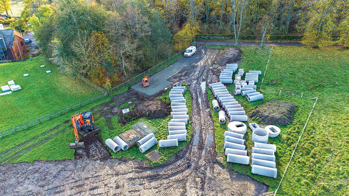
Tunstall Reservoir staging area - Courtesy of Esh-Stantec


