

Guildford STW (2025)
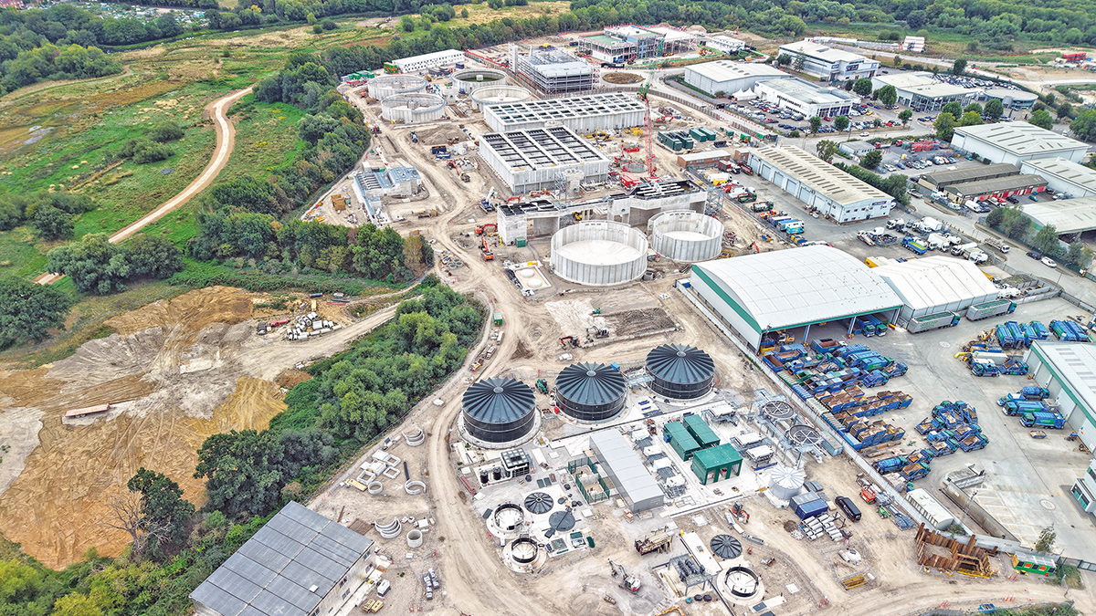
Figure 1: Guildford STW site in August 2025 - Courtesy of BAM
Guildford, the county town of Surrey, sits a commutable 30 miles south west of London and 70 miles from the south coast. Boasting a castle, a cathedral, a picturesque town centre and a university, it is surrounded by Green Belt countryside. The River Wey flows through the town centre and then northwards through water meadows where it provides the outfall for the STW. The Wey eventually discharges into the Thames. The current STW serves a population equivalent (PE) of around 107,000, but the town has a growing population which is expected to grow to circa 125,000 PE by 2041.
Background
The town and immediate area are currently served by a sewage treatment works established at the turn of the last century and upgraded over the years. It is located beside the River Wey, to the north of the A3 trunk road and north of Guildford town centre. It lies just south of Slyfield Industrial Estate. The current STW has a capacity to cater for a population equivalent of around 120,000.
Guildford Borough Council’s Local Plan adopted in 2019 allocates a site to the west of the River Wey wrapping around the eastern side of Slyfield Industrial Estate for mixed use development. Part of the 40 Ha allocated site is currently occupied by the existing sewage treatment works.
Weyside Urban Village is a mixed-use regeneration project which will provide some 1,500 new homes, new community facilities, Gypsy and traveller pitches and 6,500m2 of additional light industrial and trade space. 11Ha of the site are allocated for waste management purposes. The plans include a new council depot, a public recycling centre and a new, relocated sewage treatment works.
In order to bring the development site forward, within the plan period to 2034, Guildford Borough Council (GBC) have entered into partnership with Thames Water Utilities Ltd (TWUL) to build the new STW as the first phase of the redevelopment. The new location is slightly further north on the eastern edge of the Industrial site and is a brownfield site, formerly a gravel quarry and subsequently a landfill tip.
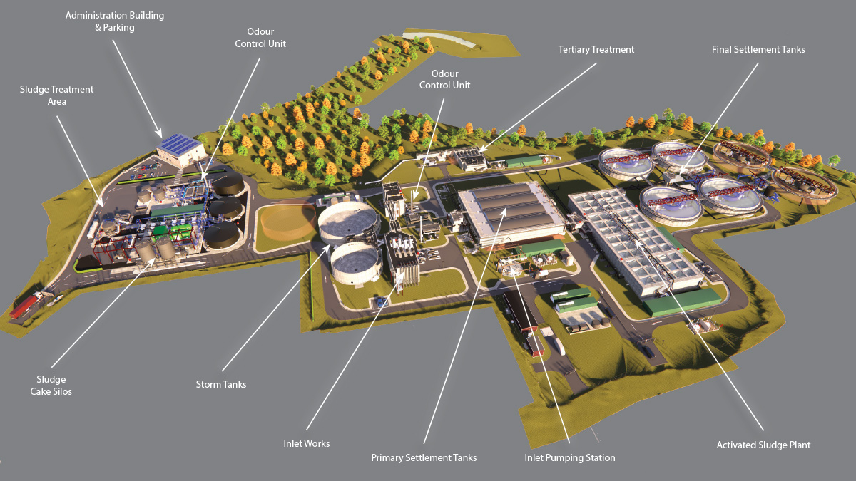
Figure 2: Site overview: BIM model of new Guildford STW – Courtesy of BAM Enpure JV
The new sewage treatment works allows for an increase in capacity to serve a population of 125,000 allowing for predicted population growth in the town and surrounding area as well as more stringent effluent discharge standards.
The new site also includes areas within the new works for future expansion and increased treatment capacity as need arises.
Previously in Water Projects
The scheme to build a new sewage treatment works (STW) in Guildford is now mid-way through construction. This article provides an update to the project following on from previous articles published in Water Projects. In 2023, Enpure Ltd’s Project Delivery Director Shaun Christopher described in detail the process and assets being provided in the new works and in 2024, Dan Russell, BAM’s Operational Lead, gave an update on the progress of the project one year into the construction.
This article also covers some of the planning considerations and requirements for the scheme.
Contract
In 2021 TWUL awarded a contract to a BAM-Enpure Joint Venture to design, build and commission a new STW for Guildford, and once operational, to de-commission the existing works. BAM-Enpure Joint Venture (JV) is a non-integrated Joint Venture, formed specifically to combine experienced civil engineering contractor BAM with the process engineering MEICA specialism of Enpure, to deliver a turnkey solution for TWUL.
Construction began in the spring/summer of 2023 with BAM undertaking design and construction of the civils works and Enpure providing process and MEICA design and installation. BAM have employed Arcadis as their main civils designer and the JV has let a number of specialist sub-contractor design packages alongside.
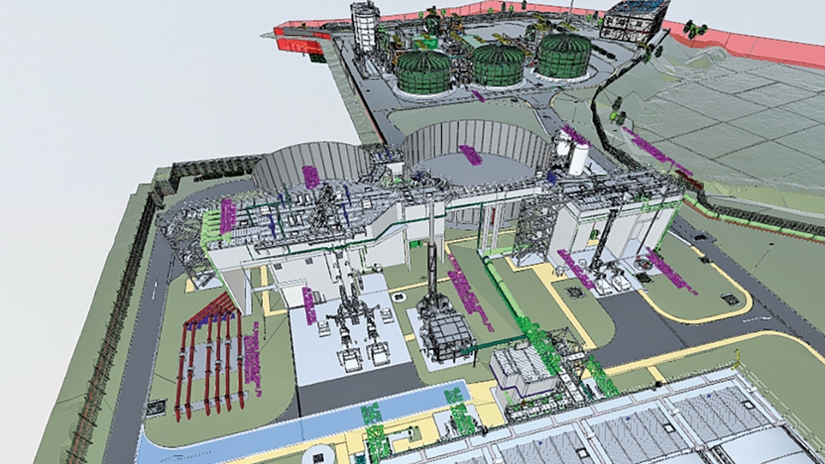
Figure 3: 3D design using a model hosted by Arcadis, image from Autodesk’s Navisworks viewer – BAM Enpure JV & Arcadis
The project
The project consists of the following:
- A transfer tunnel.
- An inlet pumping station.
- Inlet works screening.
- Primary settlement.
- Activated sludge treatment.
- Final settlement.
- Tertiary treatment of final effluent.
- Chemical dosing facilities.
- Storm storage tanks.
- Import cess and sludge facilities.
- A new control centre.
- New welfare building.
- Outfall into the River Wey.
Timeline
- Phase 1: Ground improvement: Started summer 2023 and completed February 2025
- Phase 2: Civil engineering: Started summer 2023 with completion due in late 2025.
- Phase 3: Mechanical & electrical engineering: Started autumn 2024 and is due to complete summer 2026.
- Phase 4: Commissioning: Starts winter 2025 and is due to complete in spring 2027.
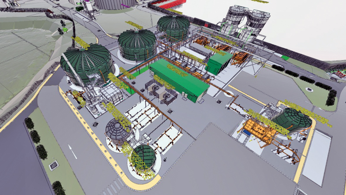
Figure 4: 3D model of the sludge processing area – Courtesy of BAM Enpure JV & Arcadis
Developing the site
The new site comes with additional challenges in that it is brownfield site formerly used for gravel extraction and then landfilled through the 1960s, 70s and 80s, with mainly domestic and some commercial waste. The site is classified as a waste development such that the local planning authority is Surrey County Council (SCC).
The planning permission granted was subject to a number of conditions and commitments, not only relating to the siting and development of the STW itself such as visual impact, odour, noise and traffic generation, but also to the remediation and reuse of the landfill site. Plans and construction methods needed to ensure that there was no temporary or permanent environmental damage to the surrounding area as a result of the impact on or disturbance of the buried waste material and that operatives working on the new STW were protected from any ill effects of the landfill during operation of the site. The landfill also poses particular constraints and hazards during the construction phase.
The strategy for the site was to leave as much of the landfill waste in situ and build above and through the waste. A detailed remediation strategy formed part of the planning requirements. The plan set out how the construction and operation phases of the project would manage issues of ground water and ground gas, potential ground water contamination and leachates, contaminated solid material including asbestos, and short- and longer-term settlement of the landfill.
Dan Russell’s case study in Water Projects 2023 provided a detailed description of the use of a combination of ground improvement and foundation techniques, which consisted of:
- Rapid Impact Compaction (RIC) to improve ground strength and reduce long-term settlement of the landfill.
- Vertical Rigid Inclusions (VRI), a displacement concrete pile technique which provided support for roads, lighter structures pipes and ducts.
- Driven concrete piles bedded in the London Clay below the land fill to support large structures, tanks and pipelines.
Figures 5 (below) show the historic gravel extraction map and depth of landfill determined by ground investigation – both images were extracted from the project’s Detailed Remediation Strategy.
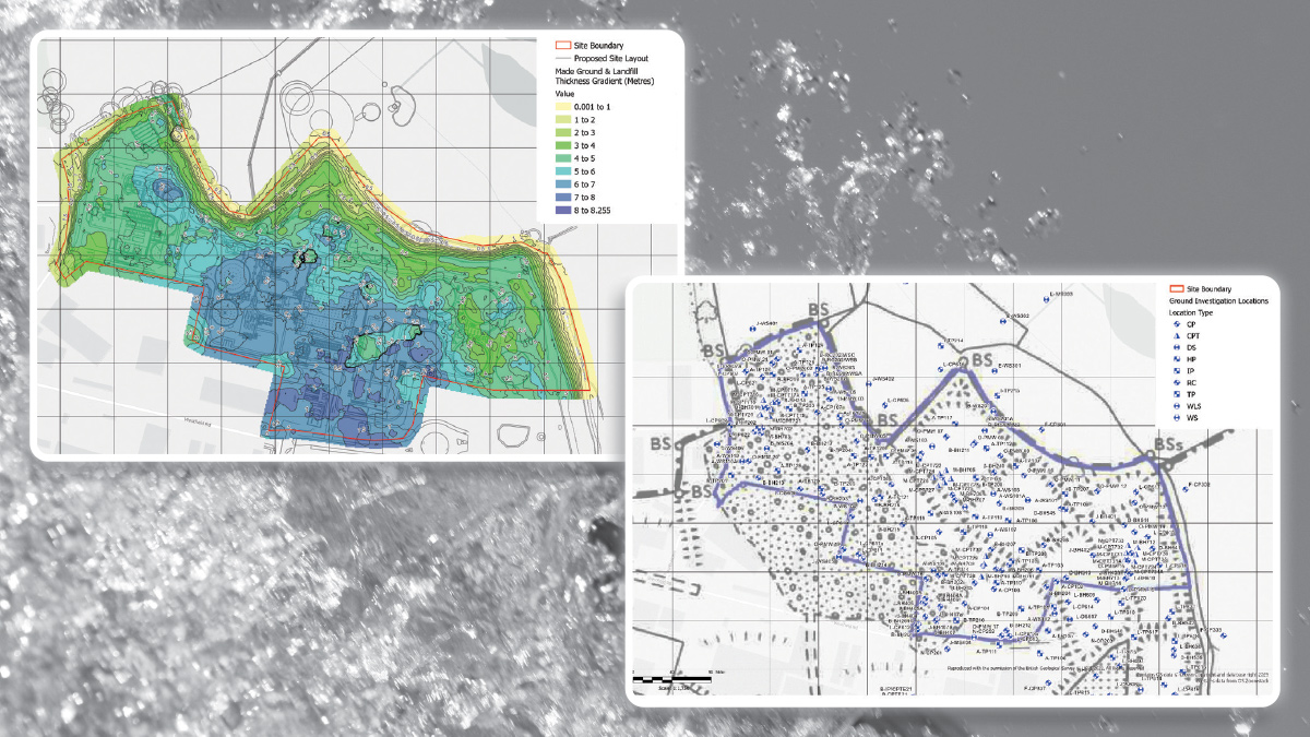
Figures 5: (left) Spatial variation in landfill thickness 2023 and (right) historic site layout (1976) with present day boreholes overlaid – Courtesy of Arcadis
However, the impact of the waste material goes beyond its bearing capacity. The site was already being subject to long term monitoring for ground gas and groundwater quality by Thames Water to provide a baseline for the project. Additional boreholes were sunk and a Groundwater & Ground Gas Monitoring Plan was approved by the local authority. Daily and continuous automatic remote monitoring was undertaken during the ground improvement and excavation phases with trigger levels set and exceedances reported back to SCC and a requirement for quarterly summary reporting. Monitoring will continue during commissioning of the site at less frequent intervals.
Asbestos: Asbestos had been discovered in a third of samples taken during the ground investigation and so a monitoring regime was established. Air sampling around the perimeter of the site ensured any airborne particles were detected and works could be stopped if necessary. Proximity asbestos monitoring and identification of asbestos material in excavation has also been used extensively during excavation across the site. The project used Socotec to undertake asbestos monitoring and testing.
Ground gas: A ground gas protection design has been necessary to reduce risk of ground gas entering occupied buildings, kiosks, tanks and chambers where operational or maintenance access is undertaken. A ground gas design protection strategy was set out by Arcadis with PAGeo Contracting Ltd providing expert advice and a detailed ground gas design, PAGeo then supplied gas dispersal matting, venting components and gas membranes. Both the strategy and the detailed design for ground gas protection have been submitted to and approved by SCC.
Independent verification of the gas protection installation has been provided by MTS Ltd as verification of the installation and subsequent reporting to SCC is a planning condition.
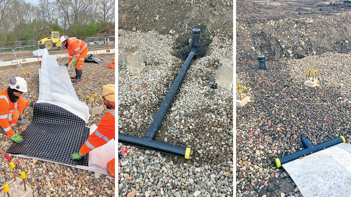
Figure 6: Gas protection void former being laid on stone blanket prior to tank base blinding, Connections to vents at tank perimeter – Courtesy of BAM
Surface drainage: On-site surface drainage has been carefully designed such that new impermeable areas are positively drained to the site drainage system to remove the risk of a spill causing environmental pollution. This surface water is then fed into the inlet pumping station for processing through the works. As the permeable area of the site has been greatly reduced this also significantly reduces leachate mobilisation.
Biodiversity: Another planning condition is the provision of Biodiversity Net Gain (BNG). In conjunction with GBC, the project provides 10% net biodiversity gain by use of on-site planting and off-site enhancement of the land directly to the north of the new STW. A Site of Natural Green Space, biodiversity enhancements to an area of farmland, and a marshy meadow along the River Wey are being provided.
The Environment Agency have also constructed a new fish pass in this area allowing fish to migrate around Old Bucks Weir.
Guildford STW: Civils works supply chain – key participants
- Main contractor: Bam Nuttall Ltd
- Planning consultant: Adams Hendry Consulting Ltd
- Civil engineering design: Arcadis Group Ltd
- Boreholes & testing: Geo-Environmental Services Ltd
- Asbestos monitoring: Socotec Ltd
- Rapid impact compaction: Cofra Ltd (Boskalis Group)
- Vertical rigid inclusions: Foundation Piling Ltd
- Concrete piling: Aarsleff Ground Engineering Ltd
- Temporary works specialist: Mabey Hire Ltd
- Temporary works specialist: MGF Ltd
- Tunnels & shafts: Joseph Gallagher Ltd
- In situ concrete works: Kelly Formwork Ltd
- In situ concrete works: DJ Civils Ltd
- Precast concrete manufacturer: FLI Precast Solutions
- Precast concrete manufacturer: A-Consult Ltd
- Pipe supplier: Electrosteel Castings (UK) Ltd
- Pipe supplier: Saint Gobain PAM UK
- Soil processing: Remediation Waste Management Services
- Concrete supplier: Heidelberg Materials
- Gas protection: PAGeo Contracting Ltd
- Gas protection system installation verification: MTS Ltd
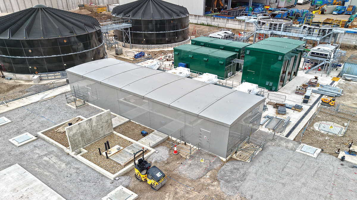
Figure 7: Sludge processing area: MCC kiosk (grey in foreground), sludge blending tanks (top left), poly dosing kiosks (top right) – Courtesy of BAM
Overview of project progress
As of summer 2025, civils works are nearing completion and MEICA fit out has started.
The installation of piled supports has been undertaken, and all major structures are complete. Installation of the below-ground pipework and buried ducting is in progress and the welfare building is watertight and available for equipment installation. Moving towards installation of MEICA equipment, the water testing of structures started in the February of 2025.
Steel staircases and high-level walkways are mostly complete. The inlet screens and grit removal system are in place. GRP tanks for sludge processing are being installed and many control kiosks are in place. Electrical supply buildings are near completion.
MEICA work commenced in February 2025, overlapping with completion of civils to maximise programme efficiencies. Designed alongside the civils elements of the site, the MEICA installation has taken place apace with the first bridges on the final settlement tanks attached, the larger glass coated steel tanks for the sludge area in place, and generators and some kiosks have been installed.
BAM has started the installation of the above-ground pipework and cable pulling in buried ducts, and the fit out of control rooms will commence shortly. Construction of MCC basements has been completed and two of the three MCC kiosk, and power supply and distribution works are nearing completion.
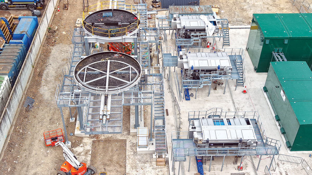
Figure 8: Sludge processing area: (left) the bases for elevated cake silos, (middle), sludge belt presses, and (right) the poly prep & dosing kiosks – Courtesy of BAM
Guildford STW: MEICA works supply chain – key participants
- Main designer/contractor: Enpure Ltd
- CFD analysis: The Fluid Group
- Cake silo: Saxlund International
- PST scrapers & ferric dosing plant: Colloide
- Inlet works & PST odour covers: Power Plastics Ltd
- Grit remover plant: Jacopa
- Escalator screens: Longwood Engineering
- Imported sludge Strainpress: Huber Technology
- Sludge thickening & dewatering: Kent Stainless Ltd
- Odour control plant: Odour Services International Ltd
- FBDA grids & blowers: Xylem Water Solutions
- Cloth pile filters: Eliquo Hydrok Ltd
- Storm tank cleaning system: Sulzer Pumps Wastewater Ltd
- Tank logging system (WASP): JR Pridham Services Ltd
- Glass lined steel tanks: Balmoral Tanks Ltd
- Sludge tank mixing: Landia UK Ltd
Tunnel
A 1.5m diameter gravity tunnel, 1.5km long, transfers flows from the existing works and intercepts minor sewers en route. There are six shafts along the tunnel route, some of which act as junctions between the new tunnel and the existing sewers. Shafts were sunk by Joseph Gallagher using the caisson method and the tunnel was driven between them using a full-face tunnel boring machine, (named Daphne by a local school). The tunnel and shafts were completed in 2024 and the final work remaining are the completion of the large inlet pumping station (IPS), shaft (E2) at the new works and connection of Guildford’s main sewer to the head of the tunnel, which will allow all flows to be diverted to the new tunnel.
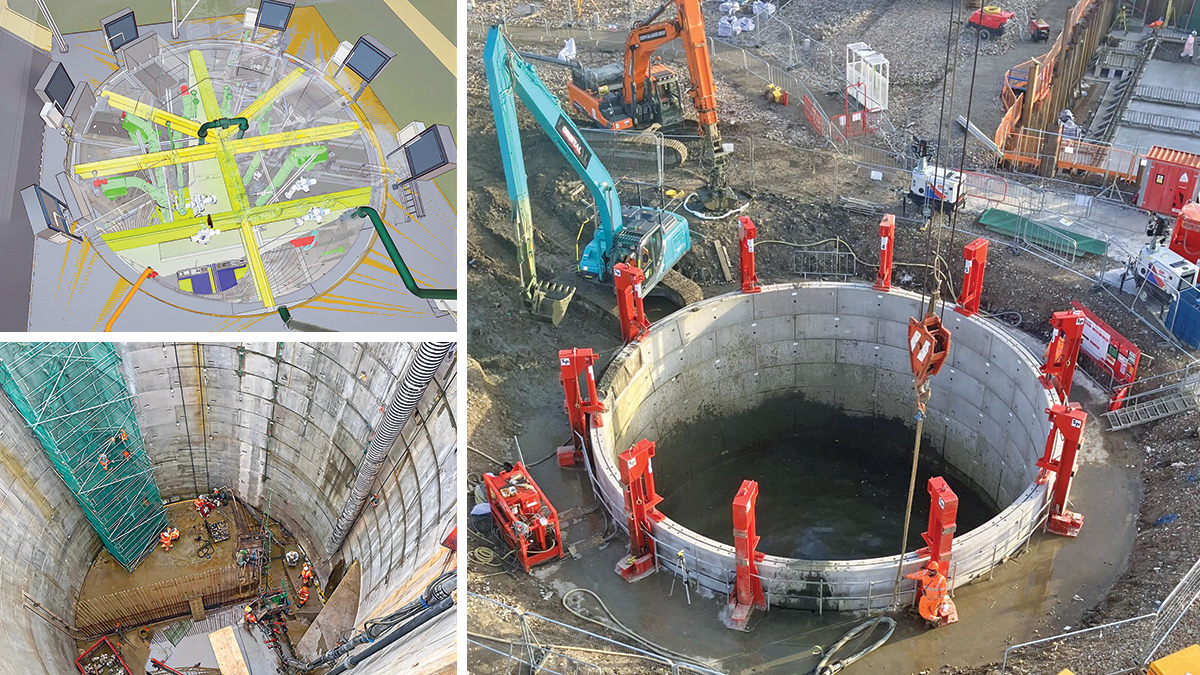
Figure 9: (top left) 3D model of the Inlet Pumping Station (IPS) – Courtesy of Arcadis, (bottom left): steel fixing to IPS internal walls – Courtesy of BAM Enpure JV, and (right): IPS shaft construction – Courtesy of BAM
Inlet pumping station
The new inlet pumping station (IPS) is a 12.5m diameter shaft with a depth of 17m, which houses six pumps with the capacity to lift flows of around 2,500 l/s from the tunnel entry, at the base of the shaft, to the inlet works where all flows are screened. The shaft is complete except for the internal walls and installation of penstocks which allow isolation of half the well at any time for maintenance of the pumps. This will be completed in the autumn of this year.
Storm tanks & inlet works
Two storm tanks provide a combined capacity of approximately 8 million litres to which flow can be diverted to temporarily hold sewage arriving at the new works should flows exceed the capacity of the works. Constructed onto in situ bases, the walls of the storm tanks were prefabricated, placed and post-tensioned by A Consult Ltd.
The inlet works and larger chambers were entirely cast in situ due to lack of repeatable sections and logistics. In situ concrete work for these was undertaken by Kelly Formwork. The inlet screens have been installed and walkways are in place.
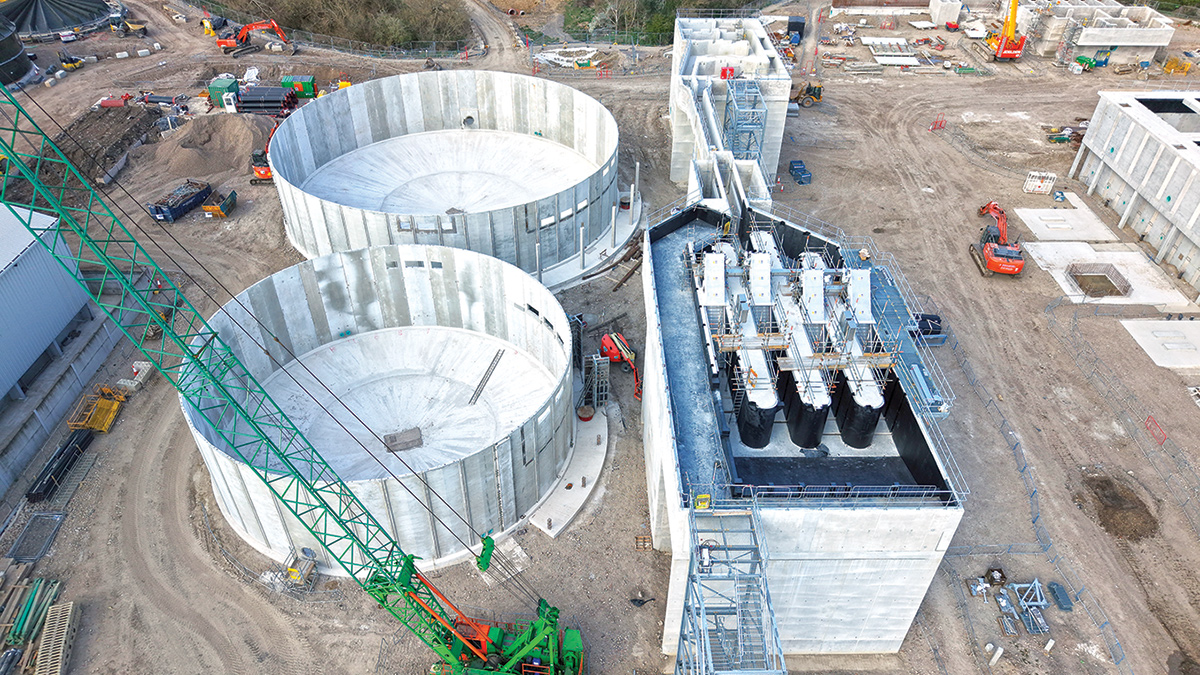
Figure 10: Circular precast storm tanks and Inlet works (August 2025) – Courtesy of BAM
Primary settlement, activated sludge plant & final settlement tanks
Screened flows from the inlet works will then pass through primary and secondary treatment tanks comprising rectangular primary settlement tanks (PSTs) and activated sludge plant (ASP) tanks. The walls for these tanks were designed and supplied by FLI Precast Solutions Ltd and installed by BAM and DJ Civils Ltd on in situ bases prepared by Kelly Formwork Ltd. These tanks are complete with pipework being fitted and the ASP has commenced water testing.
To ensure watertightness of the larger rectangular tanks, Heidelberg Materials and Sika’s concrete technology were used.
Concrete containing Sika WT-200 P was utilised for the PSTs and the ASP. Sika WT-200 P is a combined water-resisting and crystalline waterproofing admixture used to reduce the permeability of concrete, making it suitable for water retaining structures.
Gas protection has been laid under all large tanks. Materials were supplied by PAGeotechnial Ltd and verified by MSL Ltd. Void former mating laid on a bed of single grade 40mm stone provides a preferential escape path for ground gases and is connected to vents at the tanks periphery allowing ground gases to vent to atmosphere.
These tanks are not habitable spaces and only require a dispersal system to discourage any build-up of gas below the large tank bases.
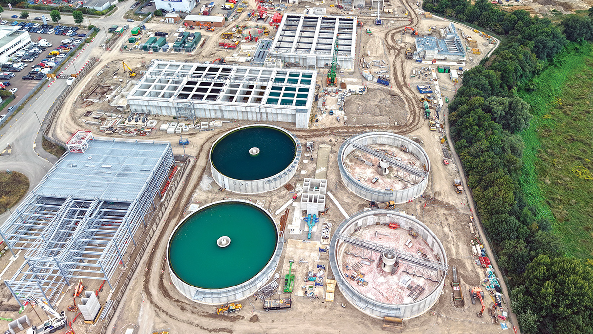
Figure 11: From top: Activated sludge plant, primary settlement tank, and two of the four final settlement tanks – Courtesy of BAM
Final settlement tanks
The four final settlement tanks were also precast, supplied, installed and post-tensioned by A-Consult Ltd onto in situ bases prepared by Kelly Formwork Ltd. The FSTs are complete with bridges and scrapers installed and are currently being water tested.
Tertiary treatment plant & outfall
Following final settlement, flows will pass through final filtration in the tertiary treatment plant before being discharged to the River Wey via new, twin outfall pipes. Civil construction is complete and MEICA installation of cloth pile filters and drums from Eliquo Hydrok Ltd is underway.
The outfall pipework has been fully installed across the water meadow and the headwall has been constructed at the discharge point into the River Wey.
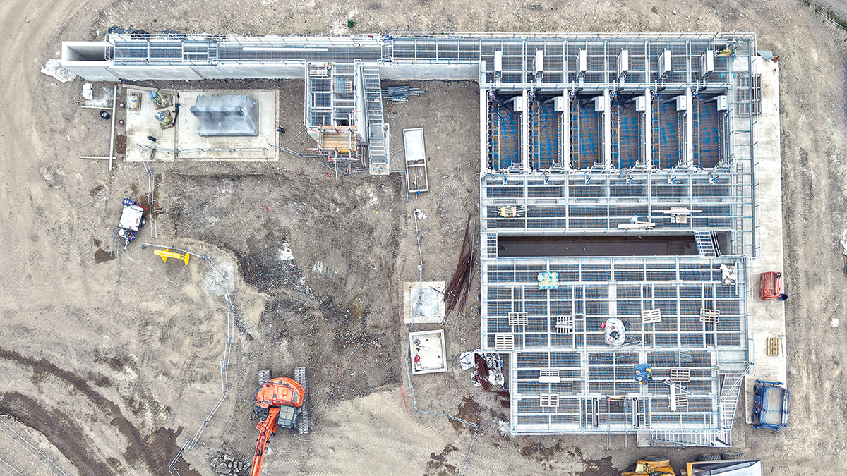
Figure 12: Tertiary treatment plant construction (August 2025) – Courtesy of BAM
Sludge processing
The project also provides a dewatering facility for imported sludge from other small treatment works. This area is nearing completion with the larger coated glass sludge blending tanks in place and the smaller buffer tanks being installed. Gas vent pipes have been installed below the extensive concrete slabs to allow venting of ground gases to the atmosphere.
The sludge belt presses from Kent Stainless Ltd for sludge dewatering and thickening have been installed adjacent to the bases for the elevated sludge cake silos. The silos from Saxlund International have been sized to provide storage of seven days’ worth of processed sludge, which can be discharged to trucks for export from site.
Power & control
Power supply and distribution infrastructure is now in place. The three MCCs have been constructed in sequence and the first two are being fitted out.
Welfare building
A new welfare building houses the automated systems for running the new plant and controlling effluent quality as well as office and mess space for Thames Water staff and operatives. The building is watertight with cladding being installed and the fit out of building fixtures and plant control equipment is in progress.
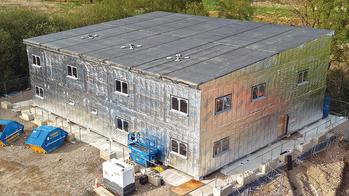
Figure 13: Welfare building housing plant control systems – Courtesy of BAM
3D modelling
Design has utilised a 3D model hosted by Arcadis with each designer adding in modelling information as their design capabilities have allowed. This has enabled precise integration of designers individual input and interrogation of the integrated design
The model is used extensively by engineers on site. 3D modelling has, for example, allowed duct chambers to be precast with precision positioning of cable openings, saving on in situ working and substantially reducing programme on these installations.
Piling & ground improvement
To enable the STW to be constructed on the site without the waste being removed a combination of ground improvement techniques have been employed including driven concrete piles, Rapid Impact Compaction, and Vertical Rigid Inclusions.
The Rapid Impact Compaction work undertaken by Cofra was completed in late summer of 2023. From July 2023 to the spring of 2024, to support the larger structures, tanks and main process critical pipelines, 3500 concrete piles were driven through the landfill into the clay. The design and installation of this piling operation was undertaken by Aarsleff Ground Engineering.
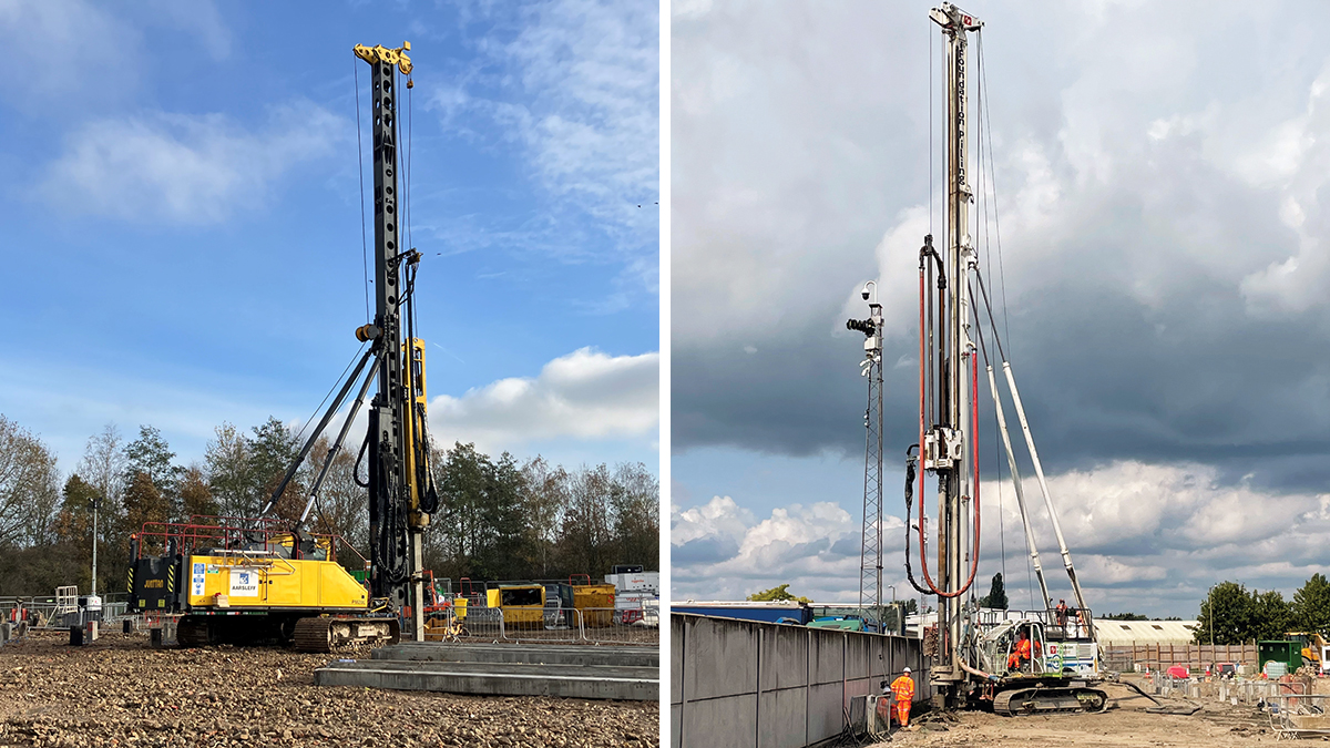
(left) Driving precast concrete piles and (right)Vertical Rigid Inclusion installation – Courtesy of Bam Nuttall Ltd
In areas where settlement criteria were less critical, but needed controlling (for example roadways and minor pipework), a Vertical Ridged Inclusion (VRI) piling technique was used. The system involves displacement drilling a column in the landfill and filling the void with concrete. This works by consolidating the soil around the pile, transferring load to lower layers, thus increasing bearing capacity and reducing settlement over time.
Since 2024 the installation of VRIs by Foundation Piling has been completed with 7500 inclusions installed across the site. During detailed design, the project was able to remove the need for a load transfer platform above the VRIs across much of the site. This was done by detailed analysis of the 3D model to target differing requirements for support and by reducing inclusion spacings, thereby reducing the expected landfill removal by 37,500m3.
The load transfer platform remains below roads, but pipework sits within the grid of VRIs.
The year ahead
Completion of the mechanical works is expected in the first part of 2026 with installation of electrical and control systems expected to complete in the second part of 2026. Dry and wet commissioning will be undertaken sequentially across the site throughout the coming year, ensuring the new works is ready to commence process commissioning.
The final, and arguably most challenging activity, will be to connect the existing sewer network to the new tunnel, diverting flows from the existing STW to the new STW. A series of interventions will be required to intercept the various sewers, along the route of the tunnel, all the whilst ensuring the new STW is performing within strict limits and the existing STW is able to maintain its performance during the ramp down of flows.