


Sindlesham & Bearwood WBS Phase 2 (2026)
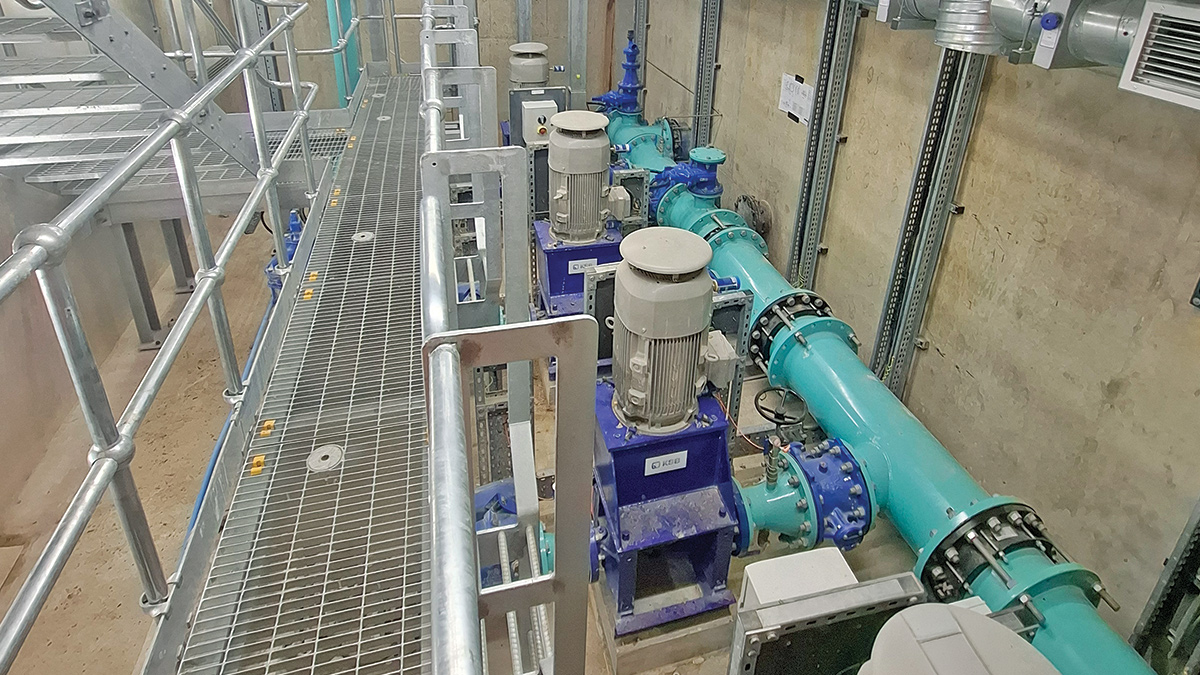
Bearwood WBS - Courtesy of Ward & Burke
Major developments within the Arborfield Garrison are currently being planned and constructed, anticipated to be completed by 2030. These developments consist of 3,500 new residential properties, two primary schools, a secondary school and community facilities. The developments are increasing demand on the clean water network, requiring the implementation of network upgrades and reinforcement to the Bearwood Water Booster Station (WBS) to prevent expected low pressures.
Project overview & drivers
Bearwood Service Reservoir (SR) is fed from Sindlesham Water Booster Station (WBS) and boosts flows to customer demand and to the downstream Arborfield Cross WBS. Bearwood WBS previously had capacity to deliver approximately 85 l/s during peak demand, however a capacity assessment completed in 2021 showed that peak demand for 2024 and beyond will rise to 122 l/s, therefore creating the project driver for the upgrades to the pumping station.
The major challenge associated with the proposed scheme is network demand. If Bearwood WBS is inhibited or not operational for any reason, there would be direct customer impact within 20 minutes. Also, during peak demand of the summer months, it is critical that all three cells of the Bearwood Service Reservoir must be in operation to ensure capacity to serve the network. These limitations were the main considerations for the resultant upgrade solutions and construction methodology and sequencing.
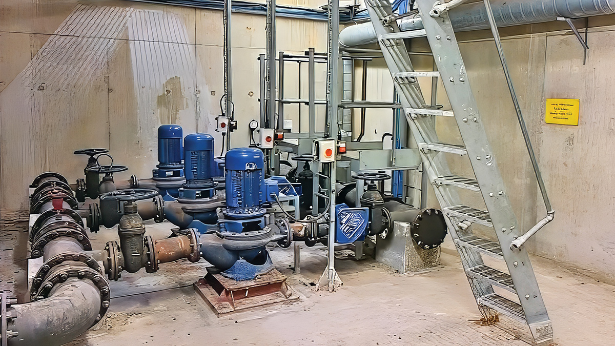
The existing Bearwood WBS – Courtesy of Ward & Burke
Solution overview
The existing installation at Bearwood comprised three 18.5 kW pumps, capable of delivering approximately 86 l/s to the network while sustaining a target pressure of approximately 2.1 bar. The proposed solution comprises four 22.5kW axially split centrifugal pumps in a duty/assist/assist/standby configuration.
An analysis of the existing network by Hydraulic Analysis Ltd outlined the requirement for a 50m3 discharge surge vessel to protect the network. This was to be served by two compressors in a duty/standby configuration, housed within a GRP kiosk.
A new MCC from Ward & Burke supplies power and control for the site, while a new standby generator and dedicated double skin fuel tank provided backup power for the site. Building ventilation works and a new access staircase and gantry arrangement were prescribed to improve operability of the pump station.
Replacing the existing assets raised major risks around the operation of the pumping station and the direct impact any downtime or failures would have on customers. The solution therefore needed to allow for the required redundancy for the site assets and overall system, ensuring that power supply and pump operation had sufficient redundancy and automatic control in the case of any failures.
Visibility and feedback of the site on regional site SCADA for both existing and new assets also added another layer of protection for site operations should any failures occur, meaning they could be addressed promptly.
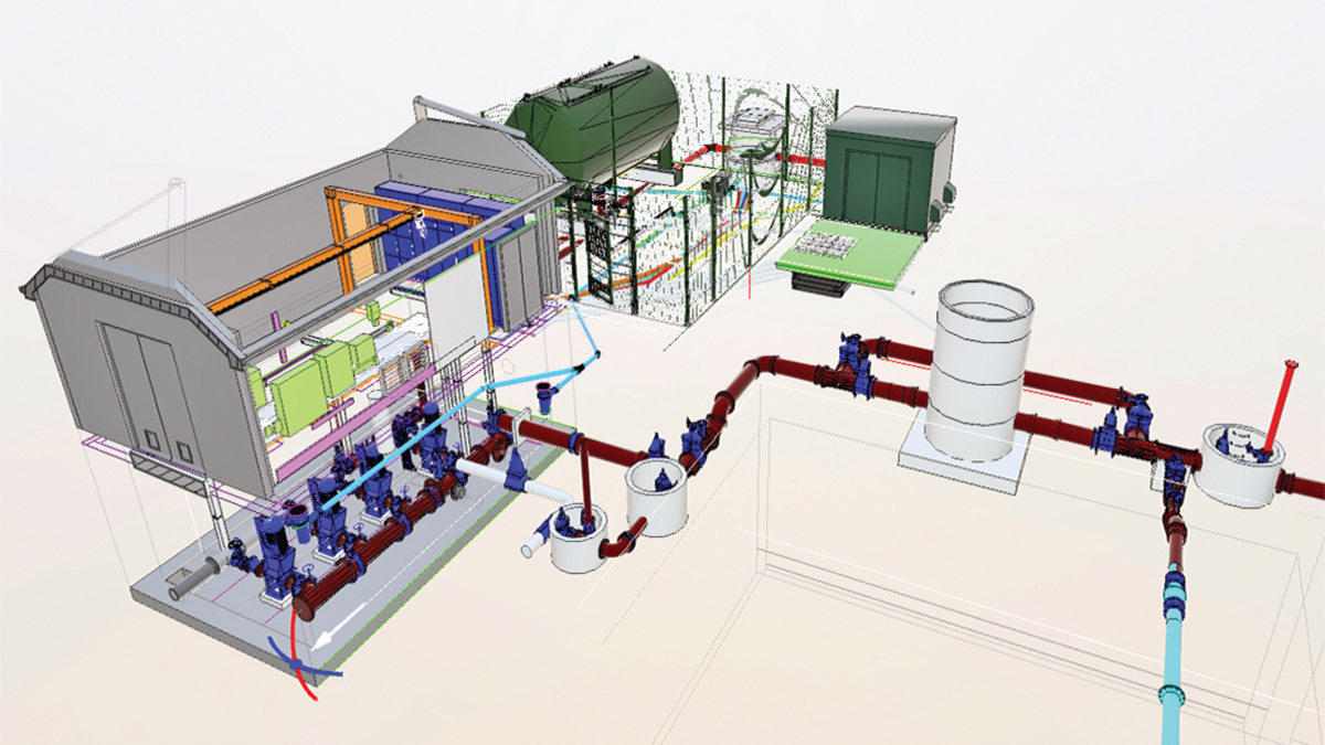
Model of Bearwood WBS and the proposed solution overview – Courtesy of Ward & Burke
Construction sequence & changeover methodology
Works commenced in November 2025 with initial enabling works. This started with the installation of the temporary site backup generator, which allowed for the existing defunct diesel generator to be removed from the WBS building and the accompanying external fuel tank to be removed from the rear of the building.
These works freed up much-needed space both inside and outside the WBS, without reducing the site’s redundancy with respect to power supply. Further enabling works included removal of the internal wall of the WBS which previously divided the generator from the main room.
Removal of the precast ceiling in the generator room was identified in the project’s Design Risk Assessment as a high-risk activity, and as such, solutions were sought to remove the risks associated with its removal, while still allowing the block wall dividing the building to be removed. The solution combined support steelwork for the slabs with the new gantry crane structure. Installing the gantry crane early also reduced the risks associated with movement of materials to/from the basement level later in the project. With the wall removed, the electrical installation for the new MCC could begin.
Concurrently, works began outside at the rear of the WBS. A new discharge main from the WBS was installed, and with this in place, other civils work could be completed including ducting, drainage and slab construction for a surge vessel, compressor kiosk, standby generator and fuel tank. The arrangement for the surge vessel from Quantum Engineering Developments Ltd and future discharge pipework included double isolation valves and washouts for future surge vessel inspection access and commissioning.
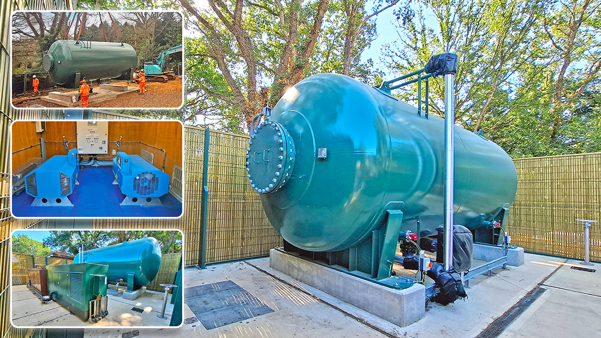
Surge vessel, compressors, standby generator & fuel tank – Courtesy of Ward & Burke
Bearwood WBS & Reservoir: Supply chain – key participants
- Main designer & contractor: Ward & Burke
- GPR & topo survey: Brunel Surveys Ltd
- Hydraulic analysis: Hydraulic Analysis Limited
- HAZOP & ALM studies: Streamflow Engineering
- Directional drilling: Pipeline Services Ltd
- Electrical installation: LDC Electrics
- Systems integration: Bilfinger UK
- MCC: Ward & Burke
- Kiosk: Morgan Marine Ltd
- Excavation supports: MGF Ltd
- Surge vessels: Quantum Engineering Developments Ltd
- Underpressure tapping & in-line valves: R2M Limited
- Pipework: SC Pipelines
- Pipework: Electrosteel Castings (UK) Ltd
- Pipework: Saint Gobain PAM UK
- Stainless steel pipework: Utiliqo Ltd
- Fabricated steel pipework: Freeflow Pipesystems
- Fabricated steel pipework: PMJ Mechanical Ltd
- Pipework fittings: Frazer Utilities
- PE pipework: Aliaxis
- Pipework disinfection: WSM Associates Ltd
- Testing equipment: VP Stopper Specialist
- Pumps: KSB Limited
- Valves: AVK UK Ltd
- Gantry crane: Bramley Engineering (Lifting Gear) Ltd
- Pressure & flow instruments: ABB
- Pressure switches: IFM Electronics
- Ventilation systems: Air Technology Systems
- Standby generator & fuel tank: DTGen
- Concrete coring: Kilnbridge
- Access metalwork: Tushingham Steel Fabricators Ltd
- Access covers & doors: Technocover Ltd
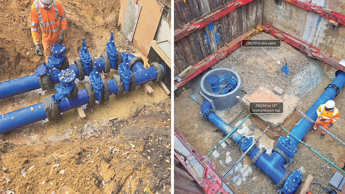
(left) Surge vessel and future discharge main pipework arrangement and (right) the installed cross connection between the new and old outlets – Courtesy of Ward & Burke
Reservoir to booster station pipework
Due to the future flow demand, the existing outlet pipework from the reservoir to the booster pumps would fall outside the allowable velocities and therefore required upsizing. Replacing the existing pipework would require deep excavations (~4m) in a heavily congested area of site with respect to other services, as well as being close to the reservoir and the busy adjacent road.
This would introduce major risks around service strikes, traffic management and disruption to site services which could lead to customer impact.
The solution was to lay a new manifold at the opposite end of the reservoir, with new pipework from each of the three cells. This new manifold would lead into a new main which would feed the booster pumps. This removed the risks associated with traffic management, and significantly reduced the risks associated with service strikes and site operability. A key consideration with these works was that two of the three reservoir cells were in operation at any one time, to ensure no impact to site operation or customer impact.
To ensure the client’s construction assurance, site operations and water quality teams were all aligned with the planned commissioning sequence, a detailed visualisation of the commissioning plan was prepared.
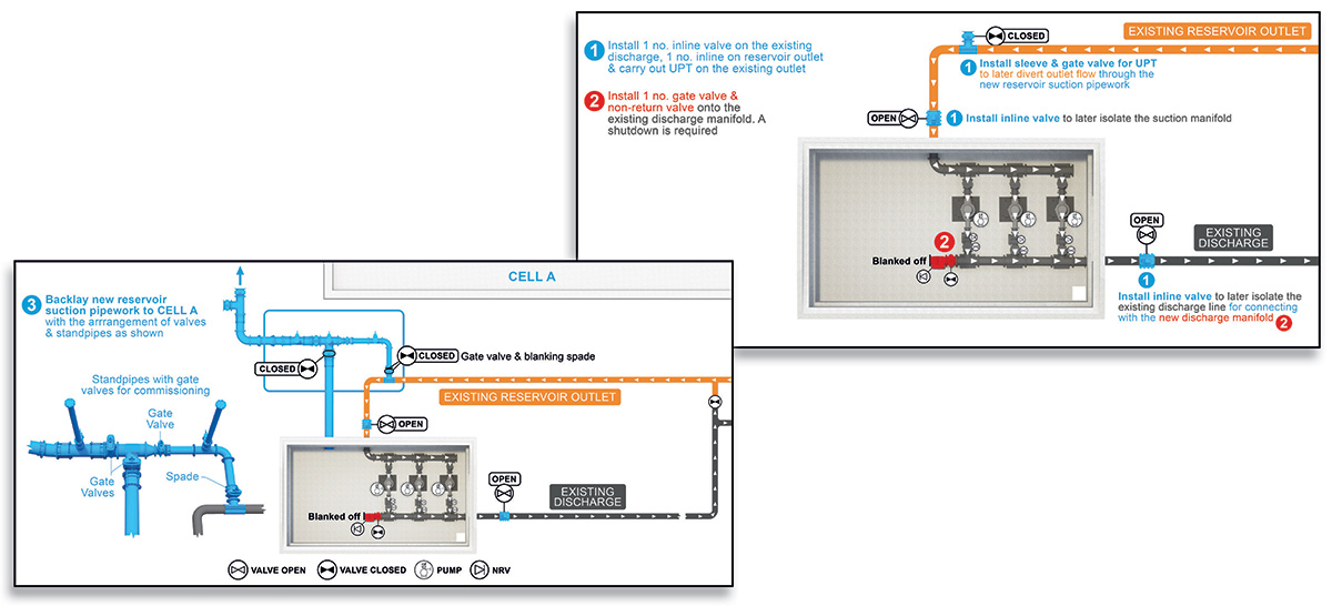
Overview of the cross connection between the new and old outlets – Courtesy of Ward & Burke
As the new manifold would be installed and commissioned in sections, in line with the individual reservoir cell outages, sacrificial commissioning chambers were installed where test spades were required to be removed in the future, greatly reducing the risks associated with working around deep excavations on site. The installation of the cross-connection T and in-line valve on the existing outlet pipework were completed as underpressure connections by R2M Limited; removing the need for a shutdown and the risk of customer impact.
To lay the new pipework into each of the cells, the reservoir walls were cored and a section of pipe cast in. Due to the timings associated with the reservoir works, it was undesirable to rely on a drop test once the cell was recommissioned to determine if the cast in pipe was adequately sealed. If any issues became present, the cell would need to be drained again, works re-completed, and the cell recommissioned before being put back into service, a process which would take up to 2 weeks.
To remove this risk, the cast section was hydrostatically tested externally to the tank, to mimic the hydrostatic pressure of the internal water level. A DN600 pipe spool was bolted to the wall over the cast section and pressure tested, with the seal between the spool flange and the reservoir wall completed using a custom-made gasket. Once the test was passed, the internal reservoir pipework could be installed and external connection to the manifold completed.
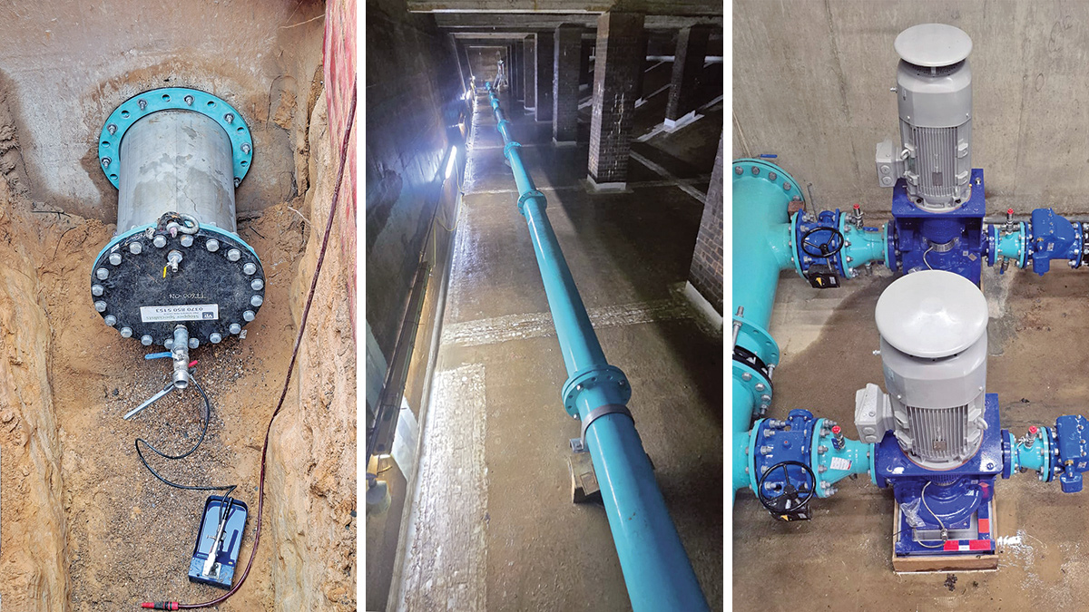
(left) Pressure testing arrangement for testing the newly cast outlets, (middle) the internal pipework installation, and (right) the final two pumps being installed – Courtesy of Ward & Burke
Pump upgrades & discharge main
In parallel to these works, a number of key equipment deliveries were made, including the installation of the new MCC provided by Ward & Burke, as well as the 50m3 surge vessel and associated compressors and kiosk from Morgan Marine Ltd. The delivery of the generator and fuel tank soon followed, meaning the pump upgrade could begin.
To enable the pump upgrade, flushing and commissioning activities for the new reservoir outlet pipework, a single isolation valve had to be fitted in place of a blank plate on the existing live discharge manifold. This would be the only shutdown of the booster station, of just 30 minutes, allowing for contingency. Significant network injection tankering had to be arranged with Site and Network Operations, to enable the shutdown and ensure no impact to the network or customers. With no existing point of isolation on the discharge main, a second in-line valve was installed to establish an isolation point as close to the work area as possible, thereby minimising drain-down times and any shutdown durations.
Once this valve was fitted, the new outlet main and Cell A pipework could be flushed, meaning it could then be commissioned, At the same time, work commenced on the temporary pump arrangement.
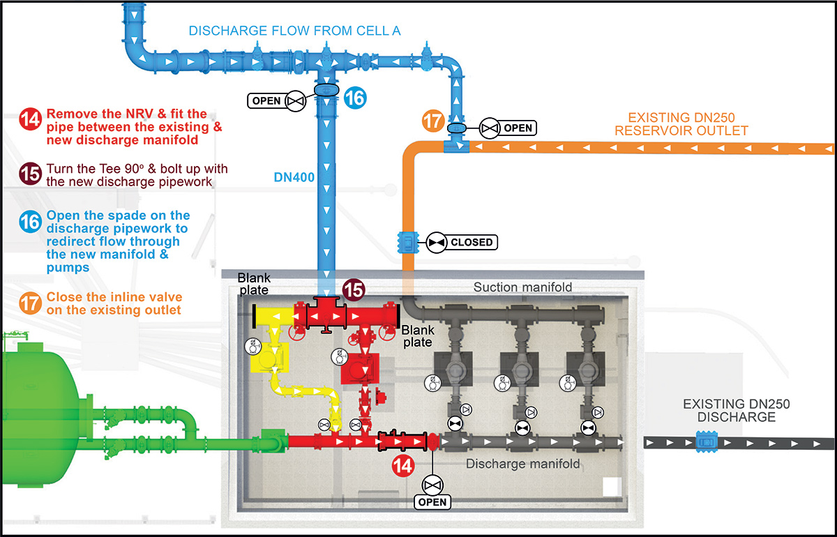
Overview of the temporary pump arrangement alongside the existing pumps – Courtesy of Ward & Burke
Power upgrades for the site were also completed, with the existing 50 kVA supply upgraded to a 140 kVA supply, alongside the installation of a new CT meter. The site was run on the standby generator during these works to remove the need for any shutdown.
The temporary arrangement, which utilises two of the four permanent pumps, can provide the full current customer demand, meaning that once operational, the existing pumps can be removed. The system is powered and controlled by the new MCC and is backed up by the new generator. The surge vessel was also commissioned and put into service at this point, to provide extra protection to the existing network.
Testing & reliability trial period
As part of the wet commissioning of the temporary arrangement and using the washout arrangements upstream of the surge vessel, the pumps were run and used to flush the Cell B pipework. This provided an opportunity to run the pumps with flows prior to going live to the network, while also ensuring the Cell B pipework got a full design flow rate flush.
The temporary arrangement then went through a 14-day reliability period before the existing pumps were removed. During this period, the pump status signals were hard-wired back to the existing panel, so that if one of the new pumpsets was to trip or fail, the existing pumps would start to provide additional support without operator intervention. This also ensured the new pumps were visible on the existing site SCADA, for monitoring by site operations.
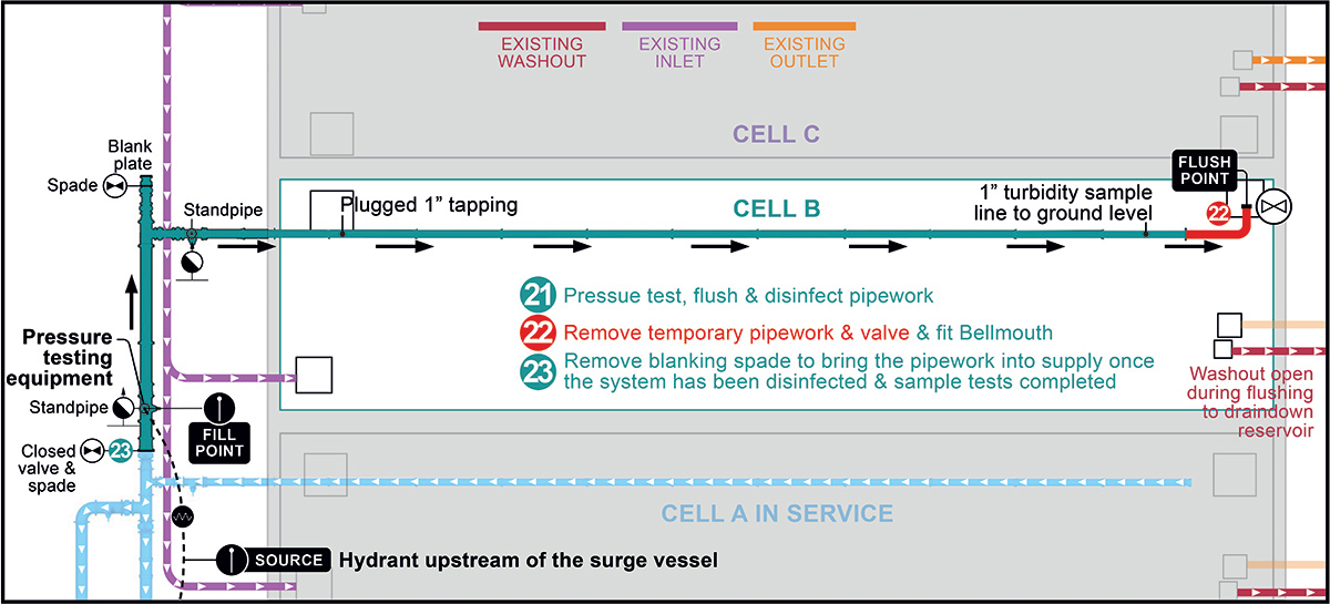
Overview of the flushing arrangement for Cell B – Courtesy of Water & Burke
With the reliability period complete, the remaining existing equipment from the building could be stripped out, including the old pumps, existing MCC, ventilation and any other ancillary equipment. This allowed for the final new pump units to be installed and commissioned, while the Cell C pipework was installed and commissioned also. Once the final two pumps were installed and operational, the first pump installed, which was in the temporary location, could be repositioned to its final permanent position.
New outlet main & final works
The last major element of the scheme was the new outlet main from the booster station. The project driver for this was similar to that of the new reservoir outlet, in that the future flow rate would make the existing outlet main fall foul of pipework velocities.
To avoid modifying the existing pipework, which would disrupt the existing supply to customers, a solution was sought to install a second outlet main to run in parallel with the existing and split the flow rate between the two. This pipeline was to be installed via open cut methodology, but to minimise the impact on neighbouring landowners, the majority of the pipework was installed via horizontal directional drilling (HDD). The final connection to the network trunk main will be completed as part of a separate project.
Finally site fencing, pump cover installation, and floor coating works were undertaken along with final concrete works, site top soiling and planting of fruit trees in line with biodiversity net gain target.
At the time of writing, July 2026, the site is fully operational under Thames Water and final demobilising works alongside handover documentation is being completed, with full handover expected by the end of the month.
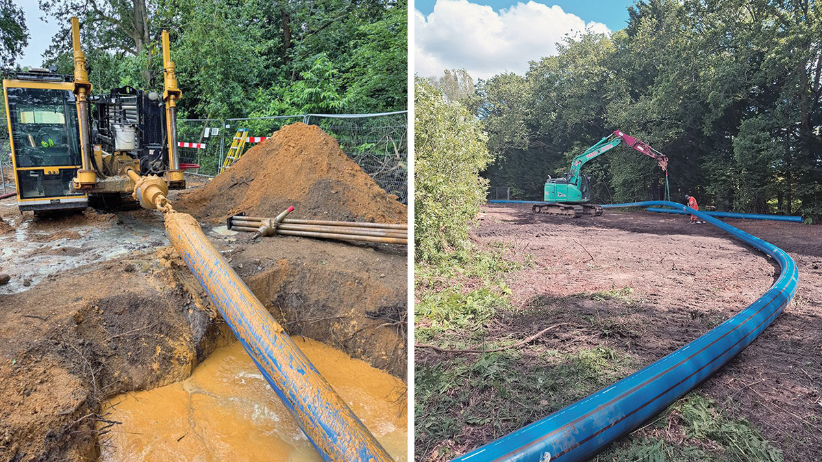
HDD works and pipeline installation - Courtesy of Ward & Burke