
Guildford STW (2026)
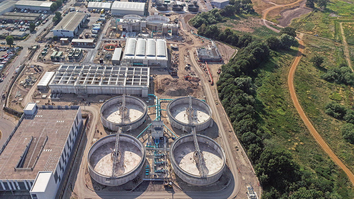
Progress on site (summer 2026) - Courtesy of BAM Enpure JV
The Guildford Sewage Treatment Works (STW) Relocation Project represents a major investment in modern wastewater infrastructure, delivering a sustainable solution that supports future growth while enhancing operational resilience. The project involves relocating the treatment works to create capacity for wider regeneration and development objectives within the Guildford area. Through careful planning, innovative engineering, and close collaboration between project partners, the scheme balances the complex challenges of maintaining wastewater services while constructing new assets and infrastructure. The result will be a modern treatment facility designed to meet current and future environmental standards, improve operational performance, and provide long-term benefits for customers, communities, and the environment.
Previously in Water Projects
Thames Water and BEJV (BAM Enpure Joint Venture) are nearing completion of the construction of the new Guildford STW located on the Slyfield Estate, Guildford. The project has been featured by Water Projects in 2023, 2024 and 2025 and this case study provides a general update on progress and focusses on some of the challenges over the last 12 months. Since the 2025 update, the notable progress on site has been:
- Road construction is 80% complete, all founded above the settlement controlling Load Transfer Platform (LTP).
- All underground civils works have been completed.
- Installation of mechanical equipment is substantially complete across the site.
- Dry commissioning has commenced.
This case study focuses on some of the complicated and unseen civil engineering activities that have been undertaken. The final update in 2027 will focus on the final MEICA and commissioning works.
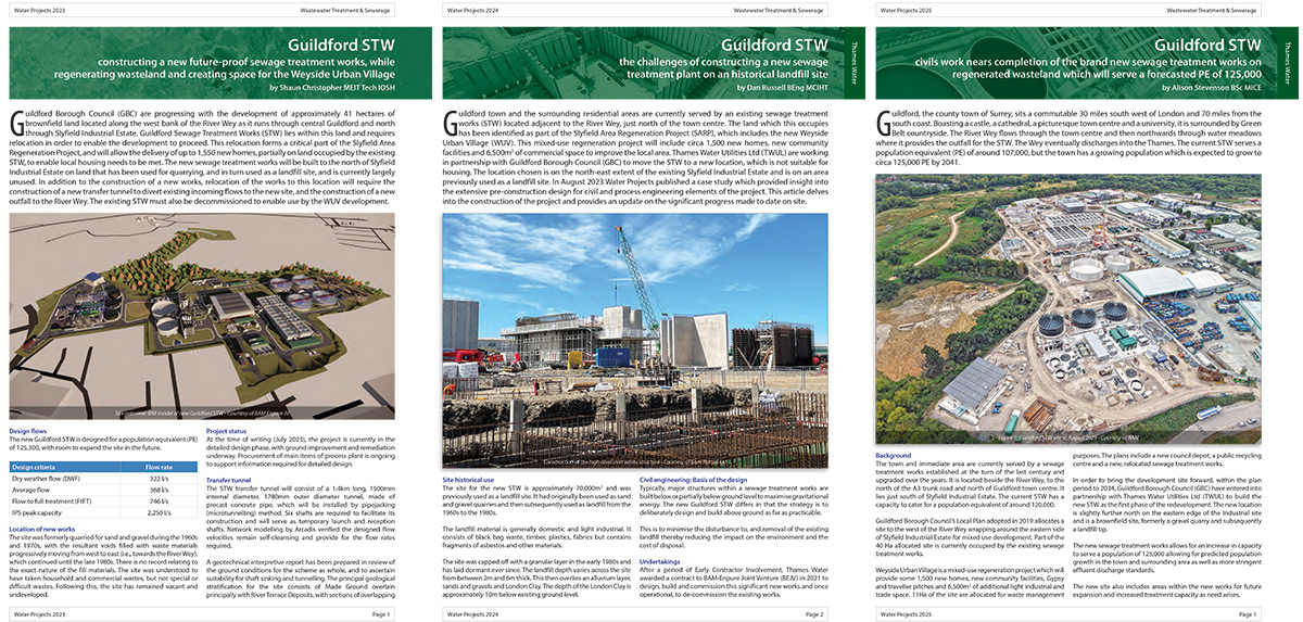
Guildford STW case studies on WaterProjects Online 2023, 2024 and 2025
Underground utilities
To support the new functioning process plant, a total of 9,000m of ductile iron process pipework and 3500m of underground cable trenches have been installed. Whilst the site may be modest in size, installing buried pipes and cabling on a former landfill site and between the 3,500 precast piles has been challenging.
Settlement
All the structures on Guildford have been formed on driven piles to strictly control settlement, as discussed in previous articles. The settlement has been designed to be limited to 15mm for the structures. Similarly, because of the process-critical nature of the pipework and ducting, the settlement of these assets needed to be considered and has been designed to be limited to 50mm.
To manage this, all areas where pipes or ducts are to be installed were supported on capping beams bridging driven piles or in areas of VRI column installations. This method was discussed in the 2025 WaterProjectsOnline case study.
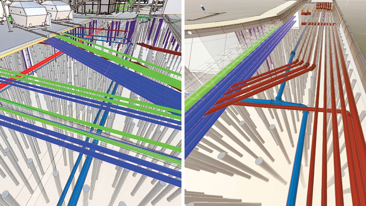
(left) Extract from the federated model showing ducting network adjacent to the inlet works and (right) extract of 3D federated model showing ductile iron pressure pipework, modelled against underground ductwork on an area where VRIs had been installed – Courtesy of BAM Enpure JV
3D model & levels
All of the ducting and pipework has been designed by Arcadis in the federated 3D model. The detailed modelling of utilities was a key project requirement, enabling the successful coordination and integration of all service levels within the overall design.
For the pipework, there is a combination of both gravity and pressure pipelines, with the gravity lines dictating the levels of most of the other apparatus.
As the site is on a former landfill, the ducted network has to contain a sealed and self-contained positive drainage system. It cannot have local soakaways in the draw pits as these could allow ground gas to enter the pits. In this design, any water that accumulates eventually drains back to the inlet pumping station for treatment.
Precast concrete chambers were selected over in situ draw pits. Cast by Poundfield Precast Ltd, each chamber was bespoke to meet the cabling requirements of the ducting network, with spare ducted capacity included as per the specification. Chamber plan dimensions range from 2m x 2m to 3m x 3m, with structures reaching up to 4m high.
The precast chambers were manufactured off site in sections and installed along with a compressible sealing strip detail to prevent any gas ingress. This system offered an advantage in speed of installation over in situ chambers built in large, shored excavations.
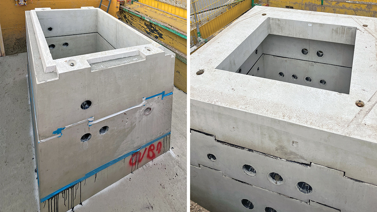
Precast Interlocking reinforced concrete draw pits cast by Poundfield Precast Ltd – Courtesy of BAM Enpure JV
Excavation in a landfill
Key considerations during the construction of the deep trenches within the historic landfill site were minimising off-site disposal and ensuring the safety of the workforce.
As excavated landfill material could not be reused, reducing the volume of material requiring removal from site was a significant project objective. To minimise worker exposure to potentially contaminated ground conditions, all trench excavations were undertaken using shored systems, predominantly trench boxes.
Battered excavations were not utilised, ensuring that excavation works could be carried out safely while maintaining efficient construction progress.
To do this, the following process was adopted:
- Setting out the location of any excavations.
- Ahead of excavating, setting up portable asbestos monitoring equipment to detect airborne fibres.
- Excavating and installing the trench boxes by excavator.
- Installing an additional layer of crushed stone within the excavation to prevent workers from working directly on the landfill.
- Installation of the ducts or pipework within the trench followed by local testing, including air testing and mandrel testing, to verify integrity and compliance with specification.
- Backfilling the trenches.
The deep ducts and pipework on a congested site, combined with all excavations being completed within trench boxes, has meant that production outputs have been more modest on this site than a conventional brownfield site. It is likely that battered excavations would have been quicker, but this would have been at a significant environmental cost in terms of disposal.
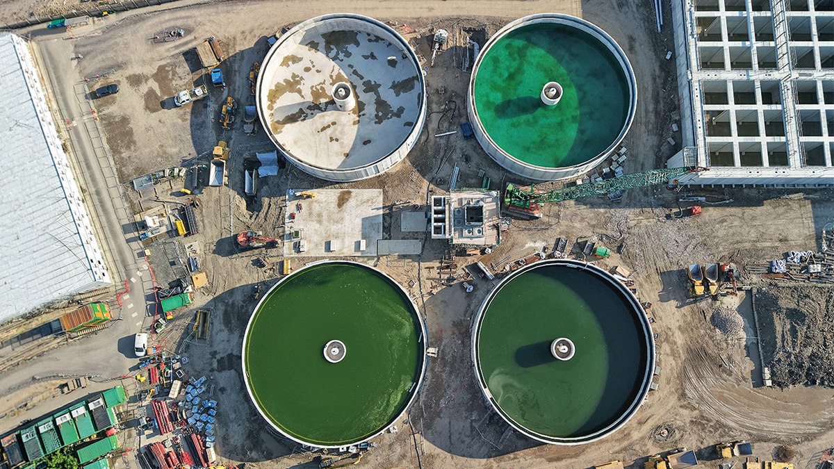
Hydrostatic testing of structures for watertightness underway on three of the A-Consult Ltd FSTs – Courtesy of BAM Enpure JV
Hydrostatic testing
One of the key civils risks identified before commencing works was the risk of leaks on the large concrete tanks during hydrostatic testing. Whilst not a new specification requirement, experience had shown that repairing leaks once filled would be disruptive, so getting it right the first time was of critical importance.
Precast tanks
To maximise programme efficiency and accelerate construction, precast tanks were selected for all major repeatable structures, including the activated sludge plant (ASP), primary settlement tanks (PSTs), final settlement tanks (FSTs), and storm tanks. All structures were founded on reinforced concrete bases supported by driven piles.
Final settlement tanks & storm tanks
The final settlement tanks and storm tanks were designed and installed by A-Consult Ltd.
These structures were constructed using A-Consult’s Aqua-Tank system, in which a series of precast concrete panels are positioned and post-tensioned together to form the tank wall.
The gaps between adjacent panels were sealed vertically using EPDM gaskets, creating a watertight seal once the tank had been aligned and set for circularity. The panels were then cast into a rebated base detail, where the construction joint incorporated both hydrophilic strips and a Cemflex waterbar to provide additional protection against water ingress. Using this system, each tank was fully constructed within one week.
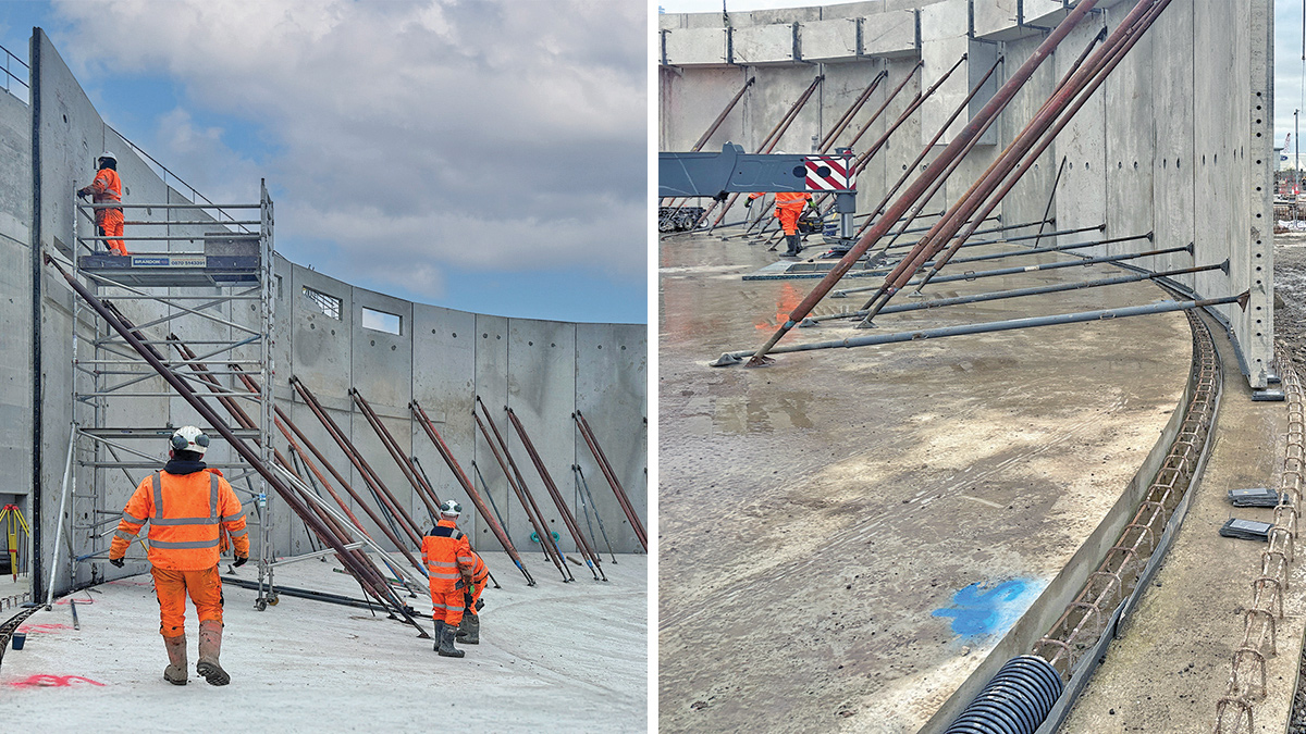
(left) A-Consult Ltd storm tank panels installation and (right) the connection between the precast panels and base installed by A-Consult Ltd – Courtesy of BAM Enpure JV
Primary settlement tanks & activated sludge tanks
The primary settlement tanks and activated sludge tanks were designed by FLI Precast Solutions and installed by DJ Civils Ltd.
These tanks were constructed using the FLI Precast Solutions precast panel system, in which individual panels are connected by reinforced in situ concrete pours. This approach resulted in the highest number of vertical joints among the construction methods used on the project.
To enhance watertightness, the precast panels were manufactured with pre-formed construction joints and integrated hydrophilic strips at all interfaces. These features were installed during manufacture, allowing for faster and more efficient site installation while maintaining the required watertight performance.
Construction joints
In consultation with civils designer, Arcadis, a specific concrete mix was selected for the construction joints on the precast systems.
Whilst both precast systems had in-built construction details as shown above, to de-risk the project further, the project team opted for a mix that was designed in conjunction with specialty chemical company, SIKA. The specifically designed mix was site tested, approved, and used. The admixtures provided reduced permeability and enhanced self-healing properties.
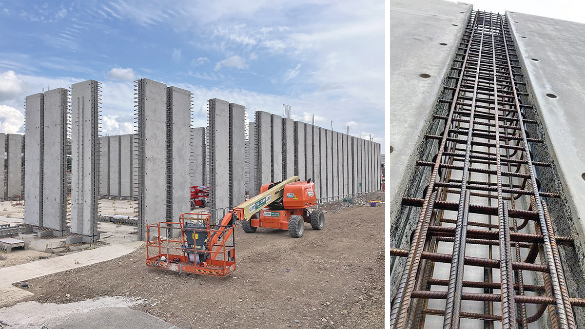
(left) ASP precast walls being erected by FLI Precast Solutions and (right) pre-prepared construction joints with vertical hydrophilic strip – Courtesy of BAM Enpure JV
Water-tightness testing
At the peak of the water testing, 18,000m3 of water was required on-site to test the structures. Initially, it was intended to use final effluent (FE) from the existing treatment works, but with works continuing within the tunnel and reception shaft, transporting FE via the new tunnel was not possible. Transferring the FE overland would have been over 1500m through other active land parcels. As such, the project imported potable water from the local supply.
The import was at a lower rate than initially planned had FE been used; however, the total time for fill and level stabilisation ahead of testing stayed the same, which the project team evidenced through on-site measurement. The testing was undertaken in stages to allow for re-use of the imported water.
All the tanks tested passed the ‘drop test’ for water-tightness, experiencing less than 10mm of drop when compared to a control tank over a seven-day period. This demonstrated that there were no substantial leaks. There is also a requirement for no visible leakage, and with the methods employed, both precast systems performed well, with all joints acting as expected.
Where initial seepage was observed through some of the joints, the engineering team monitored the progression and evidenced that the concrete self-healed over time. No such joints needed to be resin injected.
Once testing was completed, in consultation with the local Environment Agency officer, the project team was able to agree a permit to discharge the imported water to the river whilst controlling PH level and suspended solids.
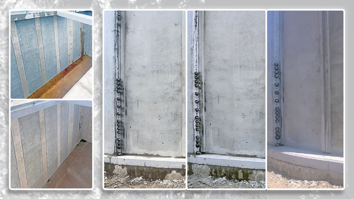
Self-healing of leaks: (left) through concrete stitches in ASP – photos taken one month apart and (right) damp patches on outer face of ring beam seal between the precast panels and the base of the FST – photos taken one month apart – Courtesy of BAM Enpure JV
Guildford STW: Civils works supply chain – key participants
- Main contractor: BAM
- Planning consultant: Adams Hendry Consulting Ltd
- Civil engineering design: Arcadis Group Ltd
- Boreholes & testing: Geo-Environmental Services Ltd
- Asbestos monitoring: Socotec Ltd
- Soil processing: Remediation Waste Management Services
- Gas protection: PAGeo Contracting Ltd
- Rapid impact compaction: Cofra Ltd (Boskalis Group)
- Vertical rigid inclusions: Foundation Piling Ltd
- Concrete piling: Aarsleff Ground Engineering Ltd
- Temporary works specialist: MGF Ltd
- Temporary works specialist: Groundforce
- Temporary works specialist: Mabey Hire Ltd
- Tunnels & shafts: Joseph Gallagher Ltd
- In situ concrete works: Kelly Formwork Ltd
- In situ concrete works: DJ Civils Ltd
- Precast concrete manufacturer: FLI Precast Solutions
- Precast concrete manufacturer: A-Consult Ltd
- Precast concrete manufacturer: Poundfield Precast Ltd
- Concrete supplier: Heidelberg Materials | Brett Group
- Concrete enhancement: SIKA
- Plant hire: Kelleher
- Pipe supplier: Electrosteel Castings (UK) Ltd
- Pipe supplier: Saint Gobain PAM UK
- Gas protection system installation verification: MTS Ltd
Connection to the existing sewer network
To bring the whole project online, the flows from the existing network needed to be intercepted and diverted to the new works. Taking 18 months in the detailed planning, the most complicated of all these connections was made early in 2026. The connection was made whilst keeping the sewer network fully operational.
The existing flows for the Guildford and Burpham catchments all currently enter the inlet pumping station via an old and restricted manhole chamber (MH8201) located adjacent to the existing inlet pumping station. Once complete, all the incoming flows will be intercepted and diverted into the transfer tunnel where they cross it, along its length, rather than all funnelling through one chamber.
Investigations on site while planning the works suggested the chamber was vulnerable, and a series of options were appraised to make the final connection into the network.
After assessing the options, the Thames Water and BEJV project team concluded to hand-drive the last section of the tunnel to the rear of the existing chamber, then construct a temporary shaft over the connection point. This allowed the condition of the existing asset to be properly managed and would also allow a further drop connection to be made vertically above into the transfer tunnel.
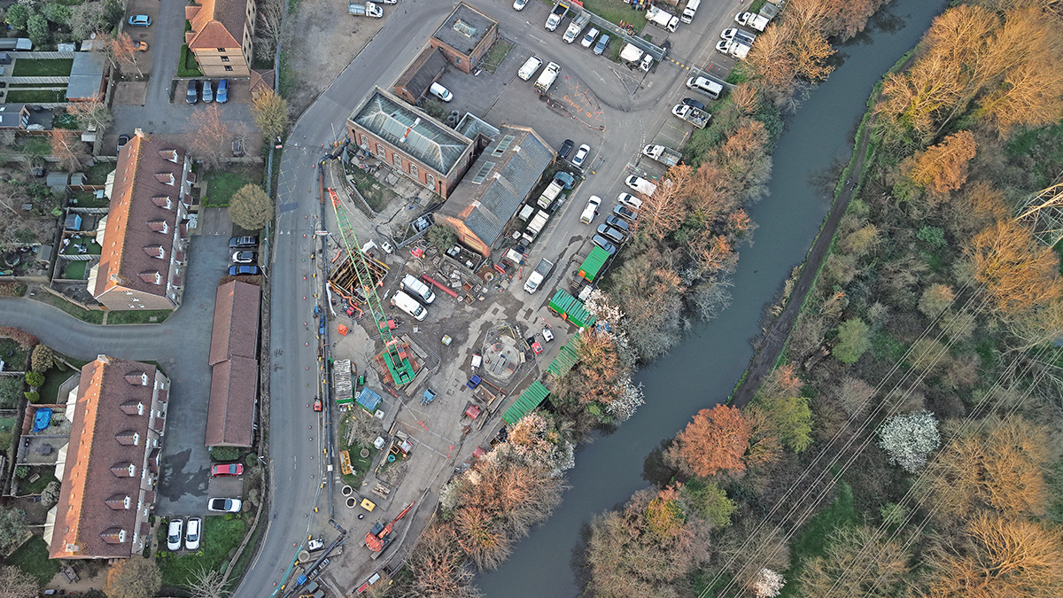
The connection site within the existing works – Courtesy of BAM Enpure JV
Owing to the complexity of making this connection, the project team wanted to complete it before putting the new STW into operation so as not to complicate the commissioning sequence. To enable this, two penstocks were designed into a new downstream shaft, which would allow the team to carry on working in the existing works with the connection already secured ahead of commissioning.
In planning the works, the BEJV/Thames Capital Project team was involved in extensive collaboration with:
- Independent Authorising Body – for permitting to work within the network.
- Thames Operations and Thames Networks to understand the assets, their historical modifications and rehearse the execution of the works including the impact on the existing works.
- An extensive supply chain of specialists to develop a design and method for making the connection.
Temporary works
To enable the works, a 10m deep shaft was excavated adjacent to MH8201. The existing manhole is 2m x 1.4m in plan, but as it is the final chamber before the existing Inlet pumping station, it carries all the sewage flows from the entire Guildford catchment.
As the team was concerned with the stability of the existing asset, specialist temporary works design and associated ground movement analysis was commissioned and carried out by Ayesa and Groundforce. The temporary works solution required ground support from five rows of Groundforce Super-Mega support frames complemented by GU16N sheet piles.
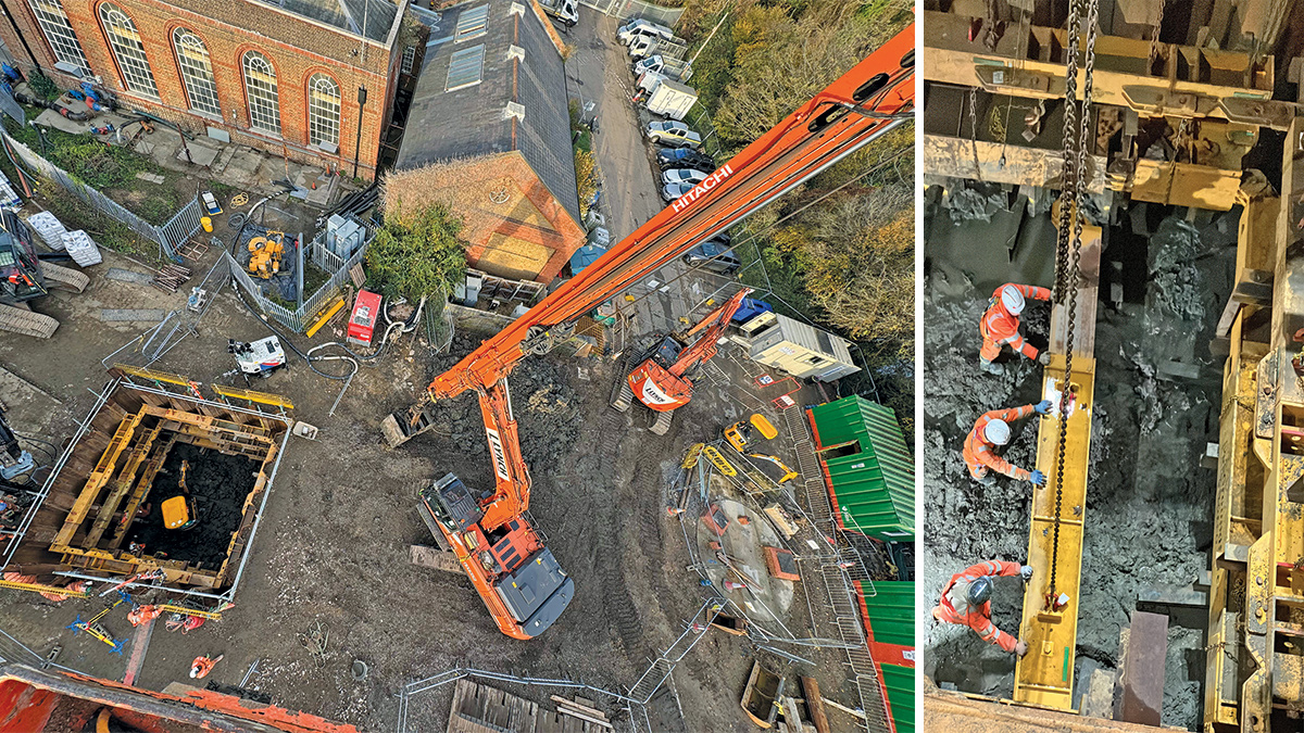
(left) 10m deep shaft excavated by 35T Chameleon and (right) installation of Groundforce Super-Mega braces – Courtesy of BAM Enpure JV
With the works set in a residential area, to minimise noise and vibration, specialist piling advice was sought from an internal BAM team in conjunction with ABI Equipment Ltd and a pre-augured solution was selected, which proved both time-efficient and effective.
The vibration levels on the existing asset were remotely monitored, and the piles were set out precisely using a piling gate.
As the existing chamber was located approximately 1.5m from the temporary works, there was concern that in making the lateral connection to the chamber, this would be through an area of unstable ground, so the area was vertically grouted from the top of the shaft by BAM. A low-strength grout was used to seal up any pores and give stability when mining sideways to install the headworks.
To overcome expected difficulties in excavating the deep shaft between the super mega frames, and with the support of Lynch Plant Hire, a Chameleon vertical excavator was selected, which enabled excavation to the base of the connection shaft. The shaft had been sized to allow excavation down each side of the concrete tunnel using this method.
Once the base was cast, and the dewatering set up and temporary staircase installed, the team removed a section of sheet piles and constructed the Ayesa-designed timber and steel heading, proceeding towards the back of the existing chamber.
Upon uncovering the outside face of the existing chamber, the team observed that the asset was not as expected and part of it required investigation and removal by cutting. By having open cut the excavation for the connection, the team now had the space to investigate this and robustly assess how much of the asset could be removed, in consultation with the structural designer and Client team.

(left) Pumps for MH9501 set below ground level within excavation and (right) suction pipe fixed once stoppers installed during breakthrough works – Courtesy of BAM Enpure JV
Overpumping
To enable the connection into the existing chamber, the existing flows had to be managed. Flows in the network locally meant that an over-pumping scheme needed to be developed, diverting all flows away from MH8201 rather than manage the flows within the chamber using a flume or similar.
This needed to use a combination of diverting flows to both the rear of the inlet pumping station (IPS) and the inlet works, which are approximately 200m apart on the existing Guildford site.
Three pumping systems were needed to achieve this, with interceptions located on the Abbotswood, Burpham and Guildford mains.
The 10m deep sewer and high flows on the Burpham and Guildford Mains meant a solution needed to be developed that would allow suction pumps to be used. The solution was to locally excavate and install temporary works at both MH8202 and MH9501, which allowed the pumps to be positioned at a lower level and reduced the suction head to 5m, meaning they could work effectively.
All pumping installations had standby pumps and generators which were to be used in the event of failure. The pumping systems were sub-contracted to Selwood on a supply and install basis, with the installation taking five weeks including the provision of bespoke temporary works and non-standard flange assemblies to make connections to the existing pumping station.
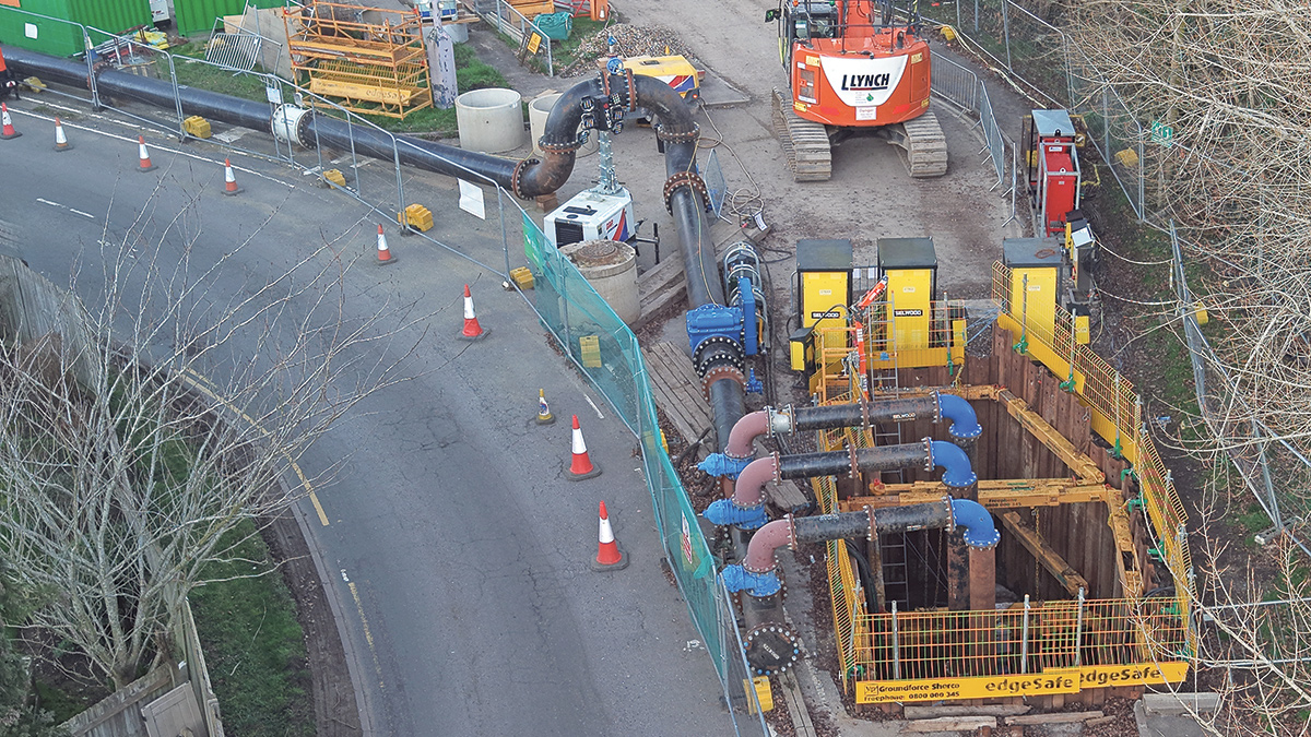
Selwood overpumping set up at MH8202 diverting flows from the Guildford main into the rear of the inlet pump station. The system has a capacity of 600 l/s (duty/assist) with an additional 300l/s (standby) – Courtesy of BAM Enpure JV
Ahead of conducting any permanent works, a full test run of the pumping system was carried out to ensure that everything worked as planned. The test run proved successful, allowing additional isolation valves to be installed at the existing works and surveys to be carried out on parts of the mains that needed verifying. It also allowed the team to access the base of chamber MH8201, and a 3D scan was carried out to assist with the ongoing design.
In total, the project team ended up with five pumped systems in operation, which diverted all sewage entering the existing works. The combined capacity of the temporary systems was 1,200 l/s in duty/assist mode, with an additional 650 l/s reserved for standby only.
For the pumps to work, each chamber where an interception was made needed a head of water building up. To manage this, primary isolation stoppers were installed by OnSite Central at each location, with a secondary stopper as double isolation installed further downstream. These were installed by their confined space entry team when the flows were low enough to access the sewer inverts.
When it came to operating the overpumping, 24-hour monitoring was used. This was a mixture of manual and automated methods. A separate working team was assigned to constantly review stopper pressures at all locations against the design pressures and check that the pumps were running within the stated ranges and flow rates.
Telemetry was installed on the pump installations, which alerted the on-call and management teams of any equipment that was outside of its self-regulated parameters
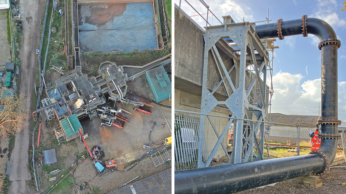
Selwood overpumping set up on MH9501 diverting the Burpham main flows directly to the inlet works. The system has a capacity of 300 l/s (duty/assist) with an additional 300 l/s (standby) – Courtesy of BAM Enpure JV
Breakthrough works
Once all the preparation works were completed, the team monitored the flows in the sewage network. Whilst undertaking the preceding works, the project team had gathered sufficient and detailed knowledge of flow levels in the network and at what times the project team would have to start works.
The pump system was designed to work in relatively dry flows and was not designed to work in storm conditions. What the team also learned was that operationally the works had to start during the low early morning flows (4:00 am), otherwise the flows in the Burpham main would be such that a stopper could not be installed safely. The project team also learned that for this to happen, there needed to be a period of typically 48 hours preceding with no, or very little, rainfall so the system was not surcharged.
Once permitted access was secured into the network, with the overpumping in place, the breakthrough sequence took place. The connection works were executed as planned and comprised:
- Securing the pipework fixing studs to the rear of the chamber.
- Stitch drilling a 1500mm diameter opening into the rear of MH8201.
- Making good the benching to the inside of the chamber for future flows.
- Fixing the steel pipework to the rear of the wall and grouting the annulus between it and the chamber.
- Wire sawing the end of the hand-driven tunnel once the first pipe was fixed.
- Installing the second part of the pipework assembly.
- Securing the pipework against uplift and backfilling with concrete during a 12-hour pour.
- Connecting the vertical backdrop connection.
- Removing the overpumping and returning flows to the existing works.
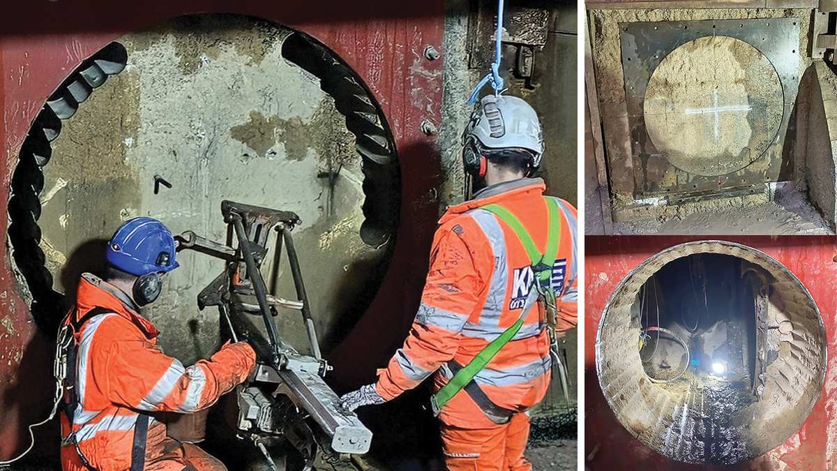
(left) Stitch drilling into existing chamber during breakthrough works and (top right) rear face of the existing chamber with the timber heading completed and the drilling template fixed to the wall, and (bottom right) breakthrough – Courtesy of BAM Enpure JV
In line with Thames Water permitting procedures, once the rear face of the chamber had been drilled, the machinery used was all hydraulically powered rather than 110v supply to remove any ignition concerns. The cutting and coring works were carried out by KM Concrete Cutting Services Ltd using dual coring rigs and a diamond wire saw.
The steel pipework had been designed in two pieces to allow it to be lifted into place, bolted to the pre-prepared wall and secured to the end of the hand-driven tunnel. As the existing chamber was not perpendicular to the hand drive line, a 3° elbow was introduced into the steelwork ahead of its installation.
The breakthrough works were successfully completed in March 2026 over five days without incident and whilst maintaining operational continuity. As soon as the isolations started being removed, the existing works continued accepting flows as normal.
Key to this success was the commitment of the supply chain partners who understood the complexity of the works and were flexible enough to make sure they were available when the flows in the networks were right to allow a start, even when the forecast start date had to change.
- Connection design: Ayesa
- Grouting & stabilisation: BAM
- Temporary works specialist: Groundforce
- Overpumping: Selwood
- Temporary isolations to sewers: OnSite Central
- Piling specialist advisor: ABI Equipment Ltd
- Concrete cutting: KM Concrete Cutting Services Ltd
- Welding: European Active Projects Limited (EAPL)
- Specialist pipe fabrication: JBF Group
- Specialist pipe fabrication: Saint Gobain PAM UK
- Plant hire: Lynch Plant Hire
- Cranage: Hawks Hire
- Concrete supply: Brett Group
The backdrop pipework is now ready to take a new incoming connection, and the new site is now ready to accept the diversion of flows to the new works in 2027.
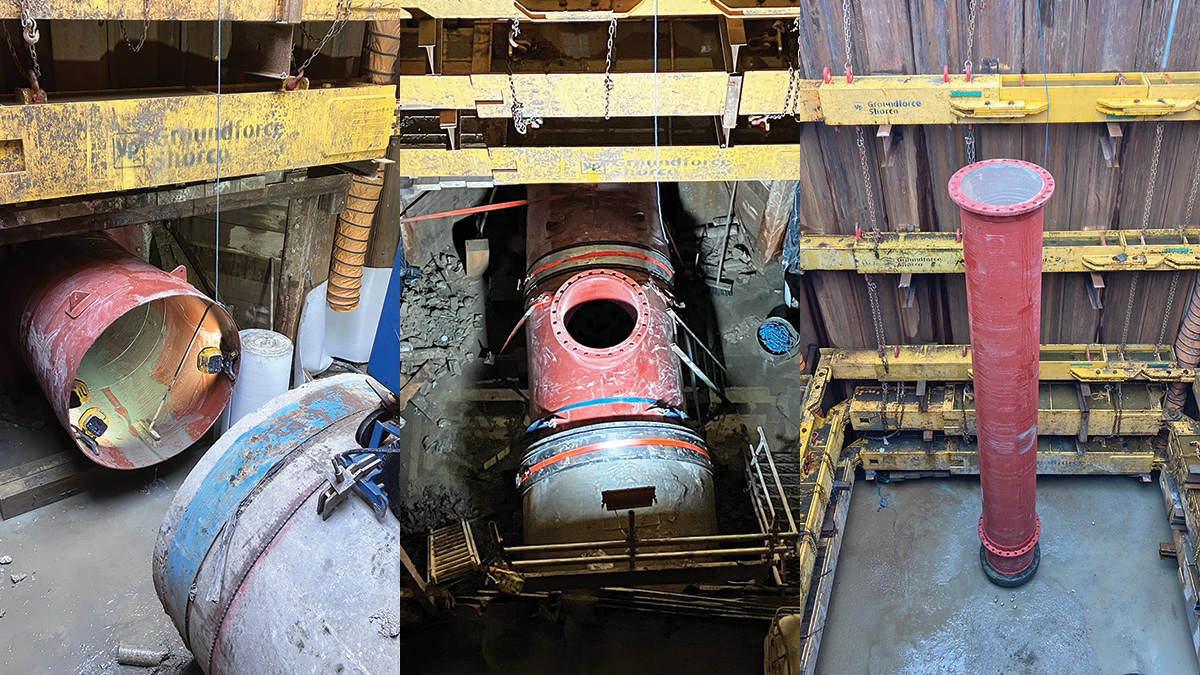
Bespoke pipework installation and concrete surround with backdrop pipework installed – Courtesy of BAM Enpure JV
Looking ahead
Additional live connections to the existing network are planned throughout 2027 ahead of the final diversion of all flows to the new works. While these activities will present their own challenges, none will match the complexity of the connection described above.
Prior to this, with the mechanical and electrical installations nearing completion, the commissioning phase, already underway, will continue through to final completion. This will include the safe ramp-down and decommissioning of the existing works ahead of the site being transformed for its future use.
The 2027 WaterProjectsOnline article will focus on the final stages of the project, covering commissioning, flow transfer activities, and the transition from the existing works to the new facility.
Guildford STW: MEICA works supply chain – key participants
- Main designer/contractor: Enpure Ltd
- CFD analysis: The Fluid Group
- Cake silo: Saxlund International
- PST scrapers & ferric dosing plant: Colloide
- Inlet works & PST odour covers: Power Plastics Ltd
- Grit remover plant: Jacopa
- Escalator screens: Longwood Engineering
- Imported sludge Strainpress: Huber Technology
- Sludge thickening & dewatering: Kent Stainless Ltd
- Odour control plant: Odour Services International Ltd
- FBDA grids & blowers: Xylem Water Solutions
- Cloth pile filters: Eliquo Hydrok Ltd
- Storm tank cleaning system: Sulzer Pumps Wastewater Ltd
- Polymer make-up & dosing plant: Richard Alan Engineering
- Tank logging system: JR Pridham Services Ltd (Unitspark)
- Glass-lined steel tanks: Balmoral Tanks Ltd
- Sludge tank mixing: Landia UK Ltd
- MCCs, PLCs & SCADA: BGEN Ltd
- Kiosks: Qunishield Ltd
- Mechanical installation: FSD Ltd | JBF Group | Fluid Sealing & Engineering (FSE) | HL Engineering
- Access systems: Steelway Fensecure | ANT Access
- Skip trolleys: Serpecon Ltd
- Penstocks, bellmouths & stop logs: Glenfield Invicta Ltd
- Trace heating & lagging: Jade Insulation Ltd
- Standby generators: Dieselec Thistle Generators Ltd