Woolston WwT Scheme – Part 2 (2017)
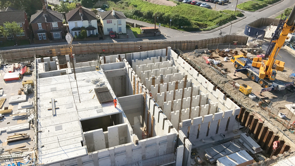
Occupying a site of only 1.26 hectares, this constrained site is surrounded by redevelopment and exisitng housing - Courtesy of 4Delivery
Built in 1966, Southern Water’s Woolston WwTW uses conventional activated sludge plant (ASP) to treat sewage flows from part of the Southampton conurbation, serving a population of approximately 62,000 people. The site occupies an area of 1.26 hectares. The existing sewerage system which feeds into the WwTW collects both wastewater and stormwater from the Woolston catchment. At present treated wastewater is discharged into the River Itchen Estuary through the final effluent outfall. Existing storm and final effluent discharge points will remain unchanged during the works. Construction works are now in the third year on the £63m environmental improvement scheme to redevelop and completely modernise the works.
The second year of the Woolston WwT Scheme was documented in the 2016 edition of UK Water Projects.
Background
4Delivery, a joint venture between Veolia Water Technologies, Costain and MWH Treatment, is undertaking the design and construction of the project on behalf of Southern Water. The permanent works treatment process will treat flows up to 36.9MLD, in compliance with the new discharge permit requirements. All future permanent processes will remain within the boundary of the existing site.
Existing works
The wastewater treatment includes:
- Inlet works comprising:
- Coarse and fine screens and screenings processing.
- Fat, Oil, Grease and Grit, (FOGG) removal and processing.
- High rate primary sedimentation Lamella process.
- Membrane Bio Reactor (MBR) Plant comprising:
- Modified Ludzack Ettinger (MLE) Activated Sludge Plant (ASP) for the biological removal of nitrogen.
- Membrane filtration tank, utilizing microfiltration hollow fiber membranes.
- Existing ASP converted into a storm tank.
- Odour control comprising of chemical scrubbing and carbon units.
The sludge recycling includes:
- Sludge storage and blending
- Indigenous sludge dewatering and processing.
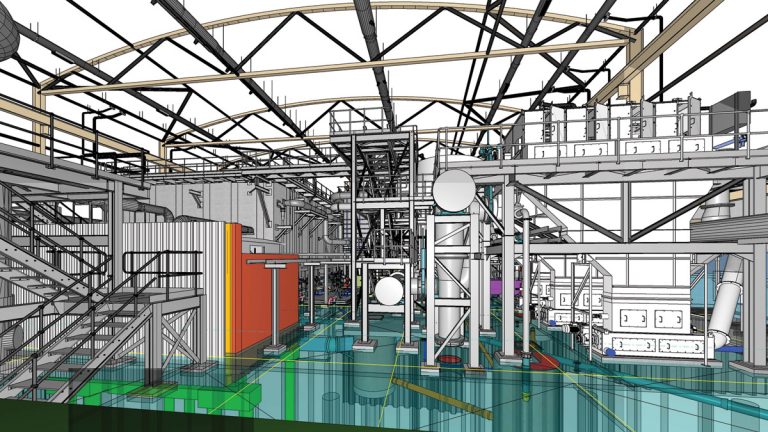
Model image from inside of the primary building – Courtesy of Southern Water
Improvement drivers
The Woolston WwTW discharges into the River Itchen Estuary within the Solent and Southampton water Special Protection Area (SPA) which has been designated as a Nitrate sensitive zone by the Environment Agency. Southern Water is required to provide Nitrogen removal for the Woolston catchment to comply with the European Urban Wastewater Treatment Directive (91/271/EEC) and associated Urban Waste Water Treatment (England and Wales) Regulations 1994 as well as Nitrogen removal requirements under the habitats directive. A new effluent discharge permit requirement of 15mg/l total nitrogen (TN) has been imposed as part of a coordinated strategy involving changes at other WwTWs.
Dispersion modelling predicts that the impact due to odour from the existing WwTW at Woolston is substantial and extensive. Once the installation is completed, with a stack on the primary building for the central odour control facility, all ground level impact remains below the target value of 1.5 ouE/m3 at all locations.
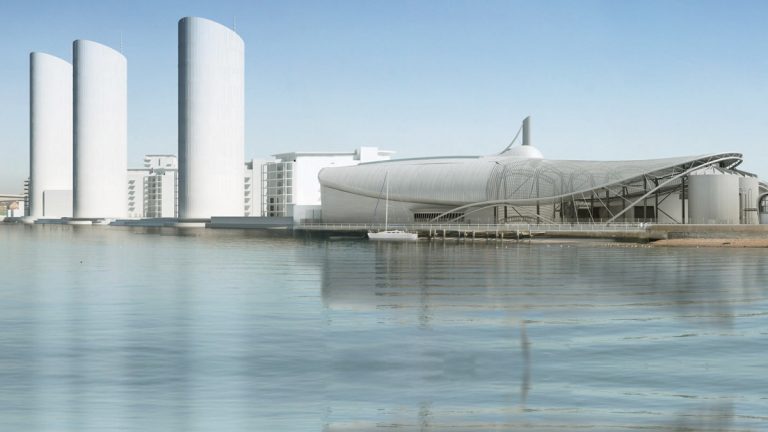
Woolston WwTW visualisation – Courtesy of Southern Water
Enabling works
The Woolston WwTW site is small in size and has a congested layout creating a challenging area in which to construct three large building structures. In order to provide significant programme savings 4Delivery and Southern Water have leased an area of land from a neighbouring development owned by the Homes & Community Agency (HCA). The enabling works have been constructed and were commissioned in December 2015.
These process units provide temporary primary treatment of wastewater, stormwater storage and sludge storage to allow Southern Water to continue to meet their environmental permits whilst construction of the new works, within the extents of the Woolston WwTW site, is completed. Secondary treatment (ASP) within the existing Woolston WwTW site is used to complete the treatment of wastewater whilst the new primary and secondary treatment processes are constructed. Demolition of the existing process units took place in early 2016. At the time of writing (May 2017) the permanent civil works construction is 65% complete and the M&E installation has commenced.
Once the permanent process streams are commissioned, the enabling works primary settlement tanks will be utilised as part of the secondary treatment to allow the existing final settlement tanks to be demolished. This creates the opportunity of constructing the new sludge facilities ahead of the programme.
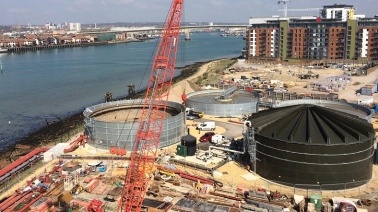
Enabling works construction – Courtesy of Southern Water
Precast installation
Precast construction is being utilised where possible on the scheme to deliver value, reduce duration and improve health and safety. The consented storm overflow (CSO), lamella structure and ASP/membranes tanks are being fabricated, supplied and installed by Carlow Precast (now FLI Precast Solutions).
The design of these structures has been developed specifically to make use of the benefits of precast techniques. These include the ability to have pipe couplings precast into wall units and for complicated hydraulic features to be formed within a factory environment. This enables improved quality to be achieved and avoids some of the risks associated with in situ works.
The precast units arrive on flatbed lorries and are lifted directly into their permanent position using a series of mobile cranes. This avoids the need for storage (space availability is low on site) and double handling. Once placed, the units are joined together by short sections of in situ concrete which then creates a monolithic structure. This method means that large structures can be constructed in far shorter durations compared with entirely in situ approaches. There is also a significantly lower demand for on-site operatives which dramatically improves systems of safe working.
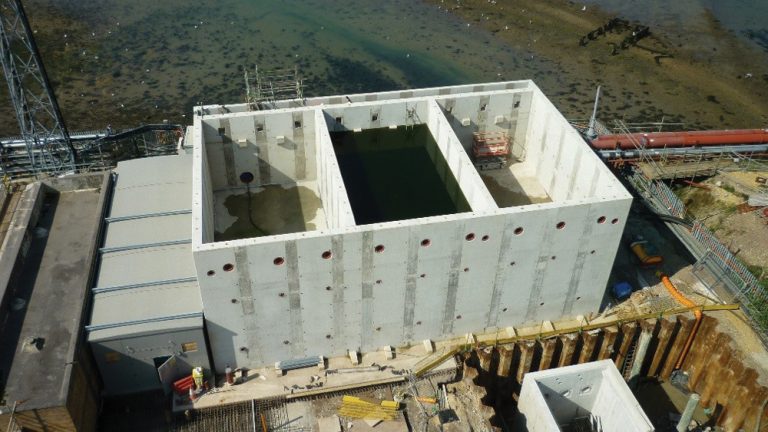
Fully constructed lamella structure – Courtesy of Southern Water
The precast design also considered a number of complex mechanical interfaces and the activities required for their installation. For example, the structure included a number of temporary access ways to facilitate installation of the fine bubble diffused aeration plant. In addition the precast structure also provided plinths with anchor bolts for interfacing with the building superstructure steelwork. These interfaces were managed at design phase by federating supplier models and developing these details accordingly.
Currently (May 2017), the CSO and lamella structures are fully constructed and the ASP/membranes are approximately 80% complete. For completed sections mechanical install is underway and will be part-commissioned in the summer of 2017.
Mechanical fabrication design
Due to the works hydraulic profile, much of the mechanical equipment is significantly elevated above building floor levels. To meet the maintenance requirements of this equipment together with safe access and egress, a complex arrangement of structural steelwork, access platforms, staircases, pipework and cable routing is required.
A detailed and considered approach was required to facilitate the design, incorporating more than 30 (No.) independent 3D mechanical models, numerous steelwork interfaces and a heavily congested floor-level plant layout.
Due to the specific site requirements, the design approach demanded a greater level of definition when compared with less constrained designs that are often passed to the supply chain for development as soon as the access requirements are defined.
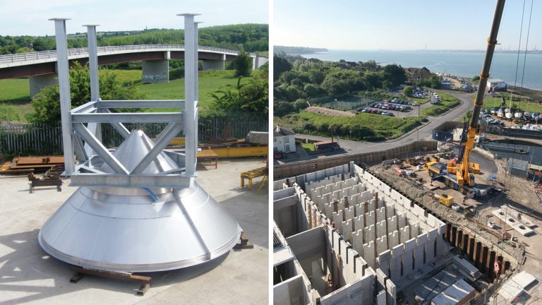
(left) Fabricated stainless steel pipework – Courtesy of Southern Water and (right) Woolston STW under construction – Courtesy of 4Delivery
Management of interfaces throughout the development of the structural steelwork design was key to integrating the mechanical, electrical and civil solutions whilst maintaining sufficient control of the overall design to achieve a harmonised and cost-effective solution.
The design set out to maximise the application of off-site fabrication to reduce on-site personnel, total man hours and high risk construction activities such as welding. This approach took a number of forms, including: incorporating plant onto skid-based designs transportable by lorry; design of steelwork process chambers both in single unit and bolted construction formats; pre-assembled flooring assemblies; welded pipework to flanged termination points. Design of component parts considered interface terminations, installation sequence, size, weight/lifting and component repetition to facilitate the off-site approach.
Off-site inspection and integrity-testing where possible further reduced site-based installation activities. The combination of these methods allowed for safer working conditions to be realised and a significant reduction in the on-site installation programme.
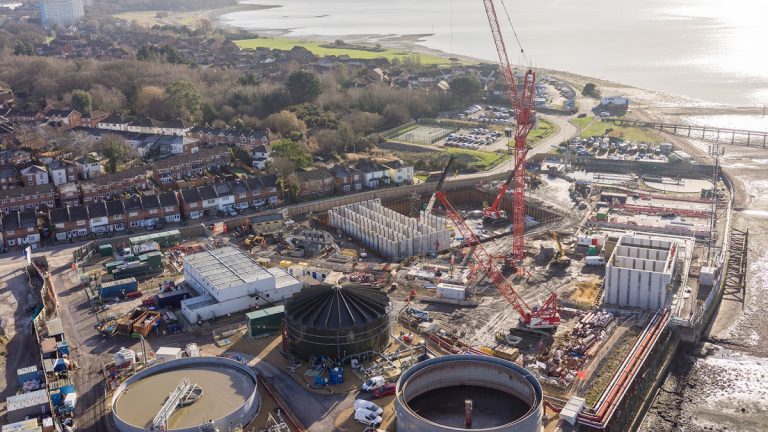
Woolston WwTW under construction – Courtesy of Southern Water
Odour control system
Historically the existing treatment works at Woolston has always suffered with odour issues. The complete redevelopment of the works includes for efficient treatment processes which significantly reduce odours produced. For the odours that are produced these will be treated by a dedicated odour control system supplied by Air Technology Systems (ATS).
Odorous air is drawn from the following process units:
- Inlet works.
- FFT PS.
- FOGG plant.
- Lamellas.
- Ultrafine screens.
- Sludge storage tanks.
- Sludge centrifuge.
- Sealed cake containers.
This odorous air is then passed through a two-stage odour control plant comprising a wet chemical scrubber and carbon filter.
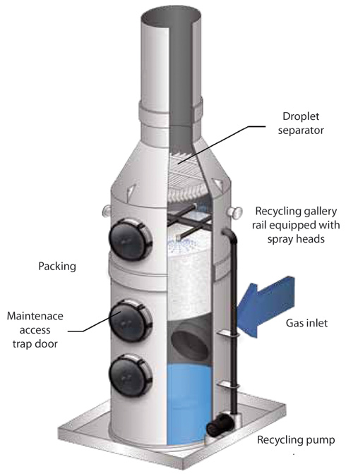
Chemical scrubber unit – Courtesy of ATS (Air Technology Systems)
Odorous air is drawn from both the primary treatment and sludge buildings, this is then treated within the second stage (carbon filter) of the odour control plant. Non odorous air drawn from the secondary process units (ASP and membranes) along with the secondary treatment building is extracted and discharged directly via the stack.
Fresh air is supplied to each building by a dedicated ventilation system. Fresh air is supplied to each MCC kiosk to provide a positive pressure within. Heat is dissipated through louvres and directly extracted from the larger VSD drives and the waste heat re-used by discharging to the building space.
BIM and model interfaces
The use of Building Information Modelling (BIM) on the Woolston project provides a collaborative working environment between all the stakeholders and supply chain employed on the project. The federated model gives a greater understanding by all parties of the design.
To facilitate design development, the 4Delivery design team has created an intelligent 3D model. This provided the ability to ensure that the spatial requirements of the design were met to facilitate efficient construction.
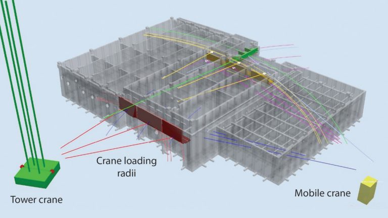
3D model image showing crane radii setting out – Courtesy of Southern Water
The model is being used as a focus of the collaborative solution delivery effort and has produced construction information as well as being an essential aid to plan construction and operational activities. The image below shows how the model has been used to aid setting out crane radii for different loads.
By working with the supply chain in 3D and importing different supplier models into the intelligent 3D model it has proven an effective way of clash checking as well as managing interfaces between different suppliers scopes and civil/mechanical/electrical termination points.


