
Woolston WwT Scheme – Part 1 (2016)
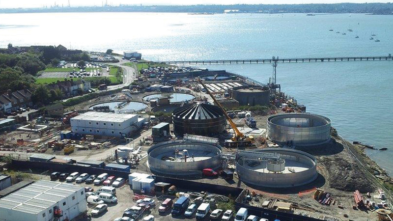
Woolston WwTW - Courtesy of Southern Water
Construction works are now in their second year on Southern Water’s £63 million environmental improvement scheme to redevelop and completely modernise Woolston WwTW. (The first year of the Woolston WwT Scheme was detailed in the 2015 edition of UK Water Projects). The existing works uses a conventional activated sludge plant (ASP), built in 1966, treating sewage flows from part of the Southampton conurbation, serving a population of approximately 62,000 people. The site occupies an area of 1.26 hectares. The existing sewerage system which feeds into the WwTW collects both wastewater and stormwater from the Woolston Catchment area.
Background
Once complete the permanent works treatment process will fully treat flows up to 36.9MLD, in compliance with the new discharge permit requirements. All future permanent processes will remain within the boundary of the existing site.
The wastewater treatment includes the following:
- Inlet works comprising:
- Coarse and fine screens and screenings processing.
- Fat, oil, grease and grit, (FOGG) removal and processing.
- High rate primary sedimentation lamella process.
- Membrane bio-reactor (MBR) plant comprising:
- Modified Ludzack Ettinger (MLE) activated sludge plant (ASP) for the biological removal of nitrogen.
- Membrane filtration tank, utilizing microfiltration hollow fiber membranes.
- Existing ASP converted into future storm tank.
- Odour control comprising of chemical scrubbing and carbon units.
The sludge recycling includes:
- Sludge storage and blending.
- Indigenous sludge dewatering and processing.
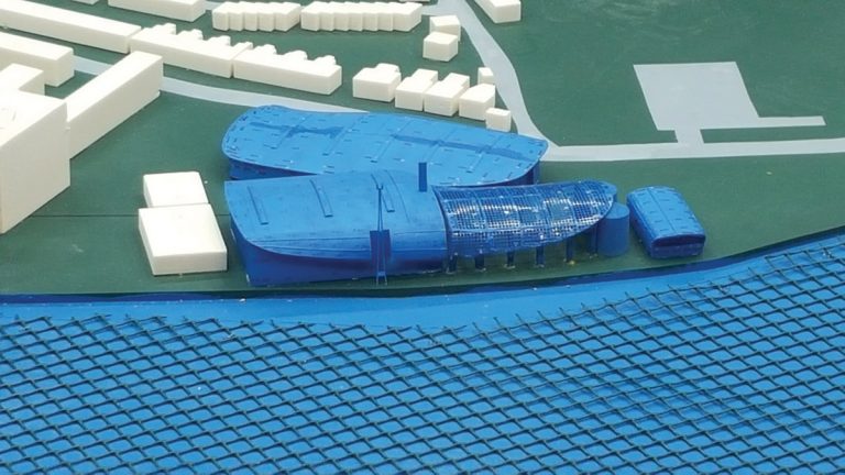
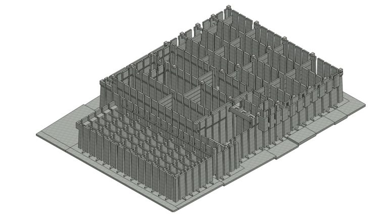
3D printed Woolston WwTW wind tunnel model – Courtesy of 4Delivery
Undertakings
4Delivery, a joint venture between Veolia Water Technologies, Costain and MWH Treatment (now Stantec UK), is undertaking the design and construction of the project on behalf of Southern Water.
Improvement drivers
The Woolston WwTW discharges into the River Itchen Estuary within the Solent and Southampton Water Special Protection Area (SPA) which has been designated as a nitrate sensitive zone by the Environment Agency.
Southern Water is required to provide nitrogen removal for the Woolston catchment to comply with the European Urban Wastewater Treatment Directive (91/271/EEC) and associated Urban Waste Water Treatment (England and Wales) Regulations 1994 as well as nitrogen removal requirements under the habitats directive. A new effluent discharge permit requirement of 15 mg/l total nitrogen (TN) has been imposed as part of a coordinated strategy involving changes at other wastewater treatment works.
Dispersion modelling predicts that the impact due to odour from the existing wastewater treatment works at Woolston is substantial and extensive. Once the installation is completed, with a stack on the primary building for the central odour control facility, all ground level impact remains below the target value of 1.5 ouE/m3 at all locations.
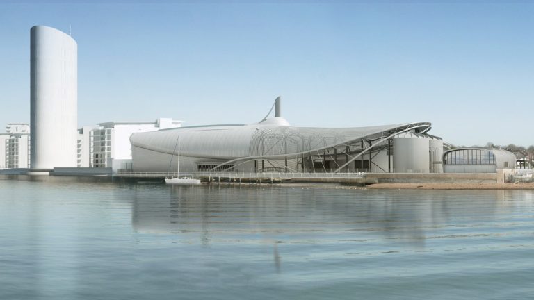
Woolston WwTW visualisation – Courtesy of 4Delivery
Enabling works
The Woolston WwTW site is small and constrained and the new process units and associated buildings will fill the entire site footprint. This has created program, access, logistical and construction challenges for the project.
In order to provide significant programme savings Southern Water has leased an area of land from a neighbouring development owned by the Homes & Community Agency (HCA).
A temporary treatment works known as the enabling works has been constructed on this land and was commissioned in December 2015. The enabling process units comprise, lift pumping station, radial primary settlement tanks (PSTs), stormwater storage and sludge storage to allow Southern Water to continue to meet their environmental permit with the EA whilst construction within the extents of the Woolston WwTW site are completed.
The existing secondary treatment, a carbonaceous activated sludge plant (ASP) and associated final settlement tanks (FSTs) will initially be retained while the new permanent primary and secondary treatment assets are constructed.
Demolition of the redundant process units has now been completed and piling work has commenced. Once the permanent process streams are commissioned, the enabling works PSTs will be temporarily utilised as FSTs to allow the existing FSTs to be demolished. This creates the opportunity of constructing the new sludge facilities ahead of the programme providing an additional saving to the client.
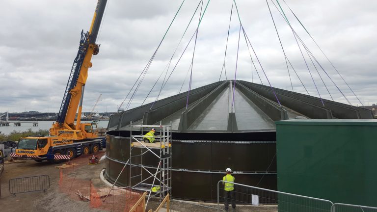
Installation of the enabling sludge tank – Courtesy of 4Delivery
Wind tunnel testing
The three architectural enclosures to be constructed around the process plant have non-regular geometry and curvature to create an interesting visual effect.
For derivation of wind loads, the structural design would normally refer to British Standards or Eurocodes.
However, due to the complex enclosure shapes and their relative positions, conventional analysis would not be able to take account of tunnelling, turbulence and suction effects.
For this reason a wind tunnel study was undertaken by BMT Fluid Mechanics at their testing facility at the National Physics Laboratory. The principle aim was to produce a set of site-specific wind pressures which would input into the structural and cladding design.
4Delivery provided a 3D BIM model of the site and the surrounding area to a radius of 660m. Using 3D-printing techniques, BMT used this data to construct a model of at 1:300 scale to a tolerance of 0.1 mm. The model enclosures were fitted with a total of over 400 surface pressure taps connected to pressure transducers via 1.4 mm tubing and samples were taken at a frequency of five per section.
Baffling and profiled sheeting was used to provide appropriate boundary layer simulation representative of the surrounding topography and the model was rotated to vary the wind direction at the design speed to 21.6m/s.
The model tested two scenarios: with and without the Centenary Quay development to the north of the site to ensure capture of the worst-case effects. The test results were presented in two formats:
- A tabulated set of results showing worst-case magnitudes of net and differential cladding pressures and suctions.
- A rationalised 3D digital model showing the pressures and suctions using a colour contour system.
This data was used to derive wind loads for the structural steelwork design and also for that of the cladding system (e.g. design of fixings and cleats). Use of the test data increased confidence in the design and ensured appropriateness according to actual site conditions.
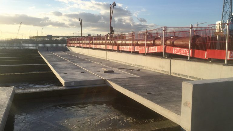
Precast concrete was used to form the storm tank roof slab – Courtesy of 4Delivery
Precast construction
Precast construction is being utilised where possible on the scheme to deliver value and minimise programme risk through reduced time on site. The CSO, inlet channels, lamella structure, activated sludge plant and membrane bio-reactor tanks are all to be provided by Carlow Precast (now FLI Precast Solutions).
Through integrated design, 4Delivery and the supplier were are able to streamline the construction programme, improve build quality and improve safety. All precast structures are designed with mechanical and electrical rebates and fixing details included for seamless integration. At the time of writing (June 2016) the first precast panels are being manufactured and will be installed on site in August, starting with the lamella structure in the primary area.
Carlow Precast panels that form the ASP and MBR structure – Courtesy of 4Delivery
3D model systems and processes
To facilitate design development, the 4Delivery design team have created an intelligent 3D model. This provided the ability to ensure that the spatial requirements of the design were met to facilitate efficient construction.
The model is being used as a focus of the collaborative solution delivery effort and will not only produce construction information but will also be an essential aid to plan construction and operational activities and ensure consistent stakeholder understanding of the project.
Combining the design with an efficient delivery proposition allowed the team to demonstrate value to the client Southern Water, allowing them to award the project to 4Delivery.
The MWH design team have developed a 3D model checking tool which allows the engineers to work within the model environment and decide on the views they want to see, either in a 3D isometric or 2D view, and provide any annotation themselves. Working within the 3D environment, engineers are able to explore, develop and refine the design within a model environment before the production of final drawings. Drawings are produced once and are right first time.
This is a significant step in developing the design process as previously 3D model checking was undertaken by printing out 2D extracts from the model and working on these drawings. This often entails many stages of design development with each stage requiring the production of multiple drawings before the issue of ‘for construction’ information. This is very costly and involves significant time to produce each drawing and only really allows the engineer to check the 2D drawing and not the model.
The model checking tool has been developed within the project without the need for additional funding. Predictions are that on the Woolston project alone there will be savings of approximately 2000 hours of CAD and engineering time.
In addition, the tool enables greater certainty of the quality of the deliverables and so reduces the risk of on-site error and clashes. This provides further savings for the client and 4Delivery through the increased gainshare of the faster, more efficient on site delivery.
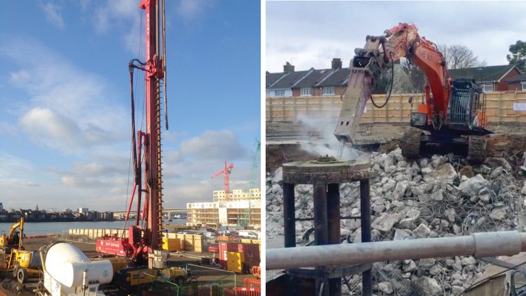
(left) Continuous flight auger piling rig on site and (right) demolition of existing PSTs tanks – Courtesy of 4Delivery
Off-site manufacturing
Due to numerous physical and programme constraints at Woolston WTW, the 4Delivery team are challenging in situ construction practices to deliver large elements of the project using off-site manufacturing techniques. Through early supplier engagement, the team has developed design solutions to suit off-site fabrication.
This has been managed by applying a BIM approach; the team manages supplier data in a shared CDE (common data environment) for 3D model sharing, ensuring governance and version control. This enhances integration between suppliers so that pre-fabricated elements can be delivered to site ‘just-in-time’, avoiding storage and double-handling.
This method of construction will accelerate construction delivery, providing significant programme and cost savings. Off-site manufacturing will reduce project risk by allowing work to be undertaken in controlled settings and more importantly can improve the level of safety on site through reduced risk of working at height, temporary works requirements, lifting operations and plant & vehicle movements.
Programme of work
Following planning permission being granted, Southern Water’s redevelopment of Woolston WwTW started on site in September 2014. The scheduled programme of work is as follows:
- June 2014: Planning permission granted, followed by a six-week standard review period.
- September/October 2014: Mobilisation of welfare units and project offices and construction of temporary treatment works begins on land adjacent to Woolston WwTW.
- Late 2014: Earthworks and piling complete for the temporary treatment works.
- Late 2015: Temporary works complete, allowing the wastewater to be diverted from the existing site.
- Early 2016: Demolition of the existing site begins along with the construction of new site.
- Early 2019: All wastewater is diverted into the new site and the temporary plant is removed and leased land reinstated.
- September 2019: Work complete