Withernsea Long Sea Outfall – Part 1 (2020)
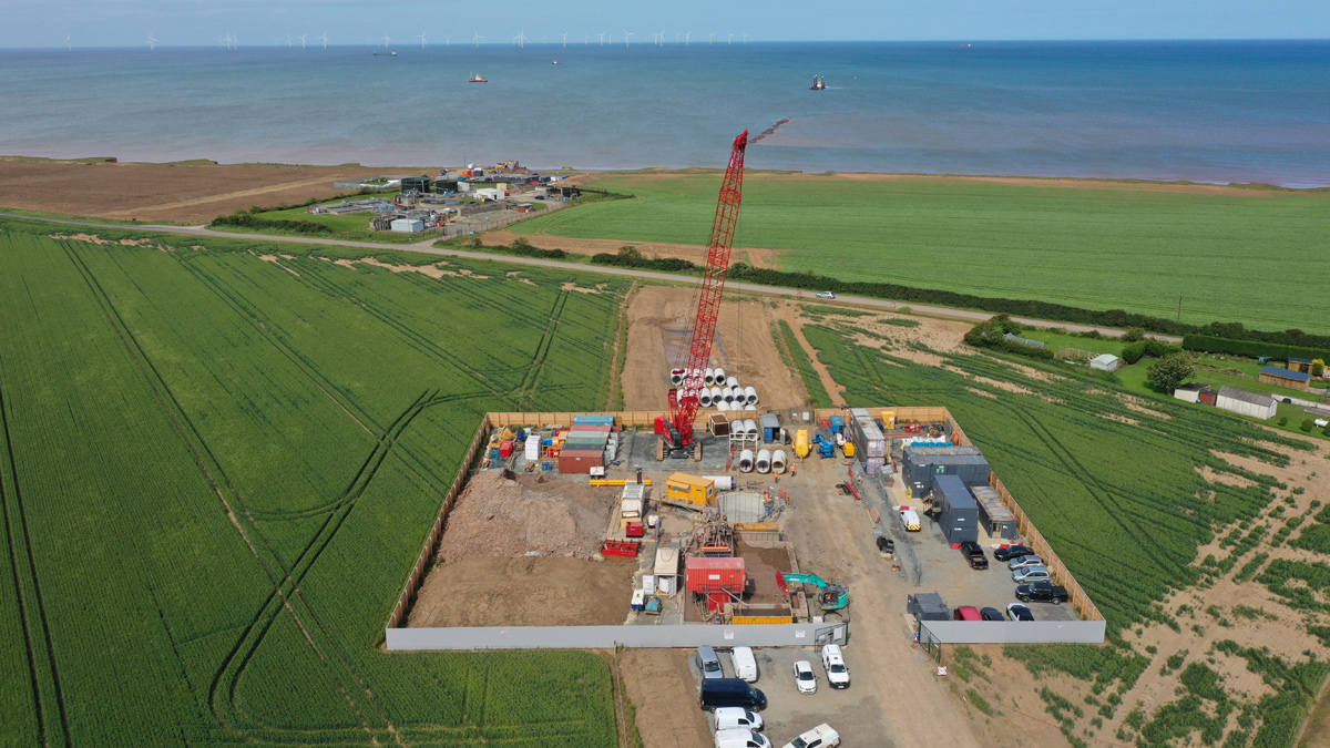
Aerial photo of launch shaft compound - Courtesy of Ward & Burke
Withernsea is located in Yorkshire, approximately 18 miles east of Hull on the Holderness Coast. The area is vulnerable to coastal erosion due to the geology being mainly soft boulder clay. Groynes and sea walls being installed in Bridlington and Hornsea have affected the longshore drift, which has caused Withernsea area beaches to narrow, providing less protection from the waves. East Riding of Yorkshire Council recently installed rock armour on Withernsea beach to help protect the town from coastal erosion after 13m was eroded away in a single week adjacent to Yorkshire Water’s existing Withernsea WwTW in 2015. Withernsea Long Sea Outfall (LSO) is located in Hollym, 4km south of Withernsea. With the cliffs currently eroding away at 7m per year, the WwTW will have to be abandoned in the next 5 to 10 years. Yorkshire Water has taken this opportunity to build a new treatment works 2km inland, extending the existing rising main and creating a new long sea outfall over a kilometre out to sea. Ward & Burke Construction and Van Oord UK Ltd are in a joint venture to deliver this project.
Background
When the previous outfall was constructed in 1991, the WwTW was over 160m from the cliff edge. As of June 2020, coastal erosion has resulted in this distance being reduced to only 40m, and the existing outfall has become exposed on the beach. To proactively relocate the site, Yorkshire Water are investing £26m to build a new treatment works further inland along with a new long sea outfall. The new treatment works will be an ultra-low carbon solution using biological lagoons for the complete treatment process.
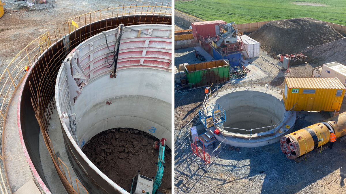
(left) In situ caisson construction and (right) tunnel launch shaft – Courtesy of Ward & Burke
Withernsea LSO: Supply chain – key participants
- Client: Yorkshire Water
- Principal designer: Van Oord/Ward & Burke JV
- Principal contractor: Van Oord/Ward & Burke JV
- Marine contractor: Van Oord
- Tunnelling contractor: Ward and Burke Microtunnelling
- Tunnel boring machine: Herrenknecht International
- Technical documentation: 3rd Light Media
- Electrical contractor: EMCA
- Designer: Mott MacDonald
- Pipe supplier: Pipelife Norge AS
- Concrete pipes: Tracey Concrete
- Gate valves & fittings supplier: Hambaker Pipelines
- Diffuser duckbill valves: MeasurIT Technologies
Caisson construction and microtunnelling
The tunnel is 1500 ID and 462m long from a 13.5m deep launch shaft to a low tide allocation for wet recovery. The shaft consisted of the caisson construction method where the 1m wide caisson walls where poured in 2.5m high sections. Van Oord completed the rest of long sea outfall. During low tide, the TBM recovery position was accessible from the beach, which allowed Ward & Burke to construct a sheet pile arrangement to aid Van Oord in the removal of the TBM.
The tunnel was aligned under a 60-year erosion model so will not be exposed from coastal erosion. Future extension of the tunnel can use the same launch shaft to tunnel away from the cliffs. The wet cast concrete pipes used in this tunnel were made by Tracey Concrete to a Ward & Burke design, 82 (No.) standard pipes, 28 (No.) lubricant jacking pipes and 2 (No.) inter-jacking pipes were used in this tunnel along with the two special end pipes. The inter-jacks were not used in this tunnel as the tunnel was in stiff clay for 25 days and the final jacking friction was 0.5KPa.
The outfall PE pipe from the new WwTW will connect to the LSO in the launch shaft using a converter plate from 450 PE outfall pipe to 1500 concrete tunnel. Both ends of the tunnel were fitted with blank plates whilst the connecting pipework was being done. The tunnelling was undertaken in 24-hour shifts to meet the TBM removal date.
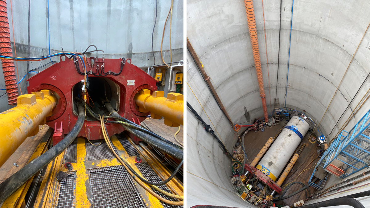
(left) Tunnel jacking frame and (right) view of launch shaft – Courtesy of Ward & Burke
TBM removal
The TBM removal area was coordinated with VanOord to find a suitable place on the beach where both parties could access the area from the beach and the sea. A temporary sheet pile arrangement was designed and built so Van Oord’s Multi Cat would be able to remove the TBM at high tide on the 20 July 2020. Fender piles were put up for the Multi Cat to brace against, as well as sheet piles to tether to. However, due to the large tidal range, Ward & Burke would have a short tidal window to construct the temporary works on the beach. Each day where the tide was low enough, Ward & Burke had about 3-hours of working time. To access the beach a temporary ramp was constructed from the cliff edge, it was mostly made up of 8T rock bags and was covered with compacted earth, it had a line of sheet piles along the side to protect it from the sea, but it was covered with compacted type 1 stones after a few weeks due to the clay washing away.
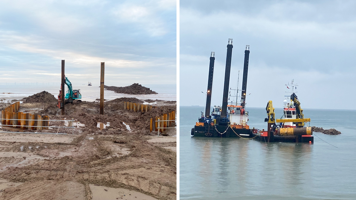
(left) Fender piles installation at reception pit and (right) TBM retrieval – Courtesy of Ward & Burke
New twin pipeline
The rising main coming from Memorial Gardens Pumping Station was extended 2km inland to the new wastewater treatment works. The outfall pipe was laid in the same trench; this will connect the new WwTW with the long sea outfall. Both pipes maintained 300mm gap between them and are 450mm OD SDR17 PE100 pipes with the sections welded together using electrofusion couplings. The pipelines were laid on S1/S2 self-compacting granular backfill, and then covered with 150mm above the pipe, a stone cart was used to backfill the trench. A 1m cover was required for the pipe with exceptions for ditch crossings, where a 0.6m cover was required, only three ditches were crossed.
The grade of the pipeline changes to accommodate the air valves and washouts (ranging between 3.41% and -2.72%). The air valves and washouts were placed as close to the fence as reasonably practicable to not affect the farmer’s fields.
The trench was dug using a tapered bucket (1200mm to 1500mm) to improve the stability of the sides and have a cleaner dig. Where the trench was deeper the sides were stepped as well as banked, this allowed no man access into the trench as the pipe was welded on top. The bucket used was designed to suit this job as this type of bucket works well in stiff clay.
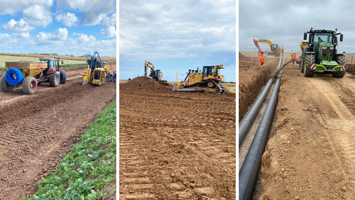
(left) Land drainage installation (centre) land reinstatement and (right) backfilling of pipework – Courtesy of Ward & Burke
The land drains were all diverted pre-construction to avoid flooding fields upstream; the plastic land drains were replaced once the pipe was laid. However, the clay land drains were not able to be replaced therefore a new post-construction land drain will divert the remaining land drains parallel to the pipeline and into to the drainage network. After the pipe was tested and the land drains installed the land was reinstated and returned to the farmers for productive use. The wayleave crossed a public right of way, therefore gates were put in place to prevent the public from accessing the works and a strict closed gate policy was enforced.
This outfall from the WwTW was connected to the LSO in the launch shaft, the pipework was surrounded by concrete manhole rings and filled with shingle, the rest of the shaft was backfilled with soil. The top of the shaft was broken down 1.5m below ground level and covered in topsoil to reinstate the field for productive use.
Marine long sea outfall
The offshore connection consisted of a conventional open cut over the full 1,000m length to a new single riser diffuser location with 4 (No.) non-return valves, scour protection and diffuser protection structure.
As part of the contracted scope of works, Van Oord UK was responsible for the design, procurement, installation, testing and commissioning of the LSO pipeline, except for the basic hydraulic analysis for determination of the pipeline diameter, which was tested and commissioned.
The requirement was for the new LSO to be installed 50m from and parallel to the existing Withernsea LSO, which had to be maintained as operational until the new LSO was fully tested and commissioned.
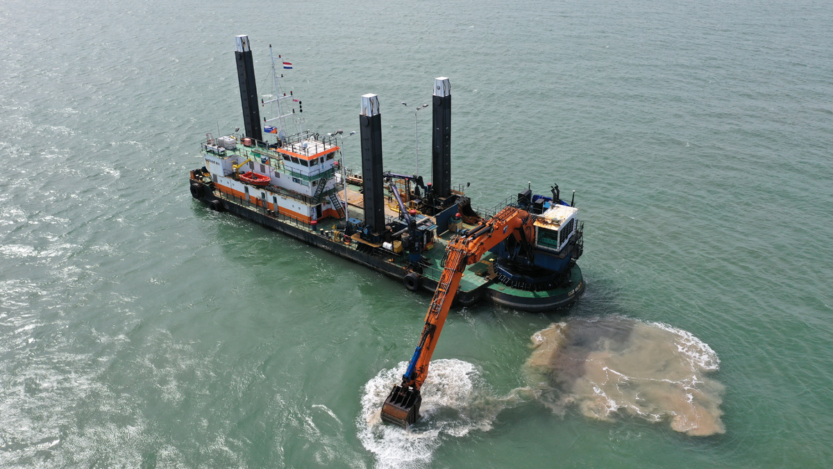
Backhoe dredger Razende Bol operational – Courtesy of Van Oord
Trenching operations
Prior to the commencement of the trenching operations, a hydrographic survey was performed to establish existing seabed levels and provide survey information to the designers for preparation of the final design of the trench, considering a minimum cover from seabed level to the crown of the pipeline of 3m. This was to guarantee that the minimum cover would be achieved for the duration of the design life and took into consideration the predicted changes of the seabed over the design life. A further requirement was for the pipeline to be laid with a negative gradient from the end of the tunnel point up to the diffuser connection location so that over its entire length there would be no fall back.
The excavated material was temporarily stored along the trench alignment prior to its re-use as back fill following installation of the LSO pipelines. Trenching operations were performed by Backhoe dredger Razende Bol, mobilised from The Netherlands to the Port of Grimsby where it was prepared for operations. The vessel began trenching works in early June, completing a volume of approximately 50,000m3 within 4 weeks, and achieving the trench alignment tolerances of vertically +30/-30 cm required for installation of the new LSO.
Pipeline design and installation
The pipeline had to be designed to be stable in the ‘worst case’ design loads for current and wave loading conditions provided. It was therefore necessary to weight the pipeline with concrete collars to provide a specific gravity of not less than 1.35 that could be achieved without any reliance on backfill material.
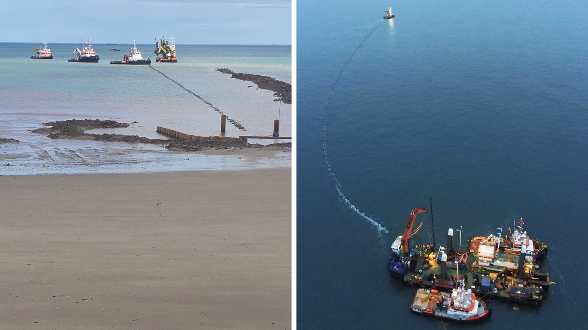
(left) Onshore LSO section installation and (right) commencement of LSO installation – Courtesy of Van Oord
The solid wall polyethylene pipeline was manufactured in Norway by Pipelife Norge AS, a framework supplier to Yorkshire Water. Van Oord was responsible for determining the appropriate SDR with consideration of installation stresses and associated risk during marine operations. This was established as SDR 17 as opposed to the minimum SDR of 26 determined by the client. The number of joints in the PE pipeline was reduced to the bare minimum.
The pipeline sections were towed from Norway in 4 x 250m lengths. The Alexandra Dock on the River Humber had been selected for the final preparations of the pipeline, where the concrete collars were fitted at 4m intervals along the pipeline. On completion, the 250 sections were towed to sheltered anchorage on the River Humber where the sections were welded into 2 x 500m lengths. During a good weather window of 4 days, these pipelines were towed to the Withernsea site location. Following a meticulously planned ‘route-installation-procedure’, both 500m lengths were installed within a period of 3 days and were subjected to the contractually required pressure tests before sign-off from the client. The number of in situ joints was reduced to one, in line with the client’s requirement.
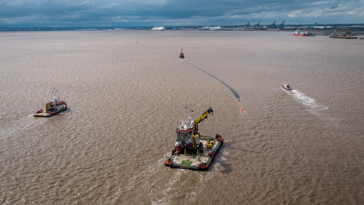
LSO pipeline sections arrive from Norway – Courtesy of Van Oord
Diffuser installation
Completion of the diffuser pipe section immediately followed successful installation of the LSO lengths. This was considered a potentially high-risk activity and the backhoe dredger Razende Bol was converted to guarantee a stable, safe diving platform from which to operate. The diving operations were performed during the slack tide periods and involved stabilising the single diffuser pipe section and installing the diffuser head, which consisted of four Tideflex duckbill valves . As these works progressed, clay backfilling was undertaken, followed by construction of a rock scour blanket consisting of a filter and rock armour layer. When the top level of the filter layer was reached, a diffuser protection frame was installed. The required volume of filter and rock armour was delivered alongside the Razende Bol on board a flat-top barge prepared for offshore operations.
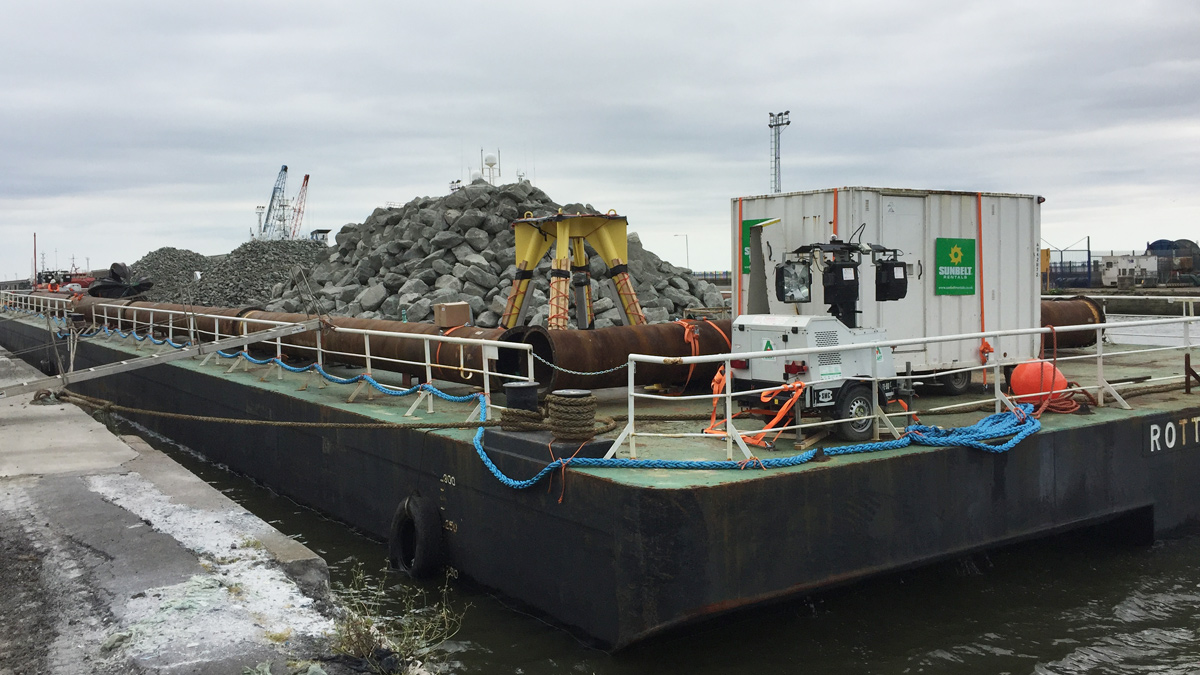
Offshore rock transport barge loaded – Courtesy of Van Oord
Trench backfilling
The placing of the side-cast excavated trench materials had to be carefully controlled to avoid disturbing or damaging the outfall pipeline as it was being installed. During the entire backfilling operations, daily hydrographic surveys were performed to monitor the gradual filling of the trench up to the final level of the existing seabed. In line with specification and regulatory requirements, the seabed was restored to its original levels (+/- 0.5m).
Tunnel – LSO connection
During the backfilling operations of the main length of the trench, the LSO pipe section (installed by float and flood method) had to be connected to the tunnel section. A sheetpile support construction was installed on the beach section to provide a safe working environment between the tunnel end and LSO section of the pipeline. A steel bulkhead plate was welded onto the tunnel section. The LSO was then connected via an accurately measured length of HDPE pipeline, using a flange-to-flange connection. These final operations had to be performed within a short time frame, within the low water tidal range.
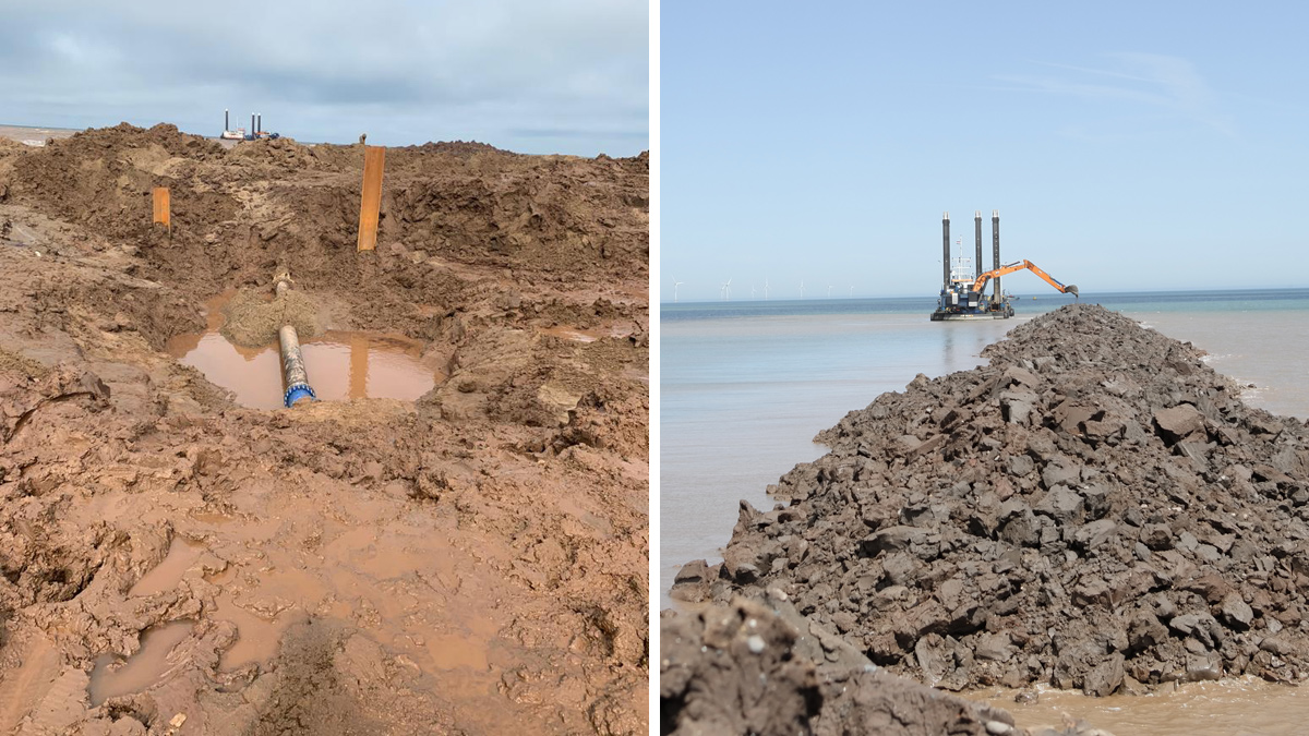
(left) Spool piece between tunnel and LSO and (right) backhoe dredger Razende Bol backfilling of trench – Courtesy of Van Oord
Commissioning and final handover
Upon completion of the installation of the marine section of the LSO by float and flood method, the full 1.5 km length was pressure tested. A diver video survey of the diffuser/duckbill valves in operation formed part of the procedure but had to be performed at the final completion of the works. Following the submission of all required and described surveys and back up documentation, both contractors handed over the combined sections of works to Yorkshire Water. The project, executed in a period of intense scrutiny due to COVID-19, delivered all the client’s requirements and was completed safely, accurately and on schedule.


