
Ards North Wastewater Improvement Scheme (2023)
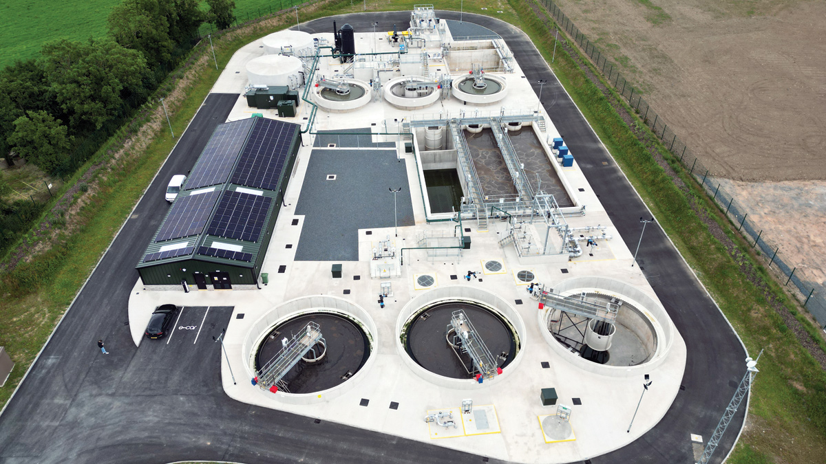
Ards North WwTW - Courtesy of NI Water
The Ards Peninsula is a scenic area in County Down, situated on the north-east coast of Northern Ireland. It separates Strangford Lough from the north channel of the Irish Sea and its coastal towns and villages are popular with day trippers and caravanners alike. By 2020, the wastewater treatment works serving the villages of Carrowdore and Ballywalter were operating at full capacity. NI Water investment was required to ensure that these areas could meet future EU and Northern Ireland Environment Agency (NIEA) standards. The area of Ballywhiskin only had primary settlement, which was not deemed sufficient, and the caravan parks and small settlements in the Ballywalter area were served by septic tanks, which again only offered primary settlement of wastewater before discharge to nearby watercourses. The beaches in the area represent significant tourist amenity and an extensive treatment scheme was essential to meet future bathing water quality standards in line with NIEA standards.
What the scheme involved
The two-year Ards North Wastewater Improvement Scheme involved the rationalisation of the Carrowdore, Ballywhiskin and Ballywalter catchments so that all wastewater flows from these areas could be transferred to a new state-of-the-art wastewater treatment works (WwTW) constructed on a greenfield site off the Ganaway Road in Ballywalter.
In addition to these catchments, the new treatment works has been designed to treat wastewater flows from nearby caravan parks and small settlements, which previously had no treatment facilities.
The scheme was split into two contracts; one for the design and construction of new pumping stations, pipelines and a modern wastewater treatment works, which was awarded to BSG Civil Engineering, and another for the design and installation of a new long sea outfall, which was awarded to Farrans. Project management/technical support for both contracts was provided by Tetra Tech.
This article focuses on the work carried out to construct the new WwTW, pumping stations and pipelines by BSG Civil Engineering to serve the combined catchments and cope with seasonal fluctuations in population to protect the tourism potential of the area for many years to come.
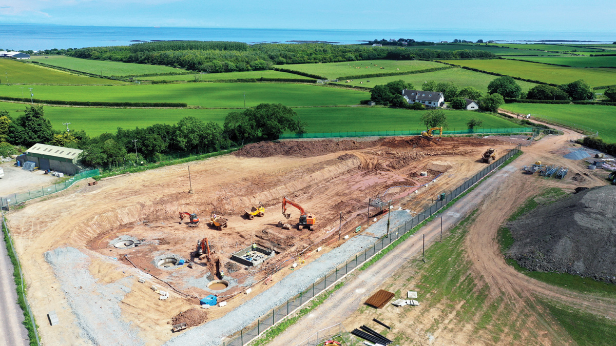
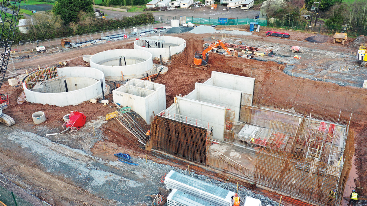
Bulk excavation – Courtesy of BSG Civil Engineering Ltd
Early contractor involvement/design and build contract
BSG Civil Engineering was appointed by NI Water as the main contractor in November 2018 under an NEC 3 Early Contractor Involvement (ECI) contract. BSG provided multi-disciplinary design, project and supply chain management and all civil engineering, process and MIECA works for the contract from start to completion. The ECI phase allowed BSG to align resources and integrate objectives with NI Water and their project management team from Tetra Tech at an early stage to benefit delivery. This proactive approach led to enhanced collaboration, innovation, value, efficiency and reduced whole life costs for the project.
Primary drivers
The purpose and drivers for this project were as follows:
- Achieve compliance with current and future EU directives on effluent discharge standards.
- Meet Registered Discharge Standards set by the Northern Ireland Environment Agency (NIEA).
- Provide a flexible design to cater for future flows and the significant summer/winter fluctuations.
- Minimise impacts to community and environment.
- Support local development, tourism and economic growth.
- Deliver best value for money construction making use of existing assets.
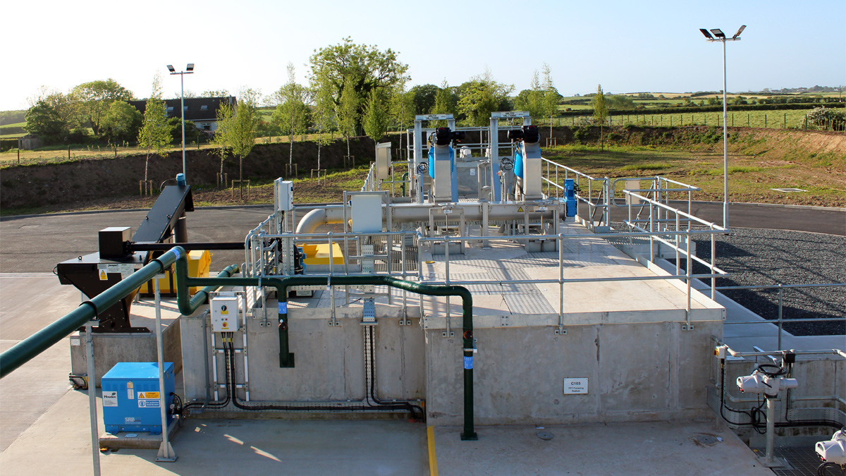
Ards North WwTW – Inlet works overview – Courtesy of BSG Civil Engineering Ltd
Scope of works
The main elements of work included:
- Installation of 14km of pumping main between WwTW & new/upgraded pumping stations via directional drilling and open cut methods.
- 2km of gravity sewer installed between pumping stations.
- 6mm inlet screening and storm storage for 2 hours/3x DWF)
- Grit treatment and removal.
- 3 (No.) 131m3 primary settlement tanks with automatic desludge and scum removal.
- Return activated sludge (RAS)/surplus activated sludge (SAS) pumping station.
- Anti-septicity treatment at source at the pumping stations.
- 3 (No.) 12m diameter final settlement tanks with automatic desludge and scum removal.
- Sludge holding tank.
- Sludge thickening and processing.
- Two-stage odour control plant.
- 330KVA standby power generation.
- 52.28 kwP roof mounted solar PV array, complete with dual 22kWh EV charging points.
- Process flows, levels, and quality monitoring; ancillary processes to support the main process units and intelligent motor control centre (MCC) with telemetry.
- Programmable logic controller (PLC) and human machine interface (HMI) control system.
- Installation of new long sea outfall pipe (detailed in a separate article).
Design criteria for the Ards North WwTW
Due to the large number of caravans in the area expected to be served by the new Ards North WwTW, the plant needed to be designed to deal with significant variations in flow and load to ensure satisfactory treatment could be achieved throughout the year. This meant that the works had to cope with a summer population equivalent (PE) of 8508 and a PE of 4809 in winter months.
Inlet works & flow control/balancing
Flows up to Formula A from the outlying stations can arrive at WwTW simultaneously. The inlet balancing chamber balances out flows going forward to the inlet screening plant.
The inlet screening plant consists of two duty/standby incline screens and a cross conveyor. Each screen has a manual inlet penstock installed to enable isolation for maintenance purposes, or for bypass through the static 6mm bar screen.
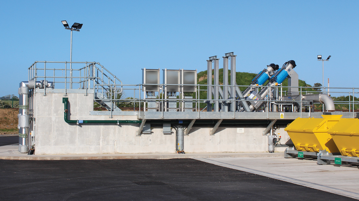
Inlet works side view – Courtesy of BSG Civil Engineering Ltd
Screened raw sewage continues to the grit removal plant. The grit settles in a sump underneath the grit paddle. Any grit that settles in this sump is periodically aerated using the grit blower and then removed. From here the grit is transported out of the grit plant by the grit classifier and is deposited into the grit skip. From here it is removed off site for disposal.
After the wastewater has passed through the grit removal plant, flow continues to the FFT pumping station. Here influent is collected, and FFT of 48.2 l/s (summer) & 29.6 l/s (winter) is pumped to the PST flow splitting chamber.
Ards North Wastewater Improvement Scheme: Supply chain – key participants
- Client: NI Water
- Project management: Tetra Tech
- Principal designer/contractor: BSG Civil Engineering Ltd
- Structural, hydraulic & process design: Doran Consulting
- MEICA design: BSG Civil Engineering Ltd
- Temporary works design: MEA Ltd
- Electrical installations: AW Control Systems
- Dewatering: Causeway Geotech
- Aeration equipment: Xylem Water Solutions
- Aeration blowers: Aerzen Machines
- Sludge thickeners: Huber Technology
- MCC: LMP Controls
- Inlet screening: M and N Electrical and Mechanical Services | Hydro International
- Grit treatment: Jacopa
- Storm screening: Eliquo Hydrok Ltd
- Actuators: Rotork
- Septicity dosing & booster pumps: FM Environmental
- Half bridge scrapers & access flooring/metalwork: Graham Steelworks & Engineering Ltd
- Odour control plant: John Cockerill Environment
- Pipes & fittings: APP Fusion Group
- Standby generators: PM Power
- Poly dosing plant: ProMinent Fluid Controls (UK) Ltd
- Micro-strainers: Whitewater Care
- Photovoltaic solar farm: Solmatix Renewables Ltd
- DO/MLSS & turbidity instrumentations: Hach Lange
- Flow meters & ultrasonics: Siemens
- Tipping buckets: CSO Group Ltd
- Precast concrete supplies: FP McCann
Stormwater storage
When incoming flows exceed FFT, the FFT pumping station will start to fill and eventually overflow to the blind storm tank. Once the blind storm tank has reached maximum capacity, flow will backup, allowing the level within the FFT pumping station to increase further. A higher-level overflow pipe allows flows to pass to the online storm tank. Once maximum capacity is reached here, flows will pass to the Ganaway Burn via the 6mm overflow screen and flow meter.
Storm return will occur when the FFT pumping station is at a suitable low level. The storm tanks will return flow to the FFT pumping station in sequence i.e. blind tank first. Both tanks are fitted with automated penstocks which will open to return the contents of each storm tank to the FFT pumping station. Both storm tanks are fitted with tipping bucket cleaning systems from CSO Group Ltd, which help prevent build-up on the tank floor to achieve that ‘brushed floor effect’ when empty. The tipping bucket will operate when each of the storm tanks has reached the empty level.
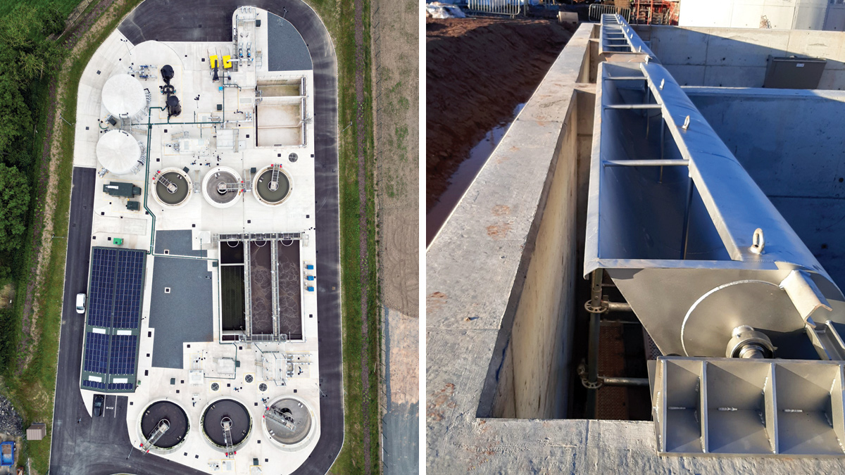
(left) Ards North WwTW – Courtesy of NI Water, and (right) storm tanks tipping bucket installation – Courtesy of BSG Civil Engineering Ltd
Primary treatment
The PST flow splitting chamber receives flows from the FFT pumping station and return liquors pumping station. Flow from the PST flow splitting chamber passes to three primary settlement tanks. These tanks are hopper bottomed and are desludged using automated valves to the primary sludge pumping station. Wastewater continues through to the PST collection manhole which mixes with RAS upstream of the ASP distribution chamber to feed the three ASP lanes.
Sludge and scum drawn from the three PSTs arrives in the primary sludge pumping station. This station consists of two submersible pumps in duty/standby arrangement and is used to transfer sludge and scum removed from the PSTs to the thin sludge tank.
Activated sludge plant
The ASP lanes are identical in design and equipment. Each lane comprises an anoxic zone and an aeration zone. Each anoxic zone is equipped with a mixer. Each aeration zone is equipped with an aeration grid, air control actuator, air flow meter transmitter, two dissolved oxygen probes and an MLSS probe. Each aeration zone is fitted with mixers and aeration grids with fine bubble disc diffusers, which are attached to a central manifold which then connects to the ASP blowers. The influent entering these zones is controlled to maintain a set dissolved oxygen and MLSS level.
The dissolved oxygen demand is supplied via the ASP blowers, configured in a duty/assist/standby arrangement. The blowers’ manifold is monitored by a pressure transmitter, a temperature transmitter and an air flow meter transmitter.
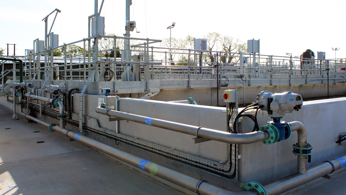
Aeration plant air manifold control valves and instrumentation – Courtesy of BSG Civil Engineering Ltd
Final treatment
Flow from the ASP Lanes gravitates to the FST flow split chamber, fitted with adjustable weirs where the flow is split evenly to the three final settlement tanks. Each tank is identical and is equipped with a half bridge scraper, sludge blanket detector, ladder position switch and a proximity switch. Scum travels to the scum collection chamber and furthermore to the FST scum pumping station. The station is equipped with a duty/standby pump set which pumps its contents to the thin sludge tank.
The tanks desludge is controlled via flow meters through actuated hydrostatic valves located in separate chambers that adjoin the RAS/SAS pumping station. Each tank’s settled effluent hydraulically discharges into the tank’s outlet launder channel to the final effluent/washwater pumping station.
Final effluent
Final effluent flows into the final effluent/washwater pumping station and on to the final effluent sample chamber. Here, the final effluent is monitored for turbidity and temperature levels and is also the dedicated location for the auto sampler.
The final effluent/washwater pumping station contains two submersible fixed speed final effluent/washwater pumps in a duty/standby arrangement. These are used for supplying the washwater tank with the necessary effluent for washing the screens, sludge thickeners, etc. Final effluent is returned through a packaged plant automatic backwash strainer system located inside the control building.
The automatic backwash strainer system, situated inside the sludge thickening building, is a filter that is used to remove particles from the final effluent returned from the final effluent/washwater pumping station.
Final effluent flows from the sample chamber which is connected to the long sea outfall pipe.
Sludge pumping, treatment & storage
The RAS/SAS pumping station is equipped with two sets of pumps. RAS pumps and SAS pumps, a level ultrasonic and high-level floats are used to control both sets of pumps. The duty pump returns the desludge from all FSTs back to the PST collection manhole, continuing to the aeration distribution channel. The SAS pumps, also arranged in a duty/standby configuration, periodically pump forward sludge to the thin sludge tank. The frequency is operative set to maintain a desirable MLSS level within the ASP lanes.
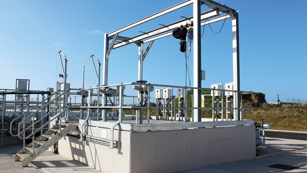
RAS/SAS pumping station – Courtesy of BSG Civil Engineering Ltd
The thin sludge tank is equipped with an external mixer for the blending of the tank’s contents to feed the sludge thickening plant. A level ultrasonic with low and high-level floats are used in the control of the mixer.
Mixed sludge from the thin sludge tank is pumped to the sludge thickening plant via the two thickeners feed pumps. These pumps are progressive cavity pumps and are arranged in duty/standby configuration. The pumps are VSD controlled to allow the flow to the thickening plant to be controlled.
There are two sludge thickeners, with an individual throughput of 8.3 m3/hr @ 1.3% DS with a discharge of no more than 6%, based on a 5-hour day, 7-days per week operation at 100% of the maximum design load. The thickeners are arranged in a duty/standby configuration with two actuated isolation valves installed on the feed pipework allow this to be fully automated. If one thickener was to develop a fault, the standby thickener can resume operations without manual intervention.
Polyelectrolyte is made up on site to be added to the sludge fed to the sludge thickening plant. The addition of this chemical aids flocculation and makes thickening easier.
This plant is a liquid polymer set. The liquid poly is delivered within IBCs for the makeup process. The set mixes the poly from the IBC with water to a preset concentration rate and is then transferred to the poly storage tank. The duty poly dosing pump doses to the thickener’s sludge feed pipework from here.
Thickened sludge from the sludge thickening plant is transferred to the thick sludge tank. Here thickened sludge is stored for removal off site. A collection tanker removes the tank’s contents off site by coupling to the tank’s Bauer Coupler connector.
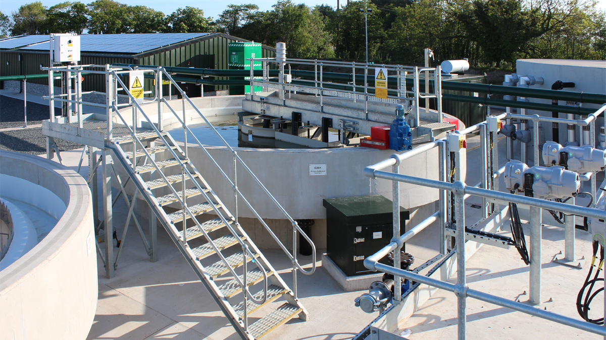
PST No 1 & control building – Courtesy of BSG Civil Engineering Ltd
The tank is equipped with a decant valve arrangement to facilitate settlement of the tank’s contents. The tank is also equipped with a level ultrasonic, low and high-level floats for level status and control of an externally fitted mixer for tank agitation.
The return liquors pumping station receives liquors from the following areas: inlet works drains, thin sludge tank decants and overflow, thick sludge tank decants and overflow, sludge thickening plant bund, FE and washwater drains and odour control plant drains. The station comprises of two fixed speed pumps, which are arranged in duty/standby arrangement. These return liquors to the activated PST splitting chamber.
Washwater pumping
The final effluent washwater & potable water booster sets are positioned within the sludge building. A ’dual washwater tank’ system is in place to feed both sets of pumps. The GRP dual washwater tank is designed with a lower compartment which holds 6m3 and an upper compartment which holds 1m3.
The lower compartment is designed to contain the final effluent delivered via the final effluent/washwater pumping station, which in turn feeds the final effluent booster set which boosts the pressure as required for the washwater of the inlet screens, sludge thickeners, odour control, and the storm tank tipping buckets. The upper compartment is designed to contain potable water which in turn feeds the potable water booster set, which boosts the pressure as required for the nine retractable hose reels around the site for wash down, poly makeup plant water and poly carrier water.
Low level structures RC concrete installation – Courtesy of BSG Civil Engineering Ltd
Odour control plant
The 2-stage odour control unit (bio & carbon filter) is connected to the various strategic areas. The odour control unit comprises of two odour fans, which are arranged in duty/standby arrangement. Actuated valve, flow meters, pressure transmitters and temperature transmitters are used to control the odour control system.
Only odour omitted from the sludge thickening building (due to their extreme odorous compounds) will bypass the biofilter and go directly to carbon filter for treatment.
Outlying pumping stations
Existing treatment facilities at Ballywhiskin and Carrowdore were decommissioned and replaced with new pumping stations, while a completely new pumping facility was constructed at Sandycove Caravan Park where no NI Water asset previously existed.
The last of the outlying WwPS to be upgraded was Ballywalter Fowler Terminal Pumping Station (TPS). This facility was completely refurbished with larger capacity pumps, a new MCC and additional storm storage capacity. Fowler Way TPS pumps to Sandycove WwPS which in turn pumps to the new Ards North WwTW, while the pumping stations at Ballywhiskin and Carrowdore pump directly to Ards North.
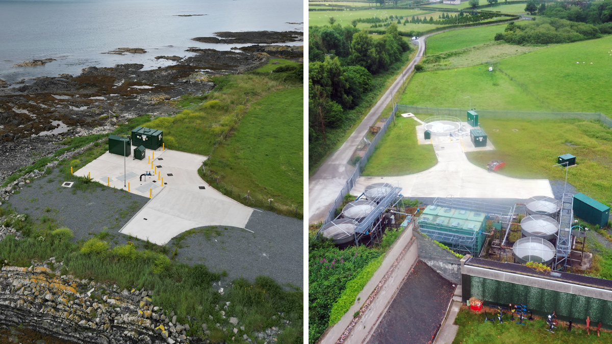
(left) Ballywhiskin TPS – Courtesy of NI Water, and (right) Carrowdore WwPS – Courtesy of BSG Civil Engineering Ltd
Civil construction challenges
There were various challenges throughout the construction phase of the works that had to be overcome to ensure that the contract programme was achieved.
As the project spanned over a 20km distance, there were varying ground conditions to deal with from very loose running sand in the gravity pipeline sections at Sandycove; soft, deep peat at Carrowdore WwPS; extremely hard rock at Ballywhisken to stiff clays with loose gravels at the WwTW site.
This led to a variety of temporary works systems having to be designed and employed to deliver the works safely. Groundwater levels also varied across the scheme with various dewatering techniques used to maintain dry working spaces. Artesian water pressure and groundwater under tidal influence presented difficulties during the construction of these works.
Overhead services also presented a construction issue at the WwTW site. As a result, carefully planned construction sequencing and specialised plant were employed.
13.5km of pumping main was installed along roads within this rural area. In order to keep to programme, pipe installation had to be carried out using a minimum of two separate teams at all times. Due to the limited options for suitable diversionary routes in the area, the pipe installation programme had to be carefully managed and continually communicated to the roads authority to ensure both pipe installation squads had consecutive sequencing of works throughout the pipeline installation phase of the scheme.
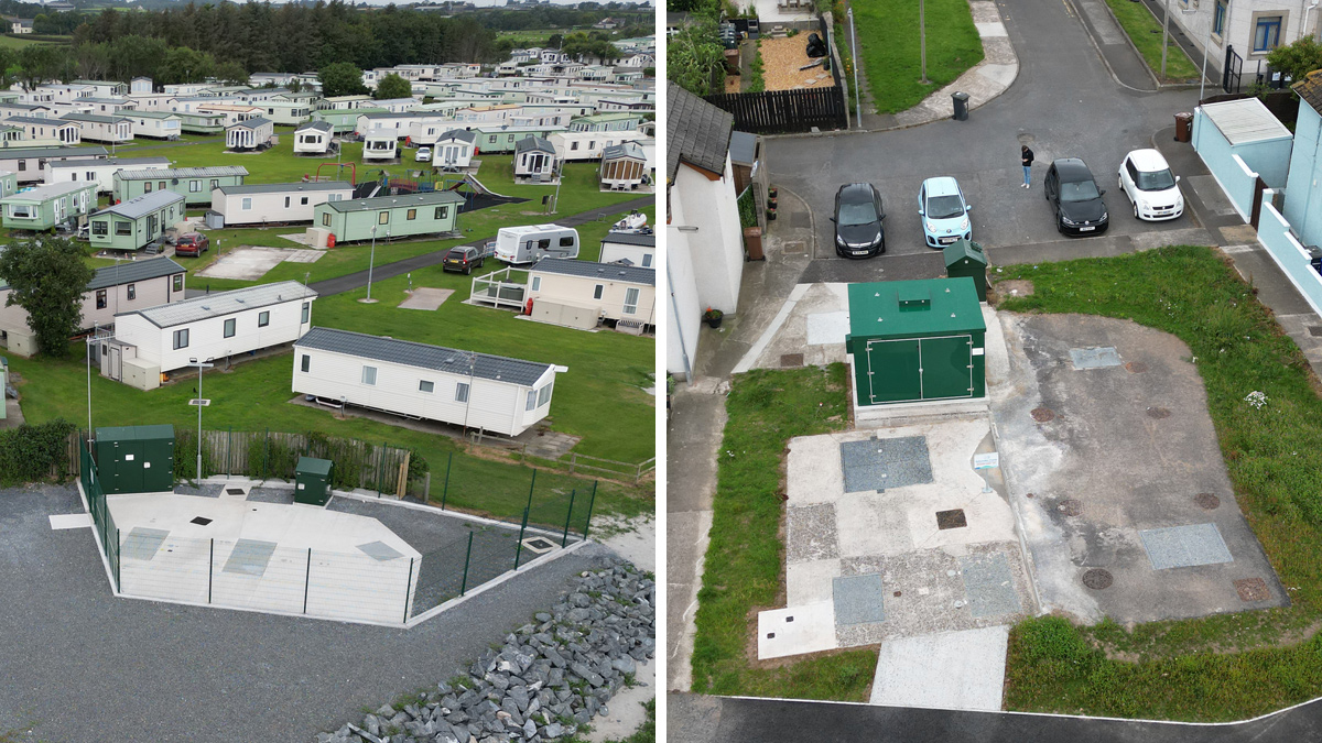
(left) Sandycove WwPS and (right) Ballywalter Fowler Way TPS – Courtesy of NI Water
Sustainability
To boost the sustainability of the treatment facility, 138 solar PV panels from Solmatix Renewables Ltd were fitted to the roof of the new control building which will produce over 45,000 kWh per annum. This renewable energy could save NI Water up to £300k over 25 years. Charging points for NI Water’s growing fleet of electric vehicles have also been installed at the new treatment works.
Communications & PR
NI Water and its project management team developed a proactive comms and PR strategy for the Ards North Wastewater Improvement Scheme which included circulation of project brochure, issuing of regular press releases, letters to residents, briefings for elected representatives, circulation of progress updates, safety events with children, and face-to-face meetings with landowners.
Myriad stakeholders were kept up to date with progress and informed in advance of pipelaying works and associated traffic management arrangements. Following completion of the project, a site tour of the new WwTW was organised to give local elected representatives the opportunity to view the modern facility first hand. Feedback from the visit was extremely positive.
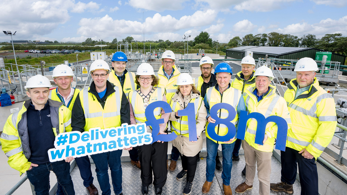
NI Water, TetraTech, BSG Civil Engineering Ltd and Farrans along with local elected representatives to mark completion of the £18m Ards North Wastewater Improvement Scheme – Courtesy of NI Water
Conclusion
A collaborative, forward-thinking approach between NI Water, BSG Civil Engineering and Tetra Tech has produced whole-life cost, programme and carbon savings in the delivery of this project.
Phased flows were brought into the new Ards North WwTW between the months of November 2022 and January 2023. During this time, a process optimisation phase took place before the plant was rigorously tested and commissioned under varying flow and load scenarios. The plant was then put through a period of intensive detailed process sampling achieving highly performing results during separate 14 and 28-day sampling periods during Spring 2023.
The project was successfully completed and handed over to NI Water ahead of the 2023 summer tourist season. The new Ards North WwTW is ensuring that high-quality effluent is being discharged out to sea, helping to improve the bathing water quality along this part of the Ards Peninsula in line with the project objectives.