Chalton WRC (2018)
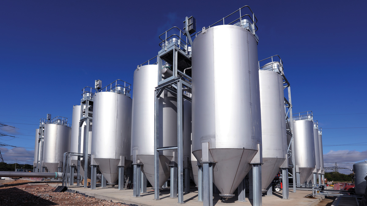
Tertiary treatment plant - Courtesy of @one Alliance
Chalton Water Recycling Centre Water Recycling Centre (WRC) receives influent from the north parts of Luton with an average flow of 240 l/s and a population equivalent of 89,000. The plant has to treat all flows with no storm overflow. The existing works is fed under gravity by three inverted siphons and has seen peak flows of over 600 l/s. The existing works consists of a traditional elevated inlet works and primary settlement tanks followed by a secondary treatment stage of which biological filters and humus tanks work in parallel with a two-stream oxidation ditch and final settlement tanks. The oxidation ditch takes approximately 80 l/s along with the centrate from the sludge treatment area.
Consent standards
As part of the No Deterioration programme of works, Anglian Water was advised that the consent was to change from a 5 mg/l ammonia to a 1 mg/l ammonia on 1 April 2018 and that the plant had to be compliant by that date.
The site also experiences issues with localised overflows under high flow events through the inlet works and primary tanks. As part of the project the team had to address this issue by balancing/holding of the high flows.
The @One Alliance was chosen by AWS to design and deliver this project under the Capital Works Programme.
Process solution – basis of design
The project was split into two distinct areas.
- Balance tank system at the inlet area.
- Tertiary treatment plant at the end of the existing process stream and other modifications to the existing works to enable the consent to be met.
Balance tank system
Chalton receives most of its influent from Luton with only a small local catchment and leachate from a local landfill. Close collaboration with Thames Water who manage the Luton catchment, allowed us to hydraulically model the likely flows and durations for various storm events. The capacities of the existing process units were assessed and a maximum flow of 520 l/s was agreed for the design of the works. As the works is fed by gravity and flows in excess of this had been experienced, the decision was taken to divert one of the siphons directly into the balance tank system rather than go through the inlet works. This would allow the existing inlet works and screens to be used up to their capacity and not have to replace them with new assets.
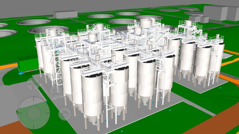
3D model of plant pre-assembly – Courtesy of @one Alliance
Using 1 in 100-year storm event as the basis of design, tanks with a capacity of 2000m3 were chosen. An assessment of alternatives based on this capacity, were reviewed with the following solution providing best valve:
- Flow control penstock up stream of the existing inlet flume.
- Overflow weir after the screen.
- Diversion of the high flow siphon directly to balance tank.
- 500m3 Balance Tank 1. This would receive all flows into the system and return them to the inlet works when flows had reduced. A jet cleaning system was to be installed. A high-level overflow from tank 1 would then feed Balance Tank 2. This same pipe would also be used to return the contents of tank 2, via a small flap valve, so that they could be returned to the works.
- 1500m3 Balance Tank 2. This is a blind tank. Both balance tanks are Permastore tanks, installed by Hayes GFS Ltd tanks, and are the same height as the existing inlet works so cannot overflow even when full.
- Return pumps by Gormann Rupp.
- Jet mixer by Xylem Water Solutions.
- Interconnecting pipework and valves.
- Power and control.
Sludge process
An assessment of the existing plant showed that the sludge treatment process needed to be modified to reduce the risk of plant failure and to allow it to comply with the revised ammonia consent.
The sludge need to be treated efficiently to reduce the possibility of solids carryover through the process and production of septic sludge. The modification consisted of:
- Replacing the existing sludge cake pump with a screw conveyor which would be more reliable and also reduce the power requirements of the sludge plant.
- A new polyelectrolyte dosing system to replace the existing that was prone to blockages.
Tertiary treatment process
For the tertiary treatment process an extensive assessment of the available technologies was carried out with the following solution being confirmed as providing best value alongside process capability:
- Feed pumping station.
- Auto washing strainer with manual bypass unit.30 (No.) continuously washing nitrifying sand filters.
- Process and motive air system, including 4 (No.) 35Kw compressors.
- Flow distribution system using passive weirs.
- Ammonia monitoring system.
- Flow recirculation system.
- Dirty washwater sand trap system.
- Automation, power and control.
- Interconnecting pipework and valves.
- New 11Kv transformer and compound.
- Standby generation with export facility.
- Power distribution.
Integration
During the design and integration phase of the project core @one Alliance principles were applied, including:
- Benefits by design: Utilising standard products, proven designs, 3D and digital systems and innovative design to enable efficient integration, reduce carbon and cost and reduce assembly time on site.
- Industrialised construction: Maximising the use of off-site build with all of the supply chain partners, bringing benefits in Health and Safety, efficiency and reduced time on site.
Modelling
3D modelling was used for the design of the two areas from the start of the project. Each contractor created and updated their models for their own elements of the project.
These were combined into a single integrated model which was then used for design reviews, clash detection at interface points and project rehearsals. Using standard products and details proved beneficial and saved time in creating the integrated model and the design in general.
The works at Chalton had been developed and modified at regular intervals since it was built in the 1960s. Although surveys did exist for some areas, a programme of topographical surveys, intrusive trial holes, service investigations and 3D laser surveys was undertaken to provide accurate up to date information on which to base designs.
Balance tank area
The balance tank system needed to be built in close proximity to the existing inlet works. A location was identified and the decision taken to provide two balance tanks rather than one. Due to the predicted nature of the use of these tanks and the space available, a 500m3 tank was used for the initial flows with a secondary 1500m3 tank being used for prolonged storm flows.
The interconnecting pipework between the two tanks was designed such that it could act as a flow and return pipe. A flap valve on this pipe stops premature flows going to tank two whilst still allowing a return flow without the need for expensive actuated valves.
Design decisions were taken with the core @one Alliance principles in mind, specifically:
- Pipework and cabling was to be above ground wherever possible to avoid clashes with existing services or service strikes. The connecting pipe between the two balance tanks was run above ground and the site access road was realigned to remove the need for a buried road crossing.
- The balance tanks were designed to be built above-ground, so glass coated steel tanks were chosen which significantly reduced the installation time compared to concrete tanks and reduced the amount of embodied carbon.
- A standard product was used for the MCC kiosk and the panel was constructed by one of the framework partners, Paktronic Engineering Company Ltd.
Tertiary treatment plant
The tertiary treatment plant (TTP) needed to be built at the end of the existing process, prior to a set of final settling lagoons. A large area existed beyond the existing humus tanks; however a good proportion of the land could not be used due to high voltage cables crossing the site. A programme of surveys and trial holes was undertaken to confirm that this location was suitable.
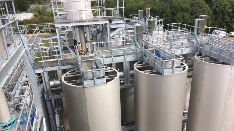
Upper level of the TTP – Courtesy of @one Alliance
The final location chosen was originally the site of four old biological filters that had been demolished some years before. Although the above ground elements had been removed, the base slabs were still in place approximately 1000mm below existing ground level. These bases were tested for structural capacity and integrity and were then incorporated into the new filter support slab, thus saving the need to remove and dispose of them as well as reducing the amount of new concrete required for the new slab.
A disused humus tank was used as the basis for the feed pumping station. A number of modifications were made to this tank to convert it into a pumping station, including modifying the existing humus tank outlet channel to create the new inlet to the pumping station, new duty, assist standby pumps and pipework to the new sand filters. The new outlet chamber for the tertiary treatment plant was designed so that it could be constructed around the existing 1125mm concrete outfall main while the pipe remained live.
A penstock would isolate the two sections of the chamber after the pipe within the chamber had been removed. This chamber was split so that one section takes the outlet flows from the new plant to the outfall, the other section takes the recirculation flow back into the existing channel system. This design negated the need for new separate buried pipes for pumping station overflow and recirculation as the existing outlet main was reused. This saved both money and time on site.
The design for the tertiary treatment plant was carried out by Colloide Engineering systems using their standard continuously washing nitrifying sand filters. The unusual element to this design was the number of filters used. A total of 30 (No.) filters, in six streams of five was proposed with a cascade flow distribution system. As with the other design on site decisions were taken with the core principles in mind, specifically:
- Pipework and cabling was to be above ground wherever possible.
- All 30 (No.) filters were exactly the same, pipework support gantries and access ways were all designed to be brought to site, as pre-assembled units in order to reduce site assembly time and reduce design time.
- Standard product MCC kiosks were used. Due to the amount of power cables from the generator and transformer and a necessary road crossing a standard product cable trench was used.
- The new generator was a standard product, supplied in a container for speed of assembly on site.
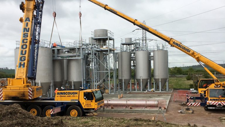
TTP during assembly – Courtesy of @one Alliance
Integrated team
The fully integrated team included staff from operations, contractors, construction and commissioning and all provided input and review of the proposed designs, so that the whole team was happy that the solution could be safely assembled, commissioned, operated and maintained.
The integrated 3D model was used to engage with all project stakeholders through regular reviews. It was also used to carry out an initial ‘safe to operate’ review, project rehearsal and peer reviews, all prior to starting on site. This was to identify any issues in the design so that they could be rectified before commencing work on site, so therefore reducing time on site and minimising costly rework.
Chalton WRC – Table of designers, contractors and main suppliers
- Designer: @one Alliance
- Principal contractor: @one Alliance – Stantec
- Tertiary Plant Partner: Colloide Engineering Services
- Tier 2: Civil partner: Coffey Construction Ltd
- Tier 2: Mechanical (Inlet area): Saviour Engineering Ltd
- Tier 2: Electrical (inlet area): Field System Design Ltd
- Tier 2: MCC partner: Paktronic Engineering Company Ltd
- Glass coated steel tanks: Hayes GFS Ltd
- Generator: Stuart Power Ltd
- Transformer and HV: Freedom Ltd
- Pumping station bridge: Steelway Ltd
- Polyelectrolyte dosing: NPS Ltd
- Sludge conveyor system: Euroby Ltd
Assembly
Pre-planning: Prior to commencing on site, the team carried out a number of project rehearsals. At these rehearsals the assembly sequence is challenged and modified so that when work does start on site, the construction team is not building the project for the first time. This process works to engage all of the supply chain partners, construction teams and commissioning teams as well as the design team to develop a buildable solution in a truly collaborative manner.
For the project at Chalton a number of rehearsals were carried out due to the size and complexity of the project. The first concentrated on the balance tank system and works in the inlet and sludge handling areas. The second and third working through the civil engineering and tertiary filter works for the tertiary treatment plant.
With the number of filters, access ways, pipe gantries involved, traffic movements and crane operations were key activities on site and the project rehearsal process allowed us to ensure that these were explored and challenged, so that there were no surprises when we were on site. The resulting traffic management plan included crane locations and numbered vehicles so that all knew where the vessels and fabrications had to go when the assembly process commenced.
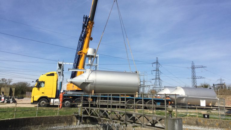
Off-loading pre-assembled filters – Courtesy of @one Alliance
Site work: Work started on site in January 2017 with the new concrete bases for the filters being the first items to be built. At the same time the first filters were being fabricated in Ireland along with the pipework gantries, access walkways, distribution tanks and pipework. A trial assembly was carried out for the first streams at the fabrication yard and any minor changes were carried out there prior to the structures being dismantled and then shipped to Bedfordshire. This approach ensured that when the units arrived at site they fitted together exactly as they should.
BIM360 glue was used to share the integrated model amongst all parties and was used extensively by all of the team throughout the assembly on site. This helped to minimise the number of technical queries as construction drawings could be seen in context.
Media was placed in the filters and flushing commenced in September 2017, nine months from starting on site, with the filters being on line following seeding, in late November 2017.
Conclusion
Due to the processes and techniques used on the scheme such as standard designs, project rehearsals, constructive collaboration the project has saved over 45% on embodied carbon and over 4 months on the typical assembly period for a project of this type once on site.
The balancing tank and flow control systems were commissioned in February 2018, along with the sludge conveyors and polyelectrolyte dosing equipment. The tertiary treatment plant was treating the effluent to the required ammonia standard by the obligation date of 1 April 2018. The benefits of collaboration, off site build and innovative design can clearly be seen in the project at Chalton.


