Drumaroad Clear Water Basin (2022)
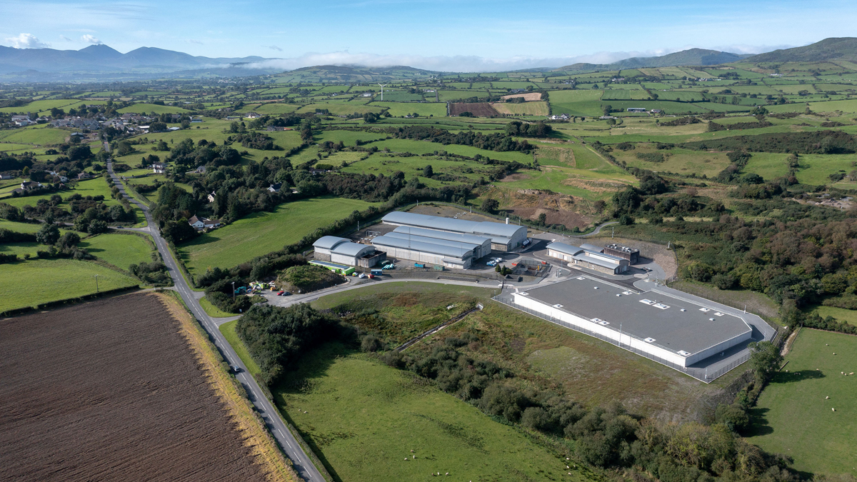
Drumaroad CWB - Courtesy of NI Water
Drumaroad Water Treatment Works (WTW) supplies water to many households throughout Northern Ireland. A 2013 report commissioned by NI Water identified the need for increased potable water storage facilities within the Drumaroad Supply Zone to reduce the risk of water shortages under certain network situations. As part of a £13m investment to modernise the existing water infrastructure to ensure security of supply and resilience to the water distribution network, a new 35.7 ML clear water basin (CWB) has been constructed on land adjacent to Drumaroad WTW. The project was successfully commissioned and handed over to NI Water in November 2021.
Project background
Drumaroad WTW typically produces on average 100 ML of potable water per day for the supply of the distribution network, with a design capacity to provide up to 140 ML per day. Water treated at the works exits the site via two pumped mains, which are individually flow controlled and metered. There was no existing storage at Drumaroad WTW, meaning all water that was treated had to be immediately pumped off site, offering no resilience or flexibility for NI Water.
The need for investment
The findings of a report carried out in 2013 on behalf of NI Water, ranked the potable water storage facilities at Drumaroad as one of the highest risks across all Northern Ireland Service Reservoirs (SR) and CWBs in terms of low storage retention times. The report identified the need for a suitably sized reservoir within the Drumaroad Supply Zone. Should a suitable storage facility not be provided there was a high risk that NI Water customers could suffer water shortages under certain network situations.
Business case development
RPS were commissioned by NI Water to develop a business case and provide a recommendation to address the low storage retention times within the Drumaroad Supply Zone.
Following an optioneering exercise, the approved business case concluded with the recommendation to construct a new 35.7 ML clear water basin on land adjacent to the existing WTW which NI Water already owned. The new CWB would increase the existing storage capacity and provide security of supply to the potable water distribution network, meeting business case objectives and offering a cost-effective solution.
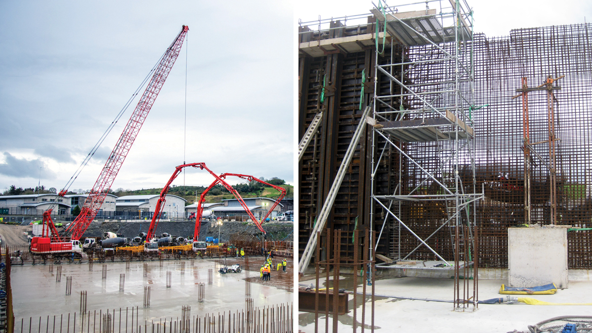
(left) The base pour and (right) the wall pour – Courtesy of GRAHAM
Project delivery
Following successful approval of the Business Case, RPS was retained as Technical Advisor and NEC Project Manager for the delivery of the project. GRAHAM were initially engaged under an Early Contractor Involvement (ECI) Contract to successfully develop design and challenge existing standards. They were involved in introducing innovative construction methods, while overcoming unique challenges in conjunction with the entire contract team, which was fundamental in the successful delivery of the main project. GRAHAM were subsequently awarded an NEC ECC Option C contract for the construction of the new CWB.
Location of new clear water basin
The site of the new CWB is located on land adjacent to the existing Drumaroad WTW in Co. Down. The land was within the existing NI Water ownership boundary, resulting in reduced project costs and eliminating potential issues associated with land acquisition.
Project scope
GRAHAM were initially commissioned under an ECI contract to develop the design, challenge existing standards and introduce innovative construction methods. Following design sign-off, a target cost was agreed and an NEC ECC Option C contract awarded for the detailed design, construction, commissioning and testing of a new 2-compartment, 35.7 ML storage capacity CWB and all associated works.
The scope of work required design and assessment from civil, mechanical, structural and geotechnical engineers. There was also a requirement to carry out computational fluid dynamics modelling along with detailed design drawings which progressed in accordance with BIM procedure.
As per the requirements of the Reservoirs Act (Northern Ireland) 2015, a construction engineer from a list of appointed Panel of Engineers was appointed by GRAHAM and their designers AECOM, to oversee the design and construction of the new CWB.
The project for the new Drumaroad CWB consisted of the following:
- Extensive site investigation, water course and utility diversions and earthworks.
- A new 35.7 ML twin compartment reinforced concrete CWB and all associated works including pipework and valves.
- Valve gallery and pumping station to house all necessary pumps, pipework and valves integral to the compartment(s) structure with appropriate access, lighting and ventilation.
- MCC control room.
- New 1400mm inlet and 1200mm outlet mains and 600mm connection main for Newcastle.
- Pipework connections to existing pipelines ranging between 1600mm and 900mm diameter pipework.
- Provision of chlorine residual monitoring and dechlorinating facilities.
- Landscaping, access road and security fencing.
- New scour and drainage pipework to service the CWB and site.
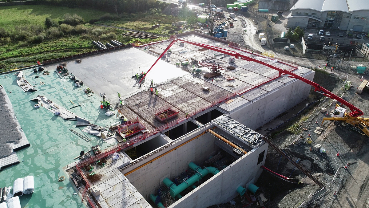
Valve chamber with the roof off and gantry – Courtesy of GRAHAM
Ground conditions
Results from extensive ground investigations which were carried out prior to the commencement of the design allowed the construction and design team to assess and agree on the most suitable location for the CWT. The ground investigations identified deep peat on the eastern side of the site and strong rock on the western side. The tank was shaped and positioned on the site to avoid extensive peat excavation.
CWB structure
The CWB comprises two compartments of approximate equal size, and an integrally constructed valve pipework and pumping station gallery. The structure is partly buried into the existing ground, with embankments built-up where practicable surrounding the tank, except for the valve gallery where a paved road and footpath gives level access to the valve gallery, pumping station and MCC room. The entire roof of the structure is finished with a handrail.
The overall dimensions of the structure are 98.0m long by 62.45m wide at its widest point. The structure is approximately 8m deep throughout the compartments, accounting for make-up of the roof structure and freeboard above the top water level. Normal water depth is approximately 7.2m.
Each compartment has a baffle curtain arrangement to direct the water flow path within the compartment to remove short circuiting of the water and dead spots creating plug flow. The depth of the valve gallery and pumping station is approximately 11.3m deep to accommodate pipework.
The new CWB has access points in the roof to the compartments, and doors are provided to the MCC room, valve gallery and pumping station. Each compartment has a dedicated access cover to provide access for plant/equipment during maintenance. The pump station contains a loading bay and roller shutter door to provide access/egress for equipment from the pump station/valve gallery area.
All roof access covers have LPCB 1175 Security Level 4 rating whilst all other doors and access have security level 3 rating. All access points are covered by security alarms.
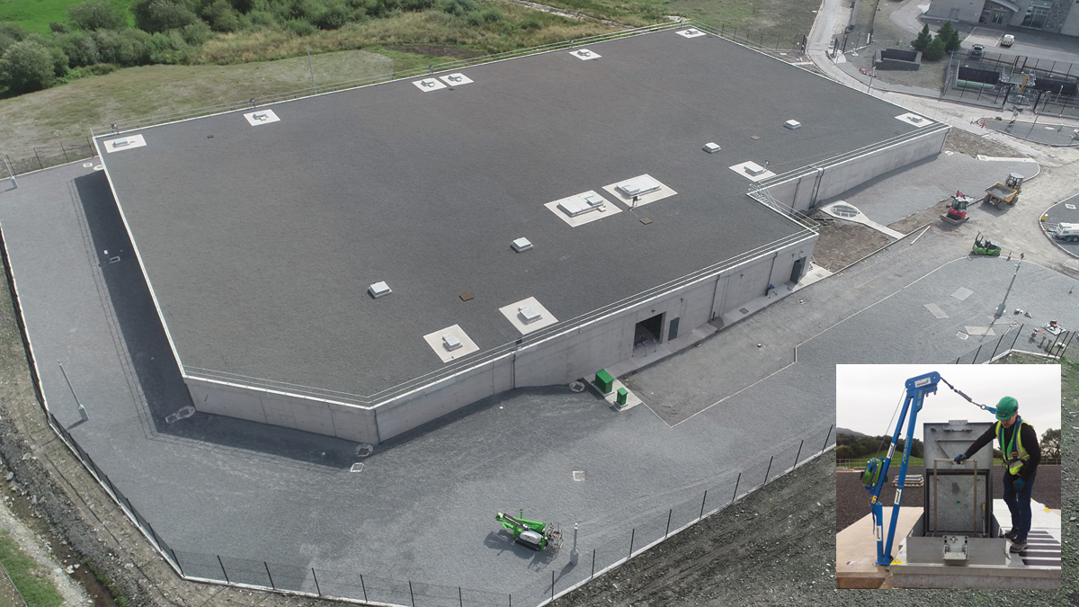
(left) Drumaroad CWB – Courtesy of GRAHAM and (inset) access demonstration – Courtesy of RPS
Permanent access to the new CWB and pumping station is via the existing NI Water access road. The existing road was extended to accommodate HGV vehicle and maintenance vehicle access to the pumping station. The existing security fence and access gate position was modified to accommodate the position of the new CWB within the NI Water Site. Steps have been constructed adjacent to the new access road to provide access to the roof of the new CWB.
GRAHAM commissioned TES Ltd for the design and provision of mechanical, electrical, instrumentation, control and automation (MEICA) elements. The MEICA elements are further detailed in the following schedule of items.
- New transfer pumping station.
- MCC panel c/w future design for solar panel installation.
- Real-time flow and level monitoring.
- Individual compartment chlorine analysis.
- Hatch alarm and security system to LPCB4.
- Fire & intruder alarm system.
- CCTV perimeter security system.
- Level 4 structural lightning protection.
- Street and building lighting.
- Overhead gantry crane for the future maintenance of all pipework, valves and fittings.
- Provision of pumped drainage in the valve chamber.
- V-notch weir flow measurement for scour line flows to drain.
- Fresh air ventilation ducted to the valve chamber and MCC room.
- Full stairway & platform access to all valves and fittings.
- Upgrade of the WTW’s PLC and SCADA software for the additional signals and revised compartment configuration.
Process overview
Extensive hydraulic analysis identified the opportunity to reduce interstage pump running costs by the provision of a band of water that could flow via gravity from the WTW under normal operating conditions. The new CWB hydraulics were calculated to integrate into the hydraulic profile of the existing site with minimal affects to the existing treatment plant and off-site pumping processes. The CWB layout, pipework and cell configurations minimised hydraulic losses through careful selection and sizing of all pipework, fittings, entries and exits.
This hydraulic analysis coupled with the aforementioned ground conditions determined the optimum location and level of the CWB by achieving both the functional performance criteria and a safe, efficient, cost effective construction methodology.
The PLC control system facilitates gravity flow and the pumping of flow from the two CWB compartments to the Dunmore wet well, by automatic control of inlet valves, gravity outlet valves, transfer pumps, and associated instrumentation.
Flow enters the CWB from the WTW by gravity, via a common pipeline which splits to provide a separate inlet pipe to each compartment. Each compartment has an actuated inlet control valve. From each CWB compartment is both an outlet pipe allowing flows to hydraulically transfer by gravity out of the CWB when the level in the CWB compartments is sufficient, and transfer pumps which operate and pump forward flow when the level in CWB falls below the level which would allow transfer by gravity.
The gravity and pumped outlet pipes merge into a common outlet main inside the valve chamber, and actuated valves on the gravity outlet pipes from each compartment open and close as required to facilitate this functionality. There are multiple modes for pump operation to provide flexibility to NI Water Operations for maintenance purposes and in response to network situations. Instrumentation to monitor water quality on the outlet main is provided.
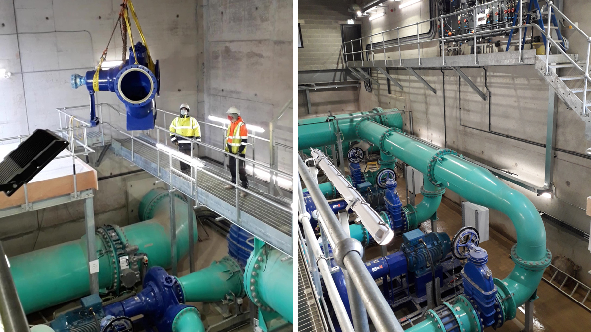
Pumping station – Courtesy of RPS
Proposals to minimise impact to NI Water customers
Minimising impact to NI Water customers was very prevalent in early team discussions regarding the construction of the CWB at Drumaroad. All elements and activities which had a potential impact on customers was considered in detail to ensure, impact could be removed or minimised where possible.
The final position of the CWT was agreed by all stakeholders which allowed the team to confirm the existing services which needed to be diverted to allow construction room for the new CWB. The existing NIE 11kv service which was laid through the NI Water site had to be relocated to facilitate the excavation. NIE agreed with the relocation of the 11KV cable. Local residents were kept informed at all stages of the preparation works so that advanced notice could be provided.
Early consultation with the residents gave NI Water an opportunity to advise residents of the expected work hours for the project. Specific notification was also provided for larger concrete pours as early morning starts and late evening finishing were expected.
These activities were identified during early programme discussions with the contract team. All critical work activities were monitored to ensure disruption was minimised to residents and managed appropriately.
Several large diameter pipeline connections required extensive planning to facilitate lengthy shut-downs of the Drumaroad WTW. Planned works notifications considered construction methodologies, risk assessments and contingency planning. Complex network rezoning ensured that construction works could proceed without interruption to the water supply. During the testing and commissioning process, water was transferred directly from Compartment 1 to Compartment 2, thus avoiding unnecessary water usage and subsequent wastage.
As part of the acceptance and commissioning process, samples were retrieved at low levels within the CWB to ensure the results were satisfactory, prior to progressing to fill the tank to the next level.
Drumaroad CWB: Supply chain – key participants
- NEC4 project manager: RPS
- Principal designer & contractor: GRAHAM
- Civil/structural design & CFD modelling: AECOM
- MEICA, PLCs, SCADA: TES Ltd
- Metalwork, stairways & handrails: Evans Plant & Fabrication
- Precast manholes, covers & pipes: FP McCann
- Precast slabs: Creagh Concrete Products
- Gantry cranes: Walter Watson
- Waterproof membrane: StructureCare
- Shoring: Causeway Equipment Ltd
- Sampler feed pumps: Grundfos Ltd
- Transfer pump manufacturer: KSB Ltd
- Scour pumps: Xylem Water Solutions
- External pipe supply & valves: APP Fusion Group
- Transfer pumps: Drilling & Pumping Supplies
- Analytical Instrumentation: Cully Automation Ltd
- Concrete formwork subcontractor: Ideal Form Ltd
- Butterfly valves: Belgicast International
- Dewatering: Aska Sykes Ltd
- Security fencing: Kane Contracts
- Flow meters & instrumentation: Park Electrical Services Ltd
- Analytical instrumentation: Process Instruments Ltd
- Access steelwork: Graham Steelworks & Engineering
- Security doors: Fortress SEFA
- Concrete pumping: MR Concrete Pumping
- Earthworks contractor: TJ Loughlin Contracts Ltd
Construction technologies utilised to enhance quality, improve site efficiencies amd reduce costs
Modular build hybrid (precast roof): GRAHAM proposed to construct the CWB using an in situ reinforced concrete base and walls, with a precast modular roof overlaid with an in situ concrete screed. The construction of the precast roof allowed works to progress with the in situ walls, while the precast slabs were constructed adjacent to the main tank works.
As the walls, columns and beams were constructed and cured to the required strength, roof slabs were set into position, in preparation for the final screed to be laid to the roof. The primary factor for this methodology was to eliminate and reduce as far as possible the number of man hour’s operatives were working at height on the roof of the reservoir. Secondary factors for this methodology included a reduction in the contract program duration and a reduction in the amount of temporary works required to construct the roof slab using modular construction techniques.
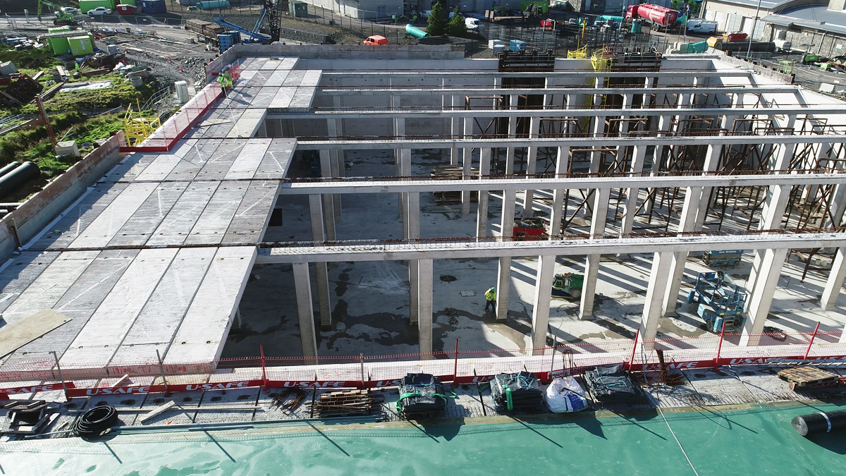
Precast roof slabs – Courtesy of GRAHAM
To eliminate the potential passage of contaminants into the water retaining structure, in accordance with the employer`s requirements, a waterproof membrane was spray applied to the external surface of the roof. The product selected by GRAHAM for the CWB at Drumaroad was a sprayed applied Pitchmastic product. This product is an innovative, polyurethane waterproofing layer, which is spray applied seamlessly, that cures rapidly to form a tough waterproof membrane, which is durable, strong, flexible and with a long-projected service life for NI Water. A protection layer of geofabric and plastic was placed on the waterproofing followed by 150mm layer of single size stone.
Re-use of rock: The excavated rock was tested and crushed on site. This site-won material was used for a drainage layer under the base slab and a drainage layer against the walls. The crushed stone was also used for permanent road construction and temporary works within the site. This extensively reduced the amount of quarry material imported to the site.
All spoil/rock excavated from the site was stored either on site or in the adjacent privately owned land to the north of the site.
Construction methodologies: Early discussions during the ECI process with the supply chain and designers confirmed that the main base would be poured in three separate pours. The size of the structure required careful consideration of cranage radius, concrete pumping lengths, program and access. Base slab pours were made up of a 2,500m³ pour, 700m³ pour and a 1,100m³ pour.
Three concrete pumps (56m, 47m and 42m reach) were used to place the concrete in the base slab with a continuous supply of up to 36 concrete lorries. Concrete was delivered to the required location by the concrete pump tremie pipe and levelled using a screed unit equipped with the latest survey technology to achieve the required gradient of 1:100 at any location on the base.
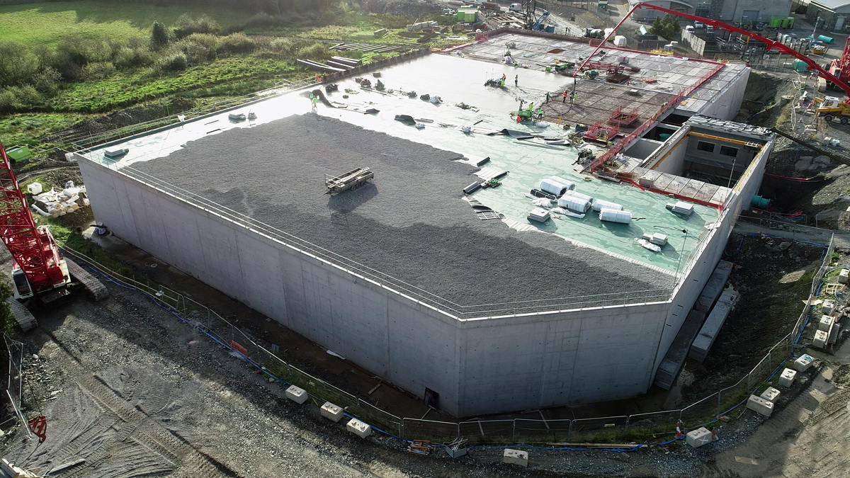
Waterproofing and protection – Courtesy of GRAHAM
Wall pours: The walls were 850mm wide and constructed using a specified design mix, with a 60% GGBS content. Pours were specifically designed to minimise the long-term maintenance for the client by reducing the number of construction joints within the pour sequence. During ECI discussions with the formwork sub-contractor, parameters were agreed in conjunction with the structural designer to maximise attributes such as pour sequencing, shutter rotations, strike time etc. To reduce the time spent working at height, reinforcement for the walls was prefabricated at ground level and lifted into position using approved temporary works arrangements.
The valve gallery and pumping station was identified for early completion to facilitate installation of the pipework, valves, pumps and associated MEICA instrumentation. To ensure this could be completed practically, the permanent overhead gantry crane was installed early in the programme, allowing MEICA works in the valve gallery to progress, simultaneously with the construction of the CWB compartments. The permanent roof of the gallery was left off until all major pipe and pumps were installed.
Stakeholder engagement
The commissioning process was critical to the success of the project. Rigorous civils and MEICA testing involved the project team along with representatives from NI Water’s operational and maintenance teams. Testing was successfully completed prior to the final integration of the new asset and diversion of water, via the clear water basin, to the distribution network for consumption.
GRAHAM engaged a local landowner to secure the use of adjacent lands for storage of materials. Early engagement ensured that operation of the adjacent agricultural land could be maintained as practically as possible, during the site investigation period and during construction.
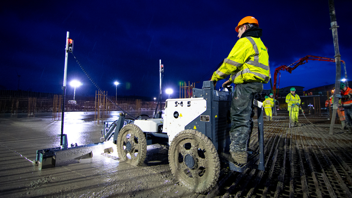
Auto screed – Courtesy of GRAHAM
Summary
The new 35.7 ML clear water basin was successfully commissioned and handed over to NI Water in November 2021, providing security of supply and resilience to the water distribution network to its customers for years to come.


