Elmvale Row Sewer Flooding Prevention Scheme (2016)
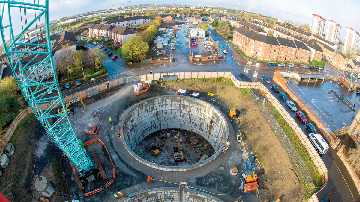
Overhead view of shaft construction and local community - Courtesy of SNS
Elmvale Row is located in the Springburn area in the North of Glasgow City and is comprised of three and four storey residential tenement buildings and residential parking. Land use in the surrounding area includes commercial, residential, parkland and a primary school. The topography of the area and capacity of the existing sewer system has resulted in flooding affecting 24 properties. Scottish Water is committed to removal of properties from the DG5 register so the project was undertaken to remove 10 properties subject to internal flooding from the register and also prevent external flooding of a further 14 properties.
Background
Scottish Water investigated various options to protect against future sewer flooding from a 1 in 30 year storm and engaged Atkins to develop a conceptual solution which consisted of 2 (No.) 25m diameter shafts approximately 24m deep, providing a total of 13,000m3 of storage with flow diversion/screening chambers and associated pipework. The project was to be sited on park land owned by Glasgow City Council at the upper end of Elmvale Row adjacent to the Elmvale primary school.

Elmvale Road flooding – Courtesy of SNS
The site investigation works were carried out by Raeburn Drilling and Geotechnical Limited to investigate ground conditions including composition of superficial deposits and contaminates; rock types, head profile and strengths; groundwater, soil and rock permeabilities; and historical mining activity.
The project was allocated to aBV, a joint venture between Amey and Black & Veatch (now Binnies) – an integrated joint venture responsible for delivery of Scottish Water’s SR15 wastewater infrastructure programme – to complete the design and construction as part of the early start programme under the SR15 Alliance Framework.
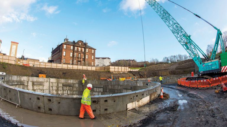
Construction in close proximity to Elmvale Primary School – Courtesy of SNS
Design
As an integrated design and build team amey-Black & Veatch reviewed the conceptual solution prior to commencement of detailed design and target pricing. The review focused on value engineering all elements of the project whilst taking into account proximity to the primary school and disruption to the community. Key elements included shaft design and construction techniques, sequencing of large diameter pipework, maintenance of traffic and management of existing services.
Following the aBV review, the overall twin shaft concept and storage volume remained unchanged. However, design improvements in the arrangement on site, vertical geometry and operation of the shaft (tanks) were achieved through the value engineering process.
The key driver for altering arrangement of the shafts on the site was to avoid the cost and delays associated with relocation of a 900mm medium pressure gas pipeline. Although this change resulted in a slight increase in excavation volumes the net capital savings were £2m against the gas company quotation for relocating the pipeline.
Key drivers for changes in the vertical geometry and tank operation were cost reduction and reducing community disruption. The conceptual solution featured steep 1:2 (horizontal:vertical) concrete benching to create cone shaped hopper bottom tanks which enabled gravity clearing of solids and debris to the discharge pumping sump following a storm event.
The design of the hopper cones required 4m of excavation in rock, much of which would then be backfilled with concrete benching.
VacFlush system
The aBV revised design introduced essentially flat bottom tanks (minim slope) incorporating VacFlushTM systems from CSO Technik (now CSO Group Ltd) to clear the tanks after each storm event. This approach reduced the time and cost of rock excavation, concrete benching and community disruption of additional truck movements.
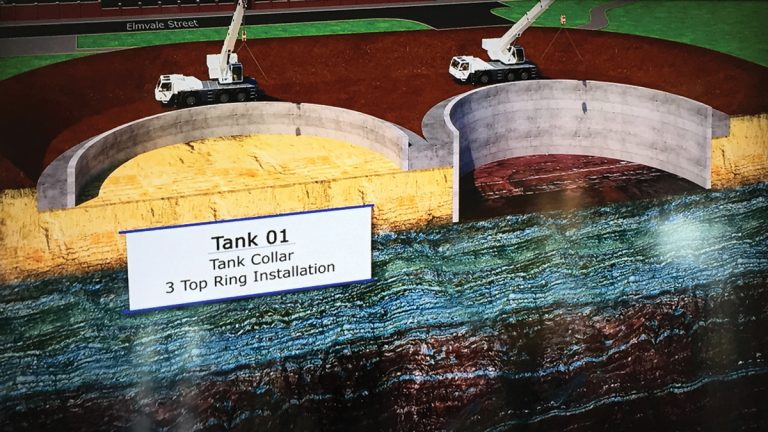
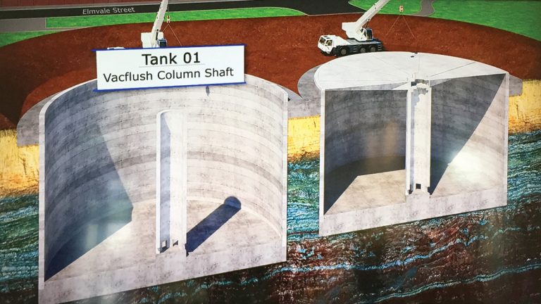
Tank and VacFlush construction sequence 1/4 – Courtesy of Solius
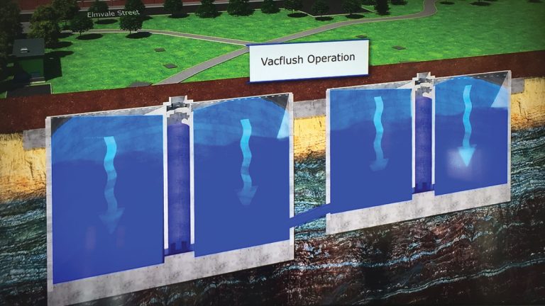
The VacFlushTM system consists of a centre column in each tank with vacuum pumps. During a storm event, flood waters rise in the first tank including its centre column. Once the first tank is filled a high-level overflow spills into the second tank filling it including its centre column. During the storm event the vacuum created maintains the water level in the centre columns. The tanks are pumped down at a controlled rate over 12 hours by the submersible pumps once the sewer network has sufficient capacity.
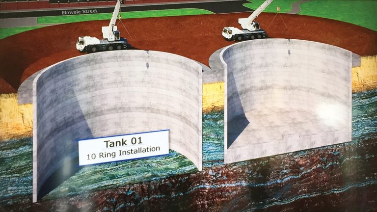
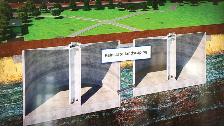
Tank and VacFlush construction sequence 2/4 – Courtesy of Solius
Once the tanks are pumped down, the vacuum on the centre column(s) is released allowing the flushing volume to jet through orifices in the column base across the tank floor flushing solids and debris into a peripheral channel that drains into a small pump sump.
Tank and VacFlush construction sequence 3/4 – Courtesy of Solius
Although the VacFlushTM design requires construction of the centre columns, installation of vacuum pumps and associated electrics/controls, the centre column supports the tank roof which simplifies both the design and the construction. The vacuum pumps and associated works are small in scale and capital cost and the infrequent operation results in minimal operating cost
Tank and VacFlush construction sequence 4/4 – Courtesy of Solius
The net capital savings associated with VacFlushTM design versus the deeper shafts with benched concrete cone bottoms was £1.5m.
A secondary benefit of the VacFlushTM design is that a more sustainable carbon friendly solution was achieved through the 4,000m3 reduction in rock excavation, elimination of 3,000m3 of benching concrete (including associated impacts of aggregate mining and cement processing) and all the associated plant and transport impacts.
Tank and VacFlush construction sequence 4/4 – Courtesy of Solius
Precast
Other innovations include the widespread use of bespoke precast chambers, such as the valve chamber, the flow split chamber and the CSO screen chamber, to allow more off site fabrication. The central vacuum column is made from precast units as are the roof beams and the roof slab is of composite precast construction.
Construction
Construction of the project commenced in March 2015 and has been effectively broken down into two major elements of work:
- The main element of the project being the construction of two 25m diameter storage tanks constructed as shafts.
- The secondary element of the project involved the phased construction of all the associated pipework, manholes and chambers needed to upgrade and connect the surrounding the sewer when required.
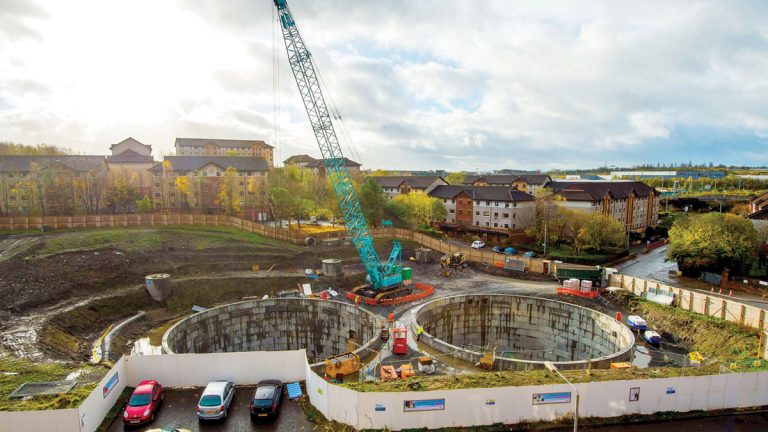
Overhead view of site – Courtesy of SNS
In order to construct the shafts in the parkland, a major earthworks operation was required to level the site, cutting down the centre of the site by approximately 5m to achieve suitable formation level for construction of the reinforced concrete collars at the top of each shaft. This involved removal of 12,000 tonnes of superficial made ground much of which was contaminated with hydrocarbons. This material was not sent directly to landfill but rather to a treatment facility allowing it to be processed and reclassified from hazardous to non-hazardous.
The ground conditions dictated the construction method of the tanks; the presence of rock meant the tanks had to be underpinned as opposed to jacked down. In addition, the presence of the 900mm medium pressure gas main in very close proximity to the works also influenced construction methodology, in that blasting the rock out was ruled out in favour of excavators with peckers.
The twin tank construction was originally planned in a linear order, constructing one shaft to its full depth prior to starting construction of the second shaft. The logic behind this initial programme was that whilst the second tank was being constructed the base slab and internal fit out of the first tank could be completed. However, upon completion of the collar for the first tank, the plan was revised and the second collar was constructed at this stage. This decision was taken largely due to a break in the weather and the effect this had on ground conditions at the location of shaft construction.
Upon completing the collars, the plan was for specialist contractor ASG Tunnelling to commence sequential construction of one shaft followed by the other. However, further optimisation of crane usage, plant and mining resources resulted in a decision to progress both shafts in parallel, excavating in one shaft whilst installing and grouting precast liner rings in the other tank.
Once a ring is completed the operation is alternated, progressing to the next level. This approach resulted in programme savings as the time taken to complete both tanks was effectively the same as the time originally planned to complete one.
The base slab for each shaft required over 100 tonnes of reinforcing steel. In order to reduce time on site, minimise crane operations and worker exposure to handing and tying reinforcement at the base of the 20m deep shafts this reinforcement was prefabricated offsite as large cage sections. Installation on site was rapid with minimal labour effort required to join cage sections prior to concrete placement.
The second component of works involved a major upgrade to the sewer network in the streets surrounding and including Elmvale Row. This involved deep installation of new large diameter sewers and upsizing of existing sewers up to 1,800mm diameters as well as construction of 3m diameter manholes. The size and depths of these sewers and manholes posed a number of challenges due to the narrow constraints of residential streets coupled with existing utility services.
These works were programmed at the start of the project on the basis that the public was ready to receive the project and it was best to complete the work with the greatest public interface, and disruption at the start of the project coordinated with the school holidays. This ensured that over the course of a lengthy programme construction was less obvious with the work being confined to shaft construction on the parkland site behind the site hoarding.
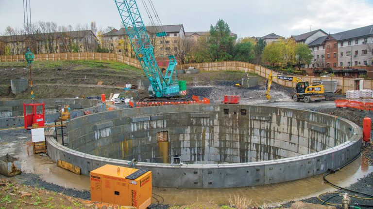
Parallel shaft construction using one crane – Courtesy of SNS
Conclusion
At the time of writing (May 2016) the Elmvale Row shaft construction is nearly complete with roof slabs in place and construction is 20 weeks ahead of the original programme. Remaining work includes the mechanical and electrical fit out associated with the screening, pumping and vacuum equipment, site finishing including placement of capping soils to mitigate any residual contaminates and landscaping. The planned completion date is October 2016.
The current out-turn project cost forecast is £10m versus a target price of £11.1m. The project has benefited from close engagement with the local community and been very interactive with the Elmvale Primary School, meeting all requests from the school to ensure minimal impact and providing learning opportunities about the project with an emphasis on the importance of staying safe when walking or playing near construction sites and machinery.
Once completed the project will be visible only as renewed parkland but will reduce significant flooding of Elmvale Row and the negative impacts on 24 properties.
The project demonstrates innovation through integrated delivery and collaboration with the local community, a true reflection of Scottish Water’s commitment to customers.


