Glenlatterach WTW (2019)
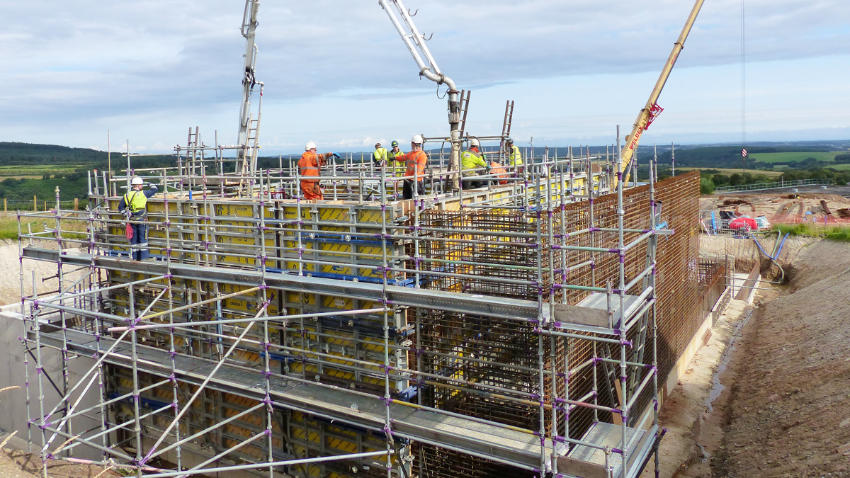
RGF 1 & 2 wall pours looking north - Courtesy of ESD
Located south of the town of Elgin in the north east of Scotland, Scottish Water’s Glenlatterach WTW is situated in the heart of Speyside, home to some of Scotland’s most beautiful scenery as well as roughly half of all of the whisky distilleries operating in Scotland. Raw water is abstracted from the Glenlatterach Reservoir and the water treatment works has a maximum output of 11.4 Ml per day, supplying treated water to Elgin, Forres, Dallas, Lossiemouth and Kinloss.
Current treatment works operation
Glenlatterach WTW is a traditional clarification and pressure filtration plant with inlet minimum, average and maximum flow rates of 50, 100, 132 l/s respectively. Raw water is fed from the draw off tower at Glenlatterach Reservoir. From there it flows, under gravity to the inlet works at the site. The raw water is dosed with lime for pH correction and then aluminium sulphate for coagulation before passing through 4 (No.) underground in-pipe flocculation units. The conditioned water is then dosed with polyelectrolyte to enhance coagulation prior to entering 5 (No.) sludge blanket clarifiers.
After the clarifiers the water is dosed with lime to readjust the pH to an optimum level for oxidisation. Sodium hypochlorite is added as the oxidising agent for the manganese. The oxidised manganese is then removed along with any remaining floc from the clarifiers by 22 (No.) pressurised sand filters. The natural gradient of the site provides enough hydrostatic head across the pressurised filters.
Following the pressure filters sodium hypochlorite is dosed prior to the chlorine contact tank for final disinfection. After the chlorine contact tank orthophosphoric acid is dosed for plumbosolvency control, ammonium sulphate is then dosed to achieve chloramination and lime for final pH correction. Treated water flows to three clear water storage tanks before entering distribution.
Sludge from the settlement tanks (clarifiers), pressure filter backwash and instrument waste are fed to the 4 (No.) sludge holding tanks prior to entering the public sewer for treatment at the Elgin WwTW.
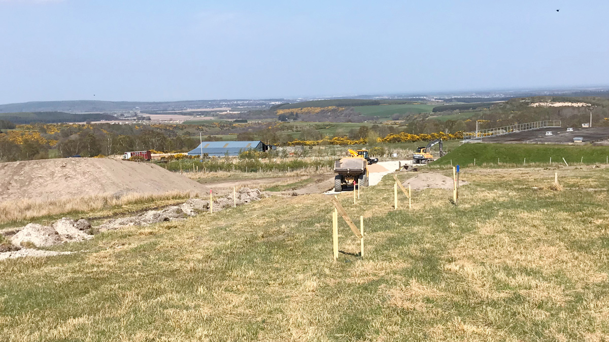
RGF bulk excavation in progress – Courtesy of ESD
Project objectives
As part of their current SR15 Investment Programme, Scottish Water decided to upgrade and improve the treatment works at Glenlatterach to achieve the following key objectives:
- Provision of a more robust treatment process to deal with the significant seasonal variations in water quality.
- Upgrade the control of the chemical dosing equipment on site to ensure optimal coagulation is achieved to manage the seasonal water quality variations.
- Enhance resilience by upgrading the existing back-up power generator to the latest standards ensuring seamless switching between the mains and the generator in the event of a power outage. This needed to be carried out while avoiding disrupting the process in turn ensuring a constant supply of drinking water entering supply.
Following the identification of the project objectives a feasibility study was undertaken by Scottish Water to ascertain the optimal process solution which would achieve these needs while working within the constraints of the existing plant. The recommendations from this study were to introduce a 2-stage filtration process as described below:
- Stage 1 filtration: Organic removal.
- Stage 2 filtration: Oxidised manganese removal.
This 2-stage approach would also allow better coagulation control and offer improved aluminium compliance as secondary benefits.
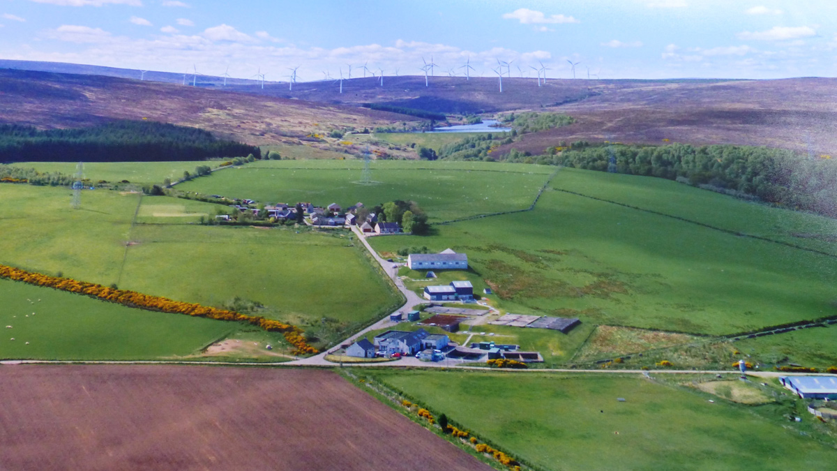
Aerial view of the existing WTW – Courtesy of ESD
Project delivery
The outline design, detailed design and construction of the upgrade to Glenlatterach WTW was allocated by Scottish Water to their Non-Infrastructure Alliance Partner Efficient Service Delivery (ESD); a joint venture made up of MWH Treatment, Binnies and Galliford Try. ESD work in close collaboration with Scottish Water and their framework suppliers to deliver the Non-Infrastructure programme. A summary of the key contributors to the Glenlatterach project is detailed in the table below.
- Principal designer & contractor: ESD JV
- Filter nozzle plenum floor: Cadar Ltd
- Centrigual pumps: SPX
- Penstocks: Industrial Penstocks
- MCC/systems integration: MCS Control Systems
- Standby generator: Dieselec
- Filter sand supplier: Western Carbons Ltd
- Earthworks contractor: Billy Miller Plant Contractors
- Concrete supplier: Breedon
- Formwork, rebar & concrete contractor: DB Stuart Ltd
- Steelwork & cladding contractor: Metalwork UK
- Building works & mechanical installation contractor: AJ Engineering & Construction Services Ltd
- Electrical installation contractor: Aird Walker Ralston Ltd
- Safety showers & eyebaths: Aqua Safety Showers International Ltd
Digital delivery
The detailed design for the project was undertaken by ESD’s regional design team based in Salford. The project is making extensive use of the latest digital delivery techniques including BIM and other associated technology including:
- The development of Intelligent P&ID’s.
- 3D laser scanning and conversion to a 3D base model.
- The production of a 3D model with 2D ‘for construction cuts’.
- Use of BIM Field and Glue to ensure designers, suppliers and the construction team are all working in a collaborative fashion, real-time using the same current information.
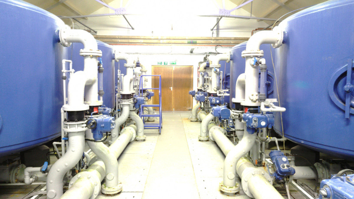
Laser scan of existing filter hall at Glenlatterach WTW – Courtesy of ESD
Detailed design development using digital delivery
The project consisted of three main elements of work:
- New build rapid gravity filters located in a new plant building.
- Upgrading/modernisation of the existing pressure filters to act as a manganese removal stage.
- New wastewater holding tanks.
Due to the complexity of working in the existing pressure filter building the project team, in conjunction with Scottish Water, decided to deliver the project using Digital 3D modelling. The development of the design commenced with carrying out a 3D laser scan of the existing works.
The entire site was laser scanned including the inside of all existing structures where work was to be undertaken. Using the latest technology delivers multiple benefits including accurate replication of the site and reduced costs, with associated H&S benefits, through fewer numbers of site visits.
The scan was initially converted into a digital format where it could be viewed by any interested party through Autodesk ReCap. This was an enormous help to the designers, construction team and Scottish Water as at any design reviews they could carry out a virtual walk through of the existing works in 3D and confirm the smallest site details all from their desks. This was of particular benefit when considering existing filter building, which is already very congested with pressure vessels, pipework, valves, cable tray, panels instruments all of which could be exactly located, inspected and measured at any time and revisited as many times as needed.
A ground penetrating radar (GPR) survey was undertaken to locate underground services across the site. The output from the survey was compared against as-built records and public utility company information relevant to the site. All these sources of information were incorporated into the 3D model to present as complete a picture of the underground services as possible. Benefits here were to prevent injury to staff due to a service strike or accidental damage of services which in turn could potentially interrupt the operation of the existing works.
The Intelligent P&IDs were created in the software package OpenPlant. Intelligent P&IDs allow design information to be embedded within the drawings and facilitate collaborative working by each of engineering disciplines by providing a common shared platform from which to operate. Using the Intelligent P&IDs as the common platform each of the discipline engineers were able to create key engineering deliverables including load schedules, single line diagrams and plant and equipment schedules.
3D model development
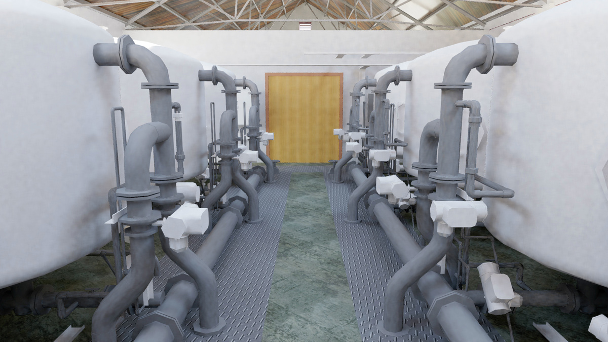
3D model created from the 3D scan – Courtesy of ESD
A 3D design model was produced in Revit using the output from the laser survey to replicate the existing works digitally. The initial model of the entire site was developed to a relatively low level of detail but as the design progressed, the design team identified the areas where a higher level of detail was required.
Data from the scan was introduced to provide this higher level of definition. This was particularly useful when designing interfaces with the existing works.
The model of the new works was developed in the level of detail (LOD) sequence below:
- LOD 100: The model element may be graphically represented in the model with a symbol or other generic representation.
- LOD 200: The model element is graphically represented within the model as a generic system, object, or assembly with approximate quantities, size, shape, location, and orientation.
- LOD 300: The model element is graphically represented within the model as a specific system, object, or assembly in terms of quantity, size, shape, location, and orientation.
- LOD 400: The model element is graphically represented within the model as a specific system, object or assembly in terms of size, shape, location, quantity, and orientation with detailing, fabrication, assembly, and installation information.
- LOD 500: The model element is a field verified representation in terms of size, shape, location, quantity, and orientation. Non-graphic information may also be attached to the model elements.
As the 3D Revit model developed to include the new works and supplier’s information, equipment tag numbers and relevant metadata were incorporated allowing easy identification of the project components and their physical location within the water treatment plant.
The 3D model was shared with subcontractors and suppliers, facilitating collaborative working with mechanical and electrical installation subcontractors able to efficiently locate relative plant and equipment avoiding rework through clashes on site. Embedding key metadata in the model will also provide great benefit during the testing and commissioning phases.
New rapid gravity filters
The new primary filtration stage was to be integrated into the existing treatment process after the clarification stage but before the pH correction and disinfection stages. A bypass around the new primary filtration plant was also to be provided. The primary filtration stage is designed to operate at maximum throughput of 11.4 Ml/ day with one filter in backwash mode and one unit out of service for cleaning or maintenance. The primary filtration plant consisted of 4 (No.) rapid gravity filters (RGF).
The RGF filters are contained within a portal frame building consisting of half height blockwork walls, the upper walls and roof are double skinned, insulated with a steel profile cladding. The filters themselves form part of the concrete sub-structure for the main plant building. A Cadar in situ filter floor was selected as the preferred solution for the filter backwashing arrangement. The filters will be backwashed using a combined air/water filter backwash system.
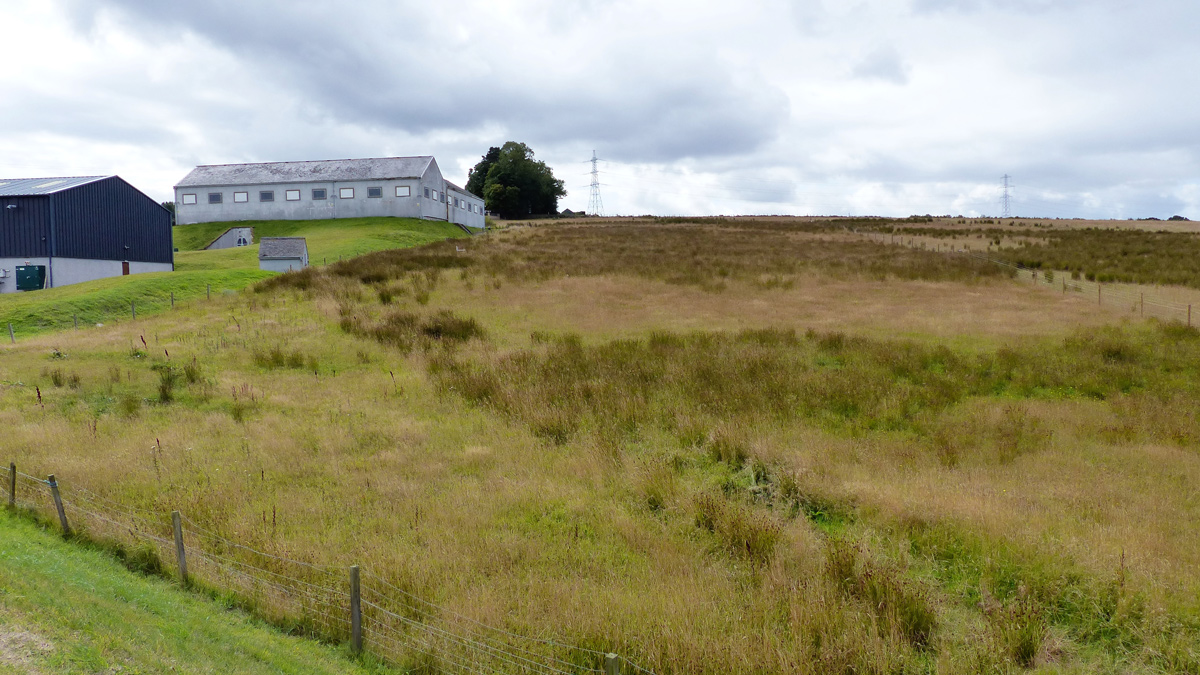
RGF building area prior to excavation – Courtesy of ESD
The addition of the new RGF plant, between the existing clarifiers and the chemical dosing, meant that the available hydrostatic head as the flow enters the re-configured pressure filters is reduced. This created the need for new interstage pumps to ensure that full flow to treatment could be achieved through the pressure filters under all operating conditions. These pumps were designed to only operated under certain flow conditions favouring gravity operation whenever this mode of operation was available. Operating costs for the works were reduced by designing the plant to operate in both modes.
Modification works to the existing primary pressure filter
There are 22 (No.) existing pressure filters arranged in two banks of six and two banks of five, twelve of which are to be refurbished and upgraded to provide secondary filtration with the objective of removing manganese. As the full extent of the refurbishment requirements cannot be identified until each pressure filter is taken out of service and inspected, a preliminary scope of works was agreed with Scottish Water which will be subject to confirmation during the implementation phase.
Raw water inlet headers, filtered water outlet and backwash manifolds needed to be changed to accommodate the higher flows created by reducing the number of in service pressure filters from the original twenty-two to twelve.
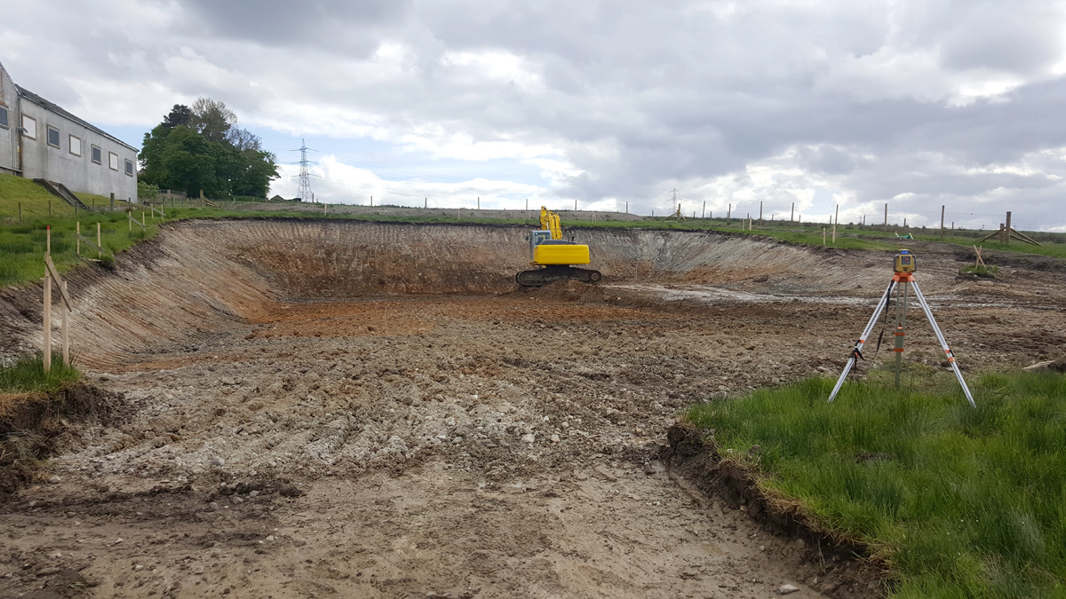
RGF building bulk excavation – Courtesy of ESD
Wastewater holding tanks and standby power generation
As part of the planned enhancements to the plant, there was a requirement to modify and refurbish the existing sludge holding tanks, which will be re-purposed as wastewater holding tanks to attenuate all the waste flows before discharge via the sewer to Elgin WwTW. Each tank is to be designated to a duty as described below:
- One tank will be used to contain all existing plant overflows except for the overflows and drain down from the chlorine contact tank and the 3 (No.) clear water storage tanks.
- Two tanks will be used to store wastewater including clarifier sludge, RGF dirty backwash and pressure filter backwash.
- One tank will contain and store chemical waste products.
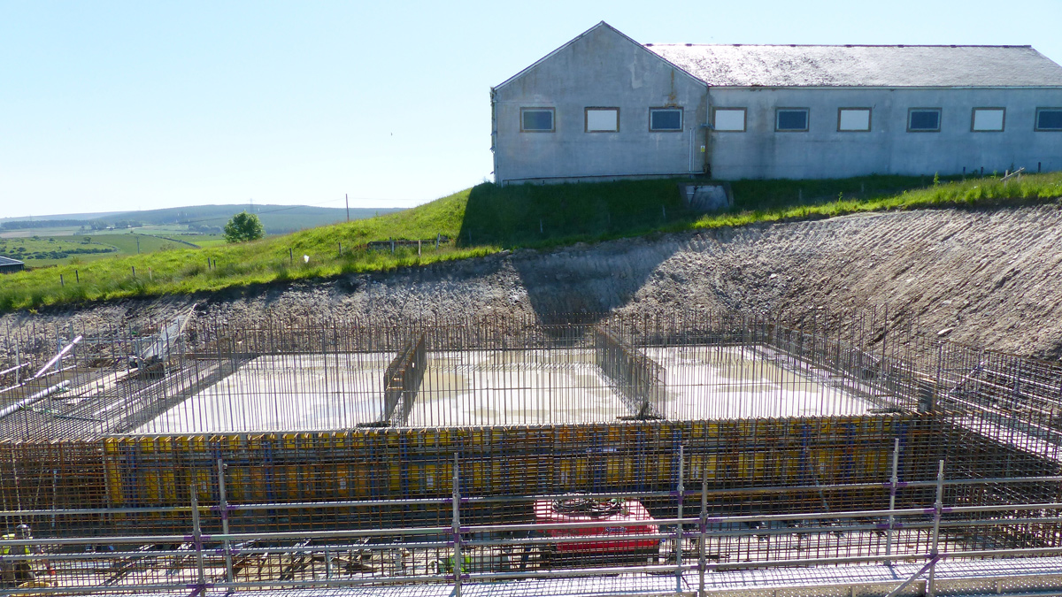
RGF bases – Courtesy of ESD
Working in the digital space
As all design work was carried out in the 3D digital space, no paper copies of drawings were produced until the engagement with the supply chain. All third-party design elements were produced in 3D and federated into the model, allowing early clash prevention and detection. The model was regularly reviewed by all disciplines concerned during the weekly design review meetings and proved invaluable in project review meetings with the key stakeholders from Scottish Water. The use of these digital tools significantly reduced the time for HAZOP and access, lifting and maintenance (ALM) studies where problems could be considered and resolved in the virtual world.
As the project moves into the construction phase the use of BIM field will allow the site team to view the 3D model on site, using tablets, at any time. Any site queries can be quickly addressed using this software facilitating close collaboration between the design and construction teams. All technical queries and responses are archived for future reference thus providing an auditable record of all design changes.
Project status
Design started in January 2018 and on-site construction in April 2019. The project is due to complete in July 2020.


