

Guildford STW (2023)
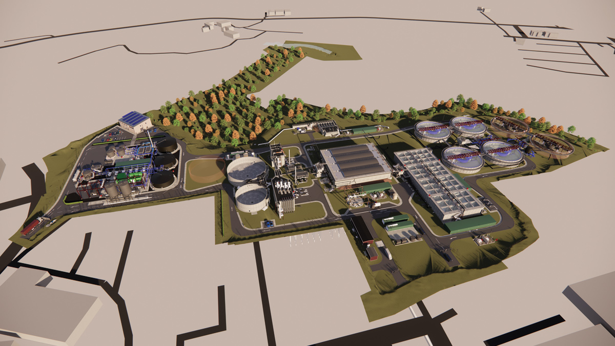
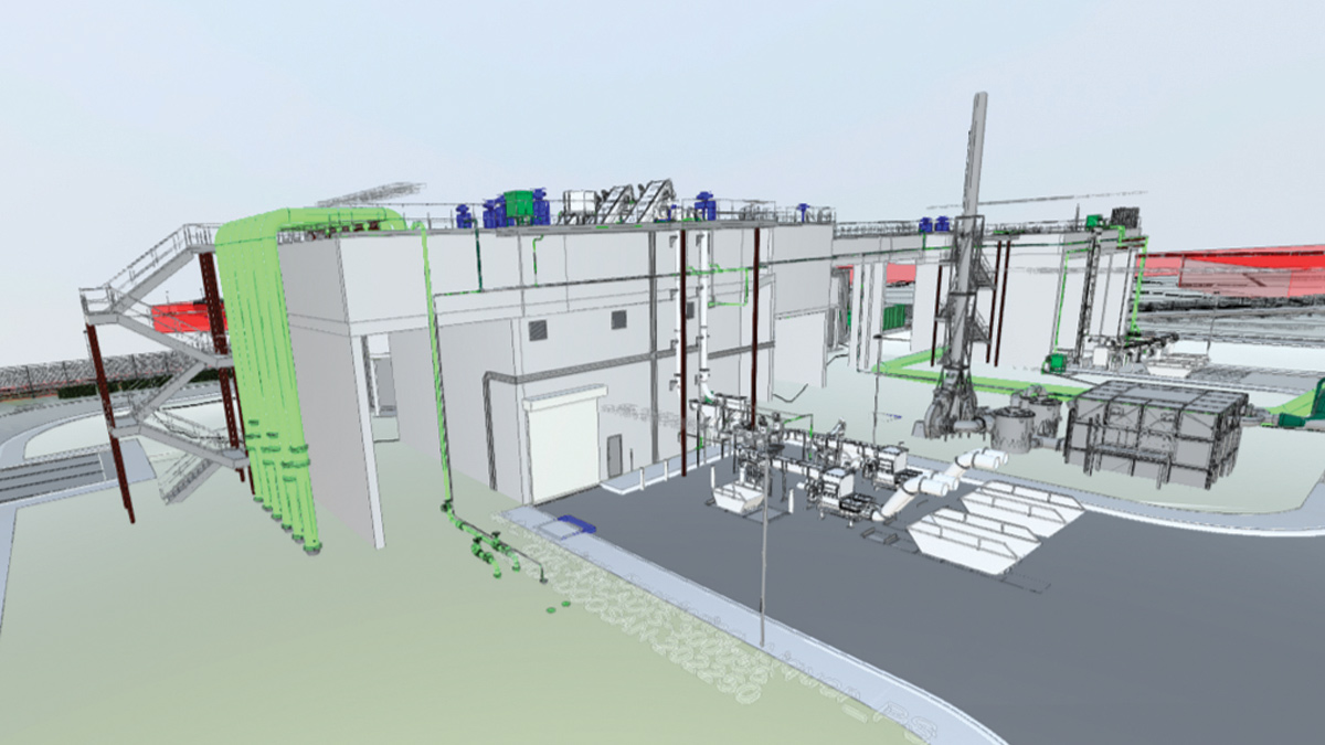
Site overview: BIM model of new Guildford STW - Courtesy of BAM Enpure JV
Guildford Borough Council (GBC) are progressing with the development of approximately 41 hectares of brownfield land located along the west bank of the River Wey as it runs through central Guildford and north through Slyfield Industrial Estate. Guildford Sewage Treatment Works (STW) lies within this land and requires relocation in order to enable the development to proceed. This relocation forms a critical part of the Slyfield Area Regeneration Project, and will allow the delivery of up to 1,550 new homes, partially on land occupied by the existing STW, to enable local housing needs to be met.
The new sewage treatment works will be built to the north of Slyfield Industrial Estate on land that has been used for quarrying, and in turn used as a landfill site, and is currently largely unused. In addition to the construction of a new works, relocation of the works to this location will require the construction of a new transfer tunnel to divert existing incoming flows to the new site, and the construction of a new outfall to the River Wey. The existing STW must also be decommissioned to enable use by the Weyside Urban Village (WUV) Development.
Design flows
The new Guildford STW is designed for a population equivalent (PE) of 125,300, with room to expand the site in the future.
| Design criteria | Flow rate |
| Dry weather flow (DWF) | 322 l/s |
| Average flow | 368 l/s |
| Flow to full treatment (FtFT) | 746 l/s |
| IPS peak capacity | 2,250 l/s |
Location of new works
The site was formerly quarried for sand and gravel during the 1960s and 1970s, with the resultant voids filled with waste materials progressively moving from west to east (i.e., towards the River Wey), which continued until the late 1980s. There is no record relating to the exact nature of the fill materials. The site was understood to have taken household and commercial wastes, but not special or difficult wastes. Following this, the site has remained vacant and undeveloped.
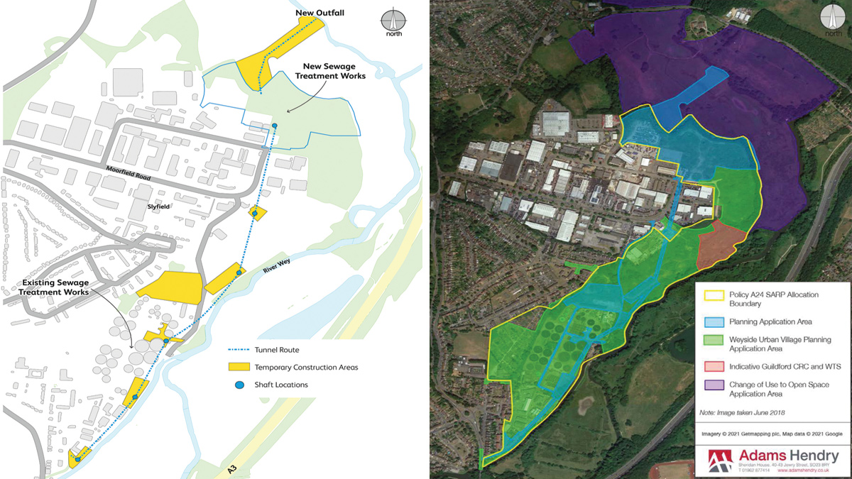
(left) Location of new sewage treatment works and tunnel route and (right) Slyfield Regeneration Project area – Courtesy of Adams Hendry
Transfer tunnel
The STW transfer tunnel will consist of a 1.4km long, 1500mm internal diameter, 1780mm outer diameter tunnel, made of precast concrete pipe, which will be installed by pipejacking (microtunnelling) method. Six shafts are required to facilitate its construction and will serve as temporary launch and reception shafts. Network modelling by Arcadis verified the designed flow velocities remain self-cleansing and provide for the flow rates required.
A geotechnical interpretive report has been prepared in review of the ground conditions for the scheme as whole, and to ascertain suitability for shaft sinking and tunnelling. The principal geological stratification for the site consists of Made Ground overlain principally with River Terrace Deposits, with sections of overlapping Alluvium, overlaying the solid geology of firm to very stiff clay of the London Clay Formation (LCF).
The selected method of microtunnelling was chosen as it allows long pipeline sections to built, and its suitability to the ground conditions within LCF at Guildford, while limiting the exposure to personnel to underground works, against traditional methods. The microtunnelling is operated from a central control cabin at ground level, and only limited personnel access into the tunnel is required to service the microtunnel boring machine during construction.
A ground movement assessment has been prepared and modelled using XDisp software by Oasys. The analysis constitutive model is based on the O’Riley & New method. The method predicts ground movements resulting from ground loss which produces strain of the soil within the influence zone, and projects the settlement in a gaussian distribution curve.
Ground improvement & remediation
The project team has consolidated decades of site investigation data into a unified format and 3D model. The process involves first combining data within OpenGround software and applying scripted translation to a common description – for example having all London Clay called ‘London Clay’, rather than ‘LC’ or ‘Clay’.
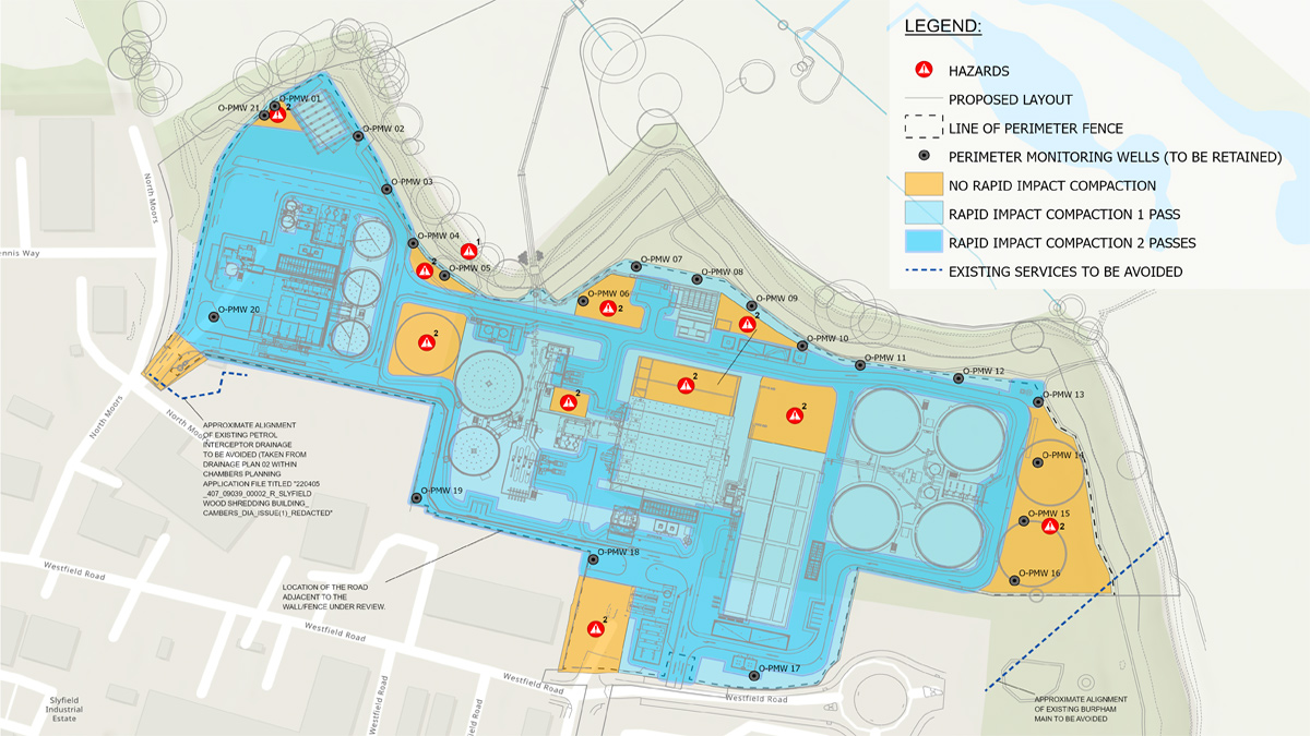
RIC 1 and 2 pass areas – Courtesy of BAM Enpure Ltd JV
This combined dataset is then used in Leapfrog 3D geological modelling software, which applies intelligent interpolations, and highlights anomalies that can be quickly assessed and removed. The resultant 3D model has then been used to enhance communication in the engineering AutoDesk BIM 360 federated models, and in the proprietary Arcadis SmartAtlas GIS viewer.
Rapid Impact Compaction (RIC) is a method of imparting energy to the ground using a repeated but relatively short drop-weight, where a base plate (or “puck”) is in constant contact with the ground. RIC is preferred over a larger drop-weight technique due to its more progressive and less disturbing impact on the ground it is being used on. The method is also faster and uses smaller scale setups. A challenge for the RIC method was whether the energy it imparts is sufficient to densify the ground, versus other higher energy drop-weight methods. A trial was deemed necessary to demonstrate the suitability of this method. RIC is proposed to be applied over the majority of the site with an expected densification of landfill down to approximately 4.5m. Areas where assets will not be supported on driven full depth piles will undertake a second pass of the RIC method, reducing the long-term settlement of the landfill material. The predicted reduced surface will be levelled as required by the infill of depressions with imported stone or other suitable material.
Improvement of the existing ground by reinforcement through installation of Vertical Rigid Inclusions (VRI) method across the site. Supporting of level sensitive and heavier elements will be on precast driven piles founded below the landfill material. The combination of methods will be designed to achieve Thames Water’s settlement performance values over 40 years, and remain within the allowable values of 50mm and 100mm. This will reduce the need for full depth driven piling which would otherwise be required.
Reduction of infiltration to the landfill materials by ensuring impermeable surfaces drain to the treatment works and are released at the outfall away from the site. Gas and leachate well monitoring is provided along the perimeter of the site to monitor any impact and provide leachate removal points if required.
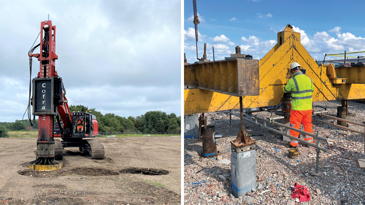
(left) Rapid impact compaction rig and (right) pile under test – Courtesy of BAM Enpure Ltd JV
Guildford STW Relocation Project: Supply chain – key participants
- Client: Thames Water
- Principal contractor & designer: BAM Enpure Ltd JV
- Client designer: Jacobs
- Civil designer: Arcadis
- Planning consultant: Adams Hendry Consulting Ltd
- Process & M&E: Enpure Ltd
- CFD analysis: The Fluid Group
- Physical modelling: Hydrotec Consultants Ltd
- Tunnel design: Joseph Gallagher Ltd
- Temporary works/shoring: MGF Ltd
- Precast structures: A-Consult Ltd
- Precast structures: FLI Precast Solutions
- Rapid impact compaction: Cofra Ltd
- Piling: Aarsleff Ground Engineering Ltd
- XDisp software: Oasys
- Controlled modulus columns: Vibro Menard Ltd
- Inlet works and PST odour covers: Power Plastics Ltd
- Inlet pumps: Grundfos
- Imported sludge Strainpress: Huber Technology
- Escalator screens: Longwood Engineering Company Ltd
- Grit removal plant: Jacopa
- PST scrapers: Colloide
- FST scrapers: Purac AB
- Odour control plant: Odour Services International Ltd
- FBDA grids and blowers: Xylem Water Solutions
- Sludge thickening & dewatering: Kent Stainless Ltd
- Cake Silo: Saxlund International
- Cloth pile filters: Eliquo Hydrok Ltd
- Polymer batching & dosing: Richard Alan Engineering
- Ferric plant: Colloide
- Tank logging system (WASP): JR Pridham Services Ltd
- Glass lined steel tanks: Balmoral Tanks Ltd
- Sludge tank mixing: Landia UK Ltd
- Pumps, mixers & flocculators: NOV
- Welfare building: M-AR Limited
Guildford STW – the new sewage treatment works
Inlet pumping station
The new STW is being designed to maintain inflow from the external catchment ranging from dry weather to 1 in 100-year storm (plus climate change allowance) with future-proofing beyond the 2041 design horizon.
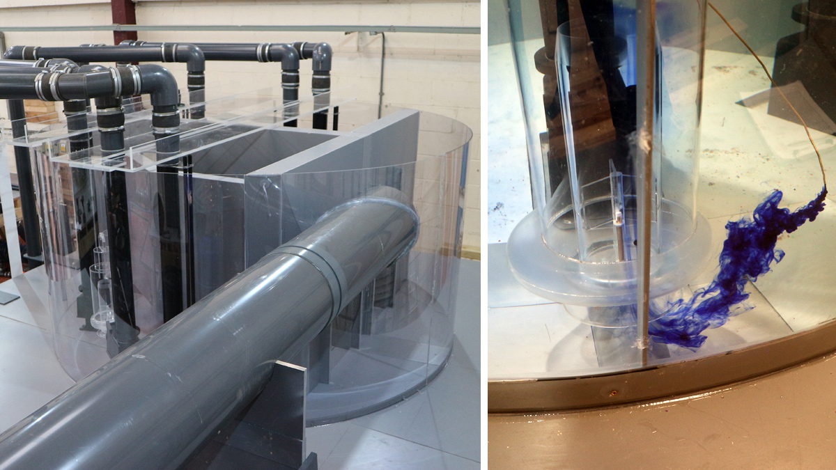
(left) inlet pumping station physical model and (right) inlet pump testing physical model – Courtesy of Hydrotec Consultants Ltd
The pump design has been developed to fulfil the project brief load requirements (future peak IPS capacity 2585l/s) and some flexibility either side of the requirements is available due to the standard capacity equipment design offered from the supply chain.
The proposed arrangement now consists of a wet well 12.5m diameter, approximately 20m deep. A common inlet will be provided to dissipate any entrained air, and two selectable pumped sections with double isolation will be provided by wall mounted penstocks on full height walls.
The pumping well will be constructed in two halves, hydraulically connected in normal operational mode however each half will be able to be isolated (using motorised penstocks) in accordance with specification requirements surrounding double isolation, to allow person entry into half of the wet well at a time.
Each half of the wet well will have three pumps installed giving a capability to provide full flow to treatment from two pumps with a standby permanently installed.
The pumping station was first modelled by computational fluid dynamics (CFD) to demonstrate the assumed flow patterns that will occur. The pumping station was then physically modelled to comply with the specification and process design requirements particularly with respect to distribution, mixing, settlement, turbulence, dispersion, and freeboard for the full range of flows that each structure is expected to receive.
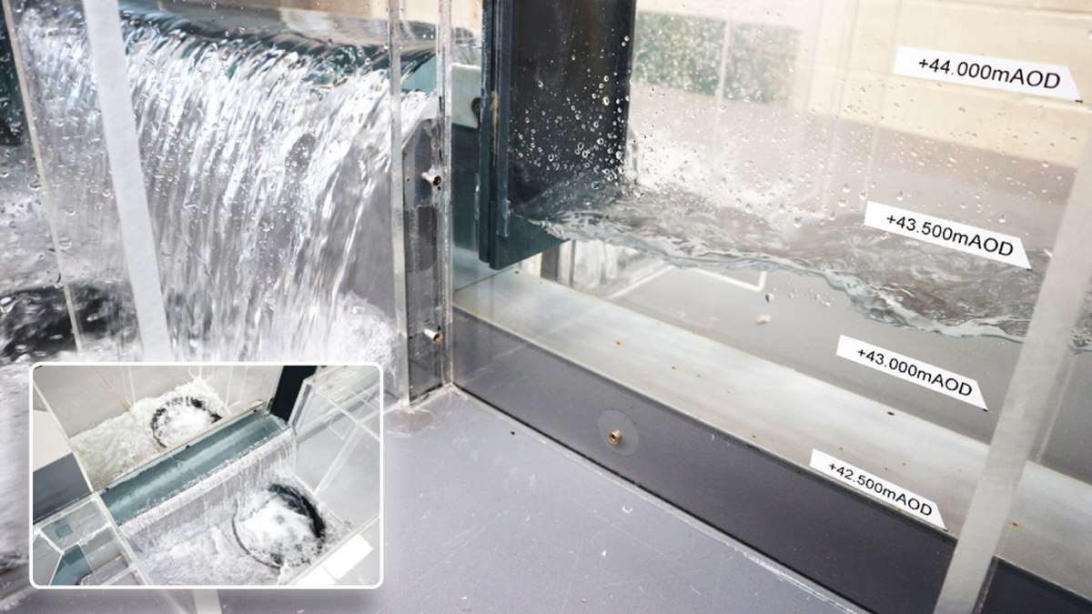
Storm overflow physical models – Courtesy of Hydrotec Consultants Ltd
Inlet works
The inlet works is being designed to receive all pumped flows from the inlet pumping station (including future peak IPS capacity 2585 l/s), inlet works drainage and screening liquor return flows. Flows will enter the inlet works and then separate across the four escalator screens inclined at an angle of 45°. Each screen will be provided with a local proprietary control panel. Each panel will incorporate a differential ultrasonic level control.
An emergency bypass will be provided upstream of the screens to accommodate all four screens blinding at the same time. Three 1200mm wide duty screens will be required to screen flows from low flow up to 2585 l/s, screening 6mm in two directions.
The inlet works and grit treatment plant will be covered with odour covers which will be connected to the inlet works and PST odour plant. The inlet works has been classified as a Zone 2 Area under the odour covers and all equipment beneath the odour covers will be ATEX rated.
Storm tanks
Storm flows from the inlet work storm separation chamber will flow into two storm tanks via a 1400mm above-ground pipe. Within the 1400mm pipe between the storm separation chamber and the storm tanks there will be a partial pipe MCERTs certified flow meter to measure the total flow into the storm tanks.
During normal operation the blind tank will fill first, then the spill tank will fill. In the event that both tanks are full to capacity (and still in storm flows) the spill tank will overflow via a weir and the storm tank will discharge to river.
Elevated inlet works – Courtesy of BAM Enpure Ltd JV
The storm tanks contents will automatically return to the inlet pumping station via 700mm gravity pipe when the flow being pumped to the inlet works drops below a predetermined set point. The return flows will be controlled to approximately 0.5 DWF via an automated valve controlled by an electromagnetic flow meter located in the gravity main, returning to the common inlet well of the inlet pumping station.
Storm tank cleaning will be a pumped system with the two pumps located external to the storm tanks. Storm tank cleaning will be initiated during the latter part of the storm tanks draining back to the inlet pumping station and will not operate when the tanks are filling. The pump discharge pipe work will include connections for flushing with washwater.
Ferric storage & dosing
Two 45m3 ferric storage tanks will be located in a concrete bund with the dosing skid packages and control system located within an adjacent kiosk. The bund will be capable of containing 110% of the one of the storage tanks plus 10% allowance for rainwater. A drive-in bunded area for chemical deliveries will be provided and an underground chemical interceptor will contain any local spillages, complete with a Castell interlocked 3-way valve to allow the bunded drainage area either to drain into the interceptor (during a chemical delivery) or to drain into the site drainage (normal operation).
Chemical dosing points will be provided upstream of the PSTs, on the common outlet channel of the ASP, and upstream of the tertiary treatment plant. The dosing points will utilise sparge systems to ensure adequate distribution of chemicals into the channels.
Odour control plant
The odour plant is a 2-stage system. Stage 2 filters will discharge into an 18-metre-high odour stack. The plant has been designed to achieve a minimum removal efficiency of 98% of H2S and 99% removal of odour, based upon a total system duty of 8432 m3/hr (of which 4813 m3/hr is from the inlet works and 3619 m3/hr from the primary settlement tanks).
Service water
A potable water main supplies a service water break tank via a ballcock (float valve). The service water break tank has a working volume of approximately 30m3 which gives a nominal retention of approximately three hours at average throughput. Service water booster pumps draw water from the tank and transfer it to the service water main network where it feeds the polymer make-up system for all thickeners and dewatering belt presses.
Primary settlement distribution chamber
The distribution chamber has been CFD modelled to calculate the flow split to each downstream primary settlement tank from first principles, and assess whether the proposed design would deliver an equal flow split (+/-5%) for seven future flow scenarios. This required the inlet bellmouth to be turned down to improve flow splitting.
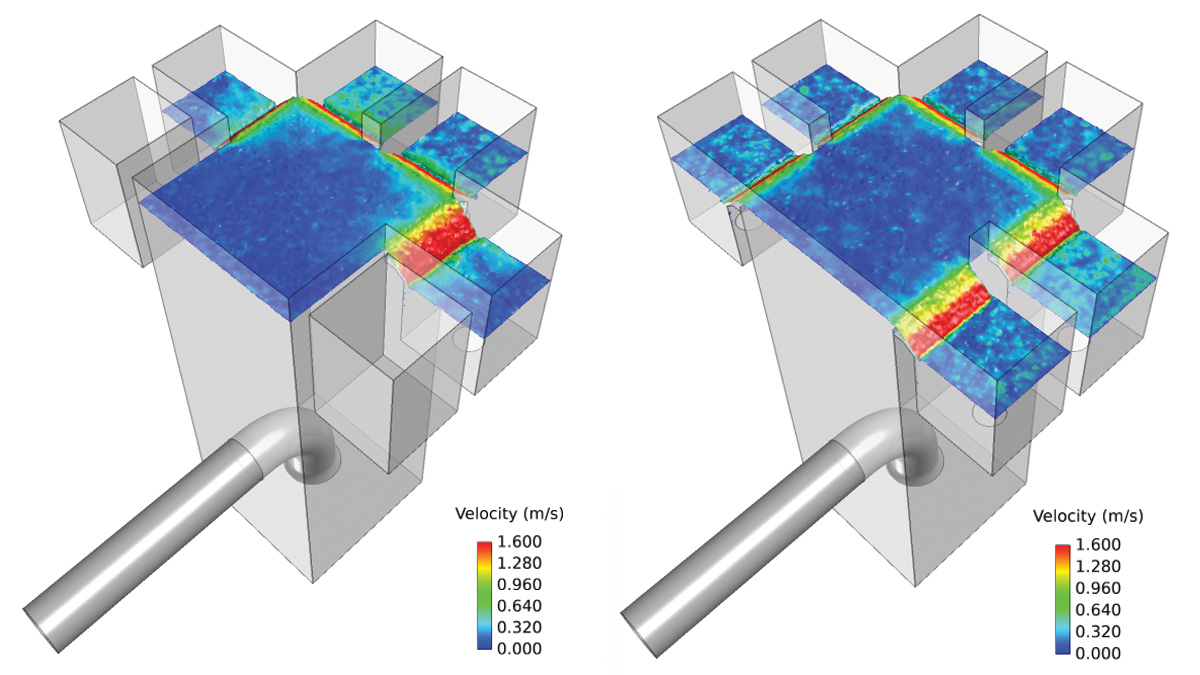
PST distribution chamber CFD models: (left) with four PSTs in service and (right) with six PSTs in service – Courtesy of The Fluid Group
Primary settlement
Primary settlement consists of four 47.15m long by 10m wide tanks, with a depth ranging between 6.24m at the hopper end and 5.3m at the outlet length (equating to 1 in 50 floor slope). Each PST tank has three sludge hoppers at the inlet end. The outlet of the PST discharges into a common 1000mm wide outlet channel. From this outlet channel the 1000mm outlet pipe from the drop box combines with the 700mm RAS lines into an above-ground 1200mm pipe.
Retractable odour covers will be provided across the PST tanks to allow for future inspection, cleaning and maintenance. The odour covers will be connected via ducting to the inlet works/primary settlement tank odour plant. All mechanical equipment installed below the covers will be constructed from 316 stainless steel or high performance plastics. The primary settlement tanks have been classified as a Zone 2 Area, and all electrical equipment beneath the odour covers will be ATEX rated.
The design of the PST Tanks is based upon a maximum inflow of 3022m3/hr to all four in-service tanks, and a peak flow to each tank of 1007m3/hr with one PST out of service. In normal operation all four PST tanks will be in service.
Within each PST tank a chain and flight scraper system will be provided which will utilise high-tech non-metallic materials as the main materials of construction. Scum from the primary tanks will gravitate via a rotating surface skimmer pipe to the above-ground primary settlement scum tank. The primary scum return pumps are progressive cavity pumps, operating in a duty standby configuration. The pumps are fixed speed pumps operating between a high and low level in the scum tank.
The PST sludge hoppers will desludge based upon a SCADA-adjustable interval and duration. The primary desludge pumps are progressive cavity pumps, operating in a duty/standby configuration. The pumps are variable speed pumps operating to maintain a SCADA-adjustable flow set point.
Once the effluent has flowed through each PST it will enter into a common 1000mm wide outlet channel. From this outlet channel flows transfer to the ASP distribution chamber via a drop box and 1000mm above-ground pipe.
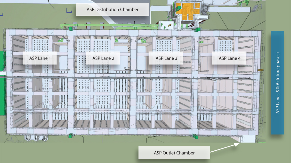
ASP overview – Courtesy of BAM Enpure Ltd JV
Activated sludge plant
The ASP plant will have a distribution chamber using the same general arrangement as the primary settlement distribution chamber.
The activated sludge treatment tank consists of four ASP lanes. Each ASP lane has a selector tank followed by an anoxic zone and then the three aerobic zones. The main aeration lane will be fitted with aeration pipework and fine bubble diffusers. The aeration vessel is 80m long and 6.1m wide with a water depth of 7.05m. The total instantaneous maximum air demand of the ASP is 10,438 m3/h.
The first third of the aerated fraction of each lane will contain 50% of the aeration capacity, the middle third 30%, and the final third 20%. Each aeration lane will have three passes, arranged as channels of 6.15m width. The air for the diffuser grids will be supplied from three ASP air blowers operating on a duty/assist/standby basis. The aeration system will be controlled by an ammonia based real time control (RTC) system utilising a feed forward ammonia load input and a feedback ammonia concentration.
Once the effluent has flowed through each ASP lane it enters into a common 1000mm wide outlet channel. From this outlet channel flows transfer to the FST distribution chamber via a drop box and 1200mm above-ground pipe.
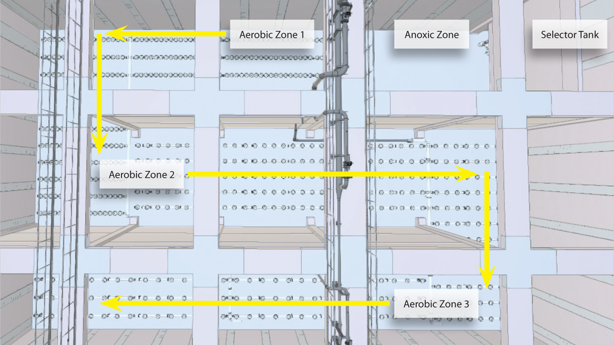
Anoxic and aeration zones flows – Courtesy of BAM Enpure Ltd JV
Final settlement tanks
The FST plant will have a distribution chamber using the same general arrangement as the primary settlement distribution chamber. The four FSTs will consist of 32m diameter flat bottomed circular tanks with a side wall depth of 6.15m. The FST will separate solids from the flow via settlement, producing a clarified effluent which overflows a peripheral weir into a launder channel, before gravitating to the tertiary treatment distribution chamber via a 1000mm below-ground pipe.
The combined clarified outlet flow from the four tanks will be monitored by a common flow meter, as well as suspended solids and phosphorus monitoring instrumentation, all provided on the common line to tertiary treatment.
The design of the FSTs is based upon a maximum inflow to each tank of 1741m3/hr with one FST tank out of service. In normal operation all four FST tanks will be in service. Each tank will have a 700mm inlet pipe, which will flow into a central diffuser drum before entering the FST tank. Each tank features a 600mm outlet pipe fed via a peripheral launder channel, as well as a 400mm RAS gravity outlet pipe. Each of the four tanks features a full bridge rotating scraper system which will run continuously in normal operation.
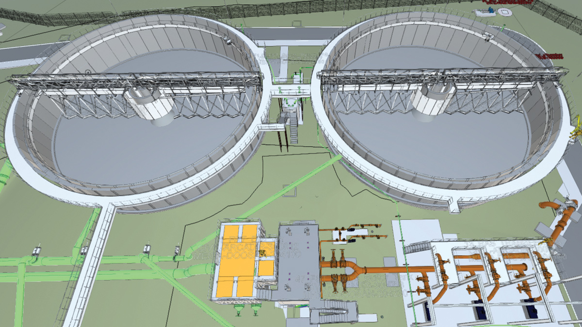
32m final settlement tanks & sludge return (RAS pumping station) – Courtesy of BAM Enpure Ltd JV
Sludge return (RAS/SAS pumping station)
Sludge from each pair of FSTs will enter one of two RAS/SAS desludge chambers. The two chambers will be located side by side and will share a set of three duty/duty/standby RAS transfer pumps, which will recycle the settled sludge from both RAS/SAS desludge chambers to the activated sludge plant distribution chamber feed line.
The variable speed centrifugal RAS transfer pumps will be capable of pumping 2200m3/hr at a maximum head of 8.9mhd. The pumps will operate between high and low level in the duty RAS/SAS desludging chamber, with both chambers provisioned.
A pair of duty/standby SAS pumps is provided, which will facilitate wastage of surplus sludge, with each pump drawing from a single RAS/SAS desludge chamber. The fixed speed centrifugal pumps will transfer sludge to the SAS buffer tank. Control of the SAS pumps will be carried out either on a timer or based on the level in the SAS buffer tank, with the common discharge line featuring flow monitoring.
Tertiary treatment
Clarified effluent flow from the FSTs will pass to the tertiary ferric mixing and flocculation (post-precipitation) stage, where the option will exist to dose ferric sulphate solution into the flow in order to encourage flocculation of remaining solids. This stage will be split into two parallel streams, with flow from the FSTs initially entering via a single bellmouth inlet into a common inlet channel, before passing via twin overflow weirs into two rapid mix chambers, and subsequently overflowing into two flocculation chambers. The design of the rapid mixer chambers will ensure complete mixing (>95% CoV) of chemical in less than 4 seconds.
Flow from the flocculation chambers will weir into a common outlet channel leading to a flow distribution chamber feeding the tertiary treatment stage.
The distribution chamber has been CFD modelled to calculate the flow split to each downstream cloth pile filter from first principles, and assess whether the proposed design would deliver an equal flow split (+/-5%) for seven future flow scenarios.
The tertiary treatment stage will comprise six cloth pile filters, which will operate with all filters in service – however the peak flow will be able to be treated with only five filters in service. The filters will be sized to accommodate a peak flow of 840 l/s, producing a final effluent of 20 mg/l TSS (95%ile) and 0.2mg/l TP (average).
Bypass pipework is to be provided adjacent to the cloth pile filter structure, by which clarified effluent from the FSTs may bypass the tertiary ferric dosing/flocculation and cloth pile filter stage.
Each of the six cloth pile filters will feature a central rotor drum onto which filter discs are attached. The rotor and discs will be fully submerged within the tank, with the discs supporting the physical cloth filter media. Flow entering the filters will flow from outside the discs through the cloth into the discs’ interior, with solids collecting on the external surface of the cloth pile, creating a headloss. As this headloss increases, the water level in the tank will rise and at a pre-set water level (as detected by an ultrasonic level sensor) a cleaning cycle will be initiated.
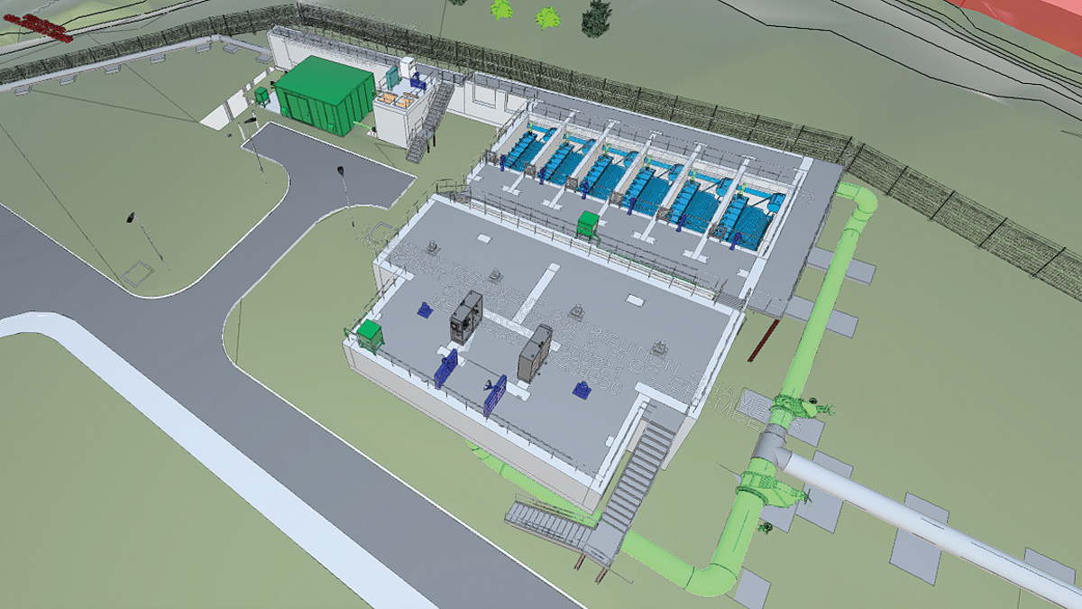
Tertiary treatment flocculation chambers: Eliquo Hydrok Mecana cloth pile filters – Courtesy of BAM Enpure Ltd JV
Filtered final effluent (FFE) from the inside of the filter disc and rotor drum assembly will pass forward through the unit via a low-level aperture to an outlet chamber, from which flow will weir into the common final effluent outfall chamber. An emergency overflow weir is to be provided, allowing unfiltered effluent from the filter tank (external to the discs) to weir over into the outlet chamber.
Backwash liquors from the backwash pumps will exit the filters via a common manifold, draining by gravity to the grit plant liquor PS. Eight backwash pumps will be provided per machine, giving a total of 48 pumps across all six machines. The pumps will be submersible units placed within the tank, with each pump being dedicated to three filter discs. The backwash flow rate is rated for 10 l/s (subject to the installed pipework design/headloss).
Each of the six filter tanks will see some solids settlement occurring (and potential accumulation of other debris), which will create a build-up of sludge in the bottom of the tank. This sludge will be periodically removed by a set of two duty/standby sludge pumps per machine (i.e. 12 sludge pumps installed in total). The discharge from each sludge pump will be connected to the common backwash manifold, leading to the grit plant liquor pumping station.
Final effluent discharge
Flows leaving the cloth pile filters will pass out from the main filter chamber via a low level aperture into a small outlet chamber, from which flows will weir over into the common outfall channel. The final effluent (FE) will flow under gravity through an FE flow measurement flume, with an ultrasonic instrument for measurement of final effluent flows discharged to outfall.
The FE outfall channel will feature a pipe leading to the FE washwater system, with a further line branching off this pipe servings as the suction line for FE Meteorburst Analyser. On exiting the FE outfall channel, flows will enter a dedicated FE outfall main, which will drain by gravity, discharging to the river north of the STW site.
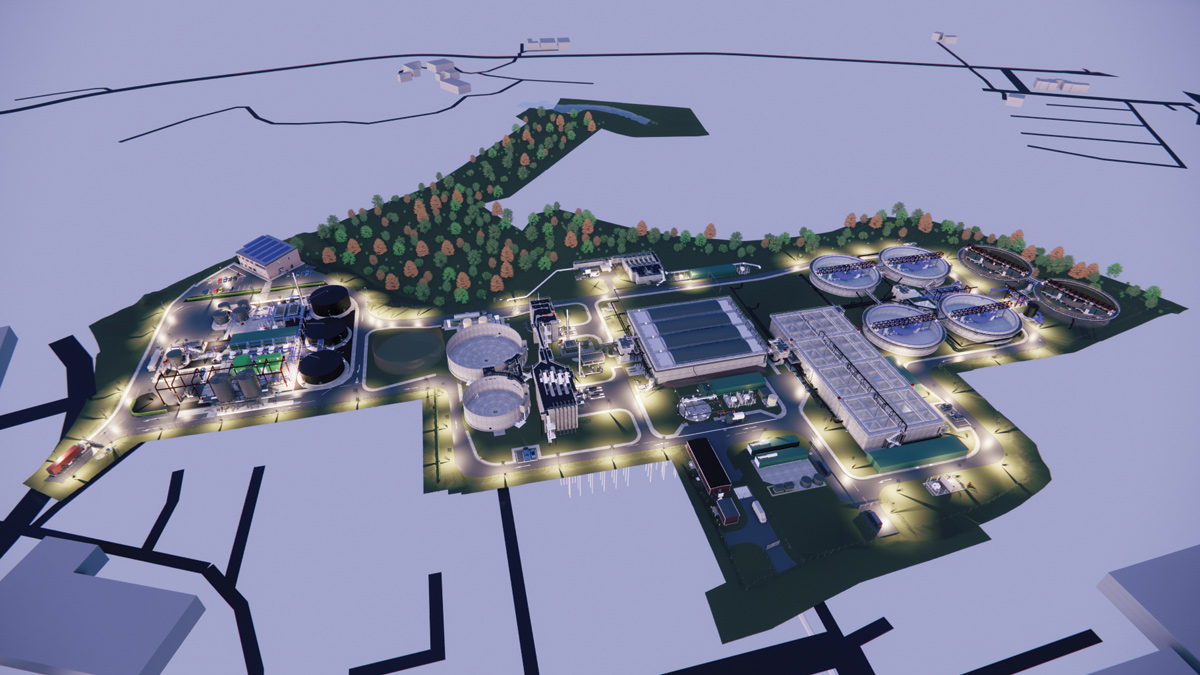
New Guildford STW: 3D model night-time overview – Courtesy of BAM Enpure Ltd JV
Guildford STW – Sludge Treatment Plant
Sludge thickening equipment
Primary sludge from the PSTs will be pumped via the primary sludge pumps to the primary sludge buffer tank, which will have a volume of 120m3 and will be sized to provide 4-hours of intermediate storage prior to thickening.
A set of two duty/standby primary sludge thickener feed pumps will be provided to transfer sludge (at up to 7.0%DS) from the primary sludge buffer tank to the primary sludge gravity belt thickeners.
Two primary sludge gravity belt thickeners (GBTs) will operate in a duty/standby configuration in normal operation, although the streams will be able to run as duty/assist if required. Each machine will be able to handle up to 51m3/h (771 kgDS/h) of primary sludge, at up to 7%DS achieving a solids capture rate of 95%.
Surplus activated sludge (SAS) from the FSTs will be pumped via the SAS pumps to the surplus activated sludge (SAS) buffer tank, which will have a volume of 67m3 and has been sized to provide 4-hours of intermediate storage prior to thickening.
A set of two duty/standby SAS thickener feed pumps will be provided, which will transfer sludge (at up to 2.0% DS) from the SAS buffer tank to the SAS gravity belt thickeners.
Two SAS gravity belt thickeners (GBTs) will operate in a duty/standby configuration in normal operation but will be able to run as duty/assist if required. Each machine is sized to handle up to 55m3/h (332kgDS/h) of SAS, at up to 2%DS, achieving a solids capture rate of 95%.
Sludge balancing/blending tanks
Thickened primary sludge, surplus activated sludge, and screened sludge imports will be pumped to two thickened sludge blending tanks. The tanks will have a combined volume of 2150m3 (1075m3 each), and will be sized to provide a combined total of 4-days retention time prior to dewatering of the blended sludge. The tanks will operate in a duty/standby configuration, with either tank being available for selection as the duty unit for either filling or emptying.
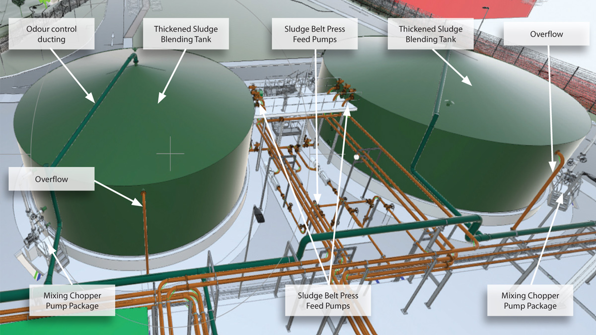
Thickened sludge blending tanks – Courtesy of BAM Enpure Ltd JV
Each tank will feature separate inlet connections for the three types of sludge being received, with actuated valves and crossover lines allowing all sludges to be directed to either of the two tanks. The tanks will also feature outlet actuated valves, which will allow either tank to be isolated from the sludge belt press feed pumps downstream, thereby ensuring the pumps only draw from a single tank at any given time.
A set of three duty/duty/standby sludge belt press feed pumps will be provided, which will transfer blended thickened and imported sludge from the thickened sludge blending tanks to the sludge belt presses. The pumps will be variable speed progressive cavity units, with a peak capacity of 30m3/h (i.e. 15m3/h per pump) at a maximum head of 48.5m, based on sludge of up to 7.0%DS.
Dewatered cake leaving each belt press will enter a discharge cake hopper leading to the suction end of a sludge cake pump. Three pumps will be provided, with a single pump dedicated to a single machine; each pump will operate in conjunction with the associated belt press upstream.
The pumps will be variable speed progressive cavity units, with a peak capacity of 7.4m3/h of sludge (up to 30%DS). The pumps will transfer the cake via individual discharge lines to the sludge cake silos, with manual discharge crossover facilities allowing sludge from the pumps to be directed to either of the two silos as required.
Cake silo storage & discharge
Dewatered sludge cake will be pumped to two truck-loading cake silos, with a combined storage capacity of 600m3, sized to provide 7-days of storage at average cake production. Each silo will feature a discharge screw conveyor (with a sliding frame ‘anti-bridging’ device) which will discharge the cake through a hydraulically operated slide gate valve.
Odour control plant
The odour plant will be a 2-stage system. Stage 2 filters will discharge into an 18-metre-high odour stack.
The plant has been designed to achieve a minimum removal efficiency of 98% of H2S and 99% removal of odour, based upon a total system duty of 6629m3/hr, extracted from the various tanks and thickening/dewatering machines in the sludge plant area.
New STW outfall
Outfall route
The outfall route from the new works site location was assessed thoroughly in the ITN 2 stage of the project’s life and from exiting towards the middle of the works site, proceeds north towards the River Wey. The route deviates initially to minimise any impact on significant trees that exist within the floodplain, and any impact on the band of vegetation around the perimeter of the site.
Final effluent & stormwater pipeline
The final effluent pipeline will be a 750mm diameter pipe. This will be situated above ground from the final effluent channel to the edge of the site, and will be supported by piles when within the treatment works site.
The pipeline then proceeds below ground through the embankment (to be reinstated using clay stanks) and under the adjacent ditch via an inverted siphon arrangement. A jetting/access point will be provided just before the pipeline dives below ground, giving the facility to clean this arrangement and flush from a more direct point than the pipes exit from the final effluent channel. Air relief may also be provided at this point, subject to detailed design.
The storm overflow pipeline will be a 1050mm diameter pipe. This will be situated below ground from the storm tanks to a sampling manhole at the edge of the site; supported by piles when within the treatment works site.
The pipeline will then proceed from the manhole through the embankment (to be reinstated using clay stanks) and under the adjacent ditch via an inverted siphon arrangement. The sampling manhole will provide an ability to clean this arrangement.
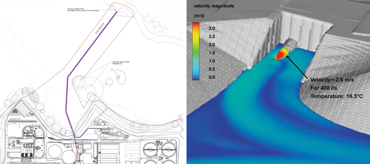
(left) Outfall route plan – Courtesy of Bam Enpure Ltd JV, and (right) outfall low flow scenario CFD model – Courtesy of Arcadis
Outfall structure
The outfall structure will consist of a reinforced concrete headwall, set back from the river channel, to be founded in the river terrace deposits and flared to direct flows downstream and minimise the impact of upstream debris from collecting. The headwall will have duckbill valves on the discharging pipes, and erosion control products utilised in the surrounding area to tie the headwall into the natural riverbank and bed.
The erosion mattress employed following the headwall structure will provide a secondary point at which turbulent flows can dissipate energy without eroding the natural bed of the river.
Where the headwall ties into the natural riverbank, the hard/soft interaction between headwall and natural soil will be reduced by the installation of Rock Rolls erosion control and willow stakes at the base, and the installation of a natural hydro-seeded CocoBN blanket or equivalent (to be seeded with local seed varieties) which will retain the slope shape until vegetation establishes and provides an effective natural erosion control. This will also provide a gradual slope to access down to the river.
Programme
The project obtained planning permission in October 2022, with construction works starting on site in July 2023.
Detailed design of the civil, mechanical and electrical works are due for completion by December 2023. Construction of the works will be complete by August 2025, with commissioning due to commence in from April 2025 through to December 2025. Flows from the existing works will be diverted to the new works from December 2025 (10% flow) in a 7-stage commissioning process with 100% flows diverted to the new STW by March 2026.
Following 100% flow diversion the existing STW will be de-commissioned ready for handover to Guildford Borough Council.