Bicester STW (2022)
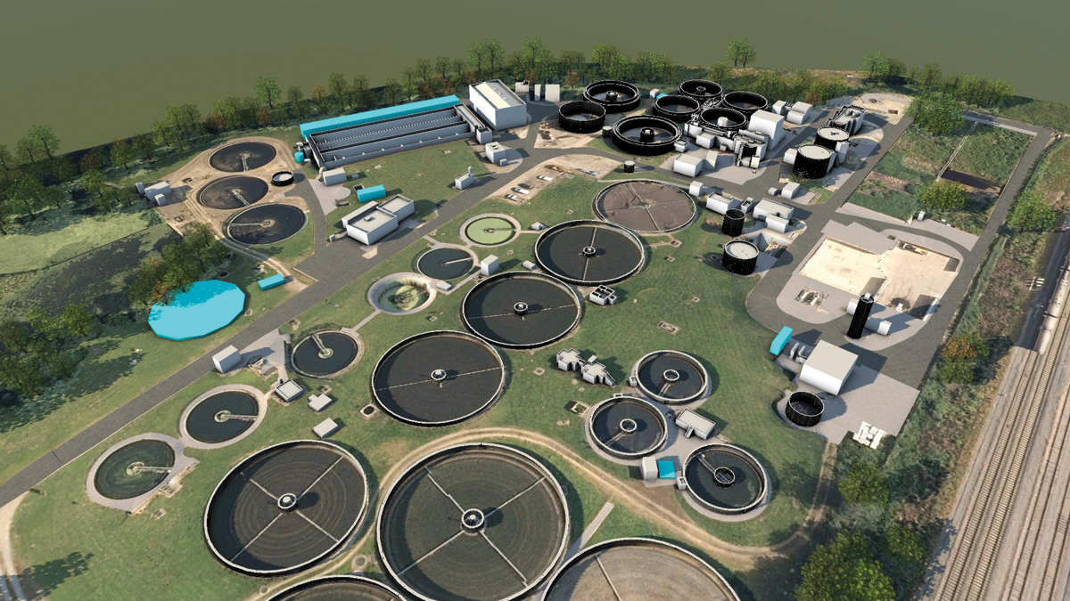
MWH Treatment
In recent years the Oxfordshire town of Bicester had undergone significant growth in its population with a further potential growth of 37% in the near future. In late 2019, Thames Water implemented the need for a growth scheme to upgrade various elements of the works to accommodate the forecast population increase. Bicester STW is a combination of activated sludge plant (ASP) and filter beds with the flow split approximately 75% to the ASP prior to the scheme. The project responded to the requirement to provide treatment capacity for the increase in population equivalent (PE) from 49,500 to 67,840 at the 2026 design horizon. Following a competitive tender process, MWH Treatment was appointed to carry out the detailed design, procurement, construction, commissioning, and testing required to demonstrate that the project had delivered the required outcomes.
Scope of works
The scope of work included improvements to both the effluent and sludge streams, with the core elements being:
Inlet works and primary treatment area
- Increasing the capacity of the chemical (ferric) dosing system including pumps and pipework.
- Improving the resilience of instrumentation on the settled sewage flow downstream of the north PSTs, including replacing the failed in-line flow meter.
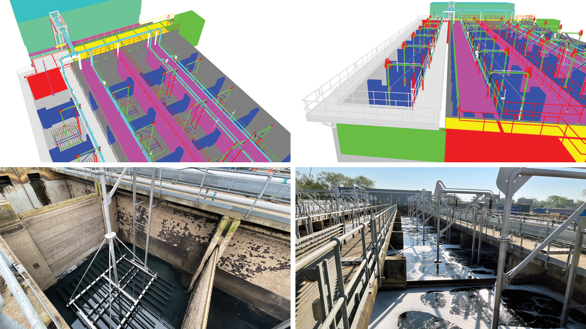
(top left) Extract from 3-D model showing ASP mechanical plant including removable diffuser grids, (top right) extract from 3-D model showing air distribution pipework, (bottom left) New diffuser grids in existing aeration lane and (bottom right) refurbished aeration lane during air test – Courtesy of MWH Treatment
Activated sludge plant
- Construction of a new forth reinforced concrete aeration lane – structurally detached, but hydraulically linked to the existing three lanes.
- Replacement of the existing aeration blowers, air main manifold and motor control centre (MCC) utilising the existing blower building and permanent lifting facilities.
- Replacement of the existing ASP utilities including air distribution pipework and all power and control cabling to the retained plant.
- Incorporation of a most open valve control system as part of the aeration control philosophy.
- Installation of a new above-ground air main from the existing blower house to the existing aeration lanes via a service bridge; also used to carry cables from the new MCC.
- Equipping the new aeration lane with ‘lift-out’ fine-bubble diffusion grids, anoxic zone mixer, aeration pipework, control valves and instrumentation to achieve 3-point DO control. The individual grids allowing a section of diffusers to be removed from service whilst the lane remains live.
- Retrofitting existing Aeration Lanes 1-3 with ‘lift-out’ fine-bubble diffuser grids, aeration pipework, control valves and instrumentation to achieve 3-point DO control.
- New higher capacity return activated sludge (RAS) pumps, pipework and valves.
- Replacement of the existing return activated sludge/surplus activated sludge (SAS) MCC in an independent kiosk together with replacement of power and control cabling to existing plant and equipment.
- An upgrade to the RAS control system such that RAS flow is proportional to ASP inlet flow.
- Replace the existing RAS rising main and flowmeter.
- Modification of the existing aeration lanes outlet chamber to ensure equal distribution of flows to all final settlement tanks (FSTs).
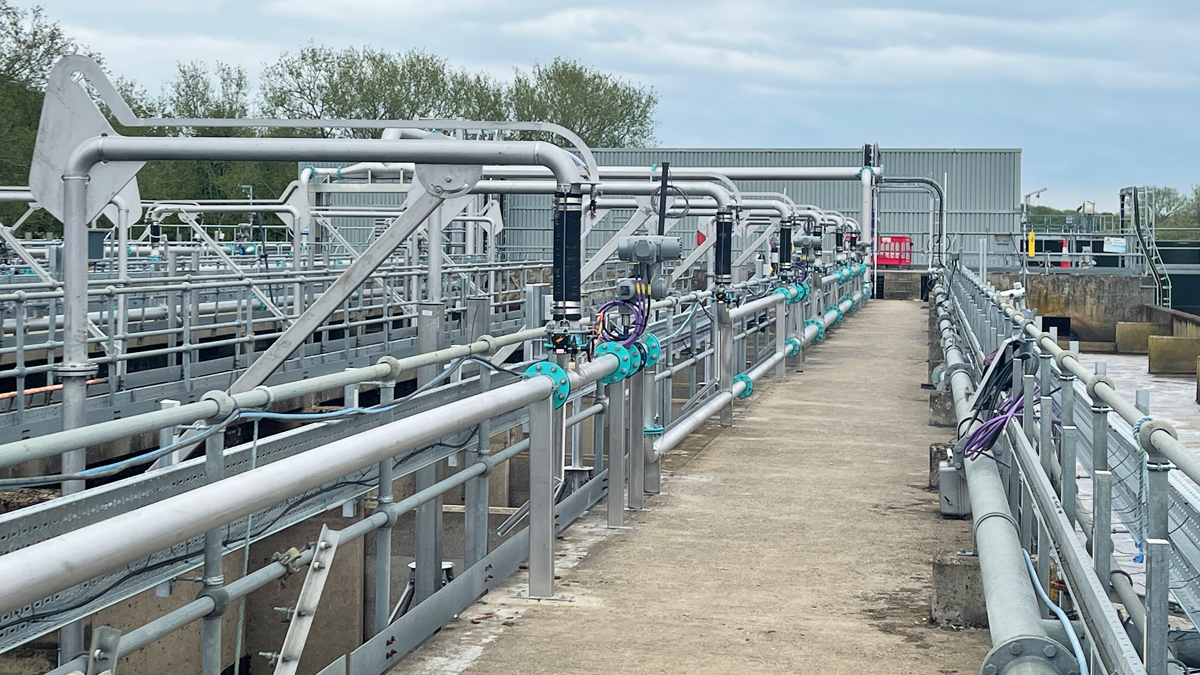
New air distribution pipework to existing ASP – Courtesy of MWHT
Final settlement tank
- Construct a new 20.5m diameter radial flow FST with interconnecting gravity pipework, flow distribution chambers and all ancillary plant and instrumentation.
- Connection of the new FST downstream of the existing filter stream sample point.
- Replacement of diffuser drums to existing FSTs 1, 2 and 3 to current asset standard requirements.
Sludge stream
- Replacement higher capacity de-sludge pumps serving primary settlement tanks (PST) 5-8 and, separately, PST 9 & 10, including replacement of associated field mounted plant, together with power and control cabling from the existing MCC to the pumps and field mounted controls. This required modification of existing starters to accommodate the new pump loads.
- One new standby de-sludge pump for PSTs 9 & 10 including new field mounted equipment, new cabling, new MCC starters, and additional controls for the new and existing pumps.
- One new replacement de-sludge pump for PST 11 including associated field mounted equipment, power and control cabling to the pump and field mounted controls. Provision of new starter and modification of existing starter and controls.
- Provision of a third surplus activated sludge (SAS) drum thickener stream to operate in assist mode, with associated polymer dosing equipment located within the existing building.
Power supply
- Completion of a review of the overall future site power demand to facilitate Thames Water negotiating any necessary revisions to the authorised supply capacity with the district network operator.
ICA
- New site-wide fibre optic ring-main interconnecting the new and existing programmable logic controllers (PLC).
- Modification of the supervisory control and data acquisition (SCADA) and telemetry systems to incorporate the additional plant and other site changes undertaken.
- New PLCs for the RAS/SAS and blower control plus interfaces to legacy PLCs.
Miscellaneous works
- Diversion of existing services affected by the works.
- Decommissioning, dismantling, and removal of plant and equipment made redundant by the works.
- Modification of the existing main incomer switch board to suit the uprated plant and provide main feeder cabling for the new blower MCC and RAS/SAS MCC.
- Review/update site security measures to asset standards.
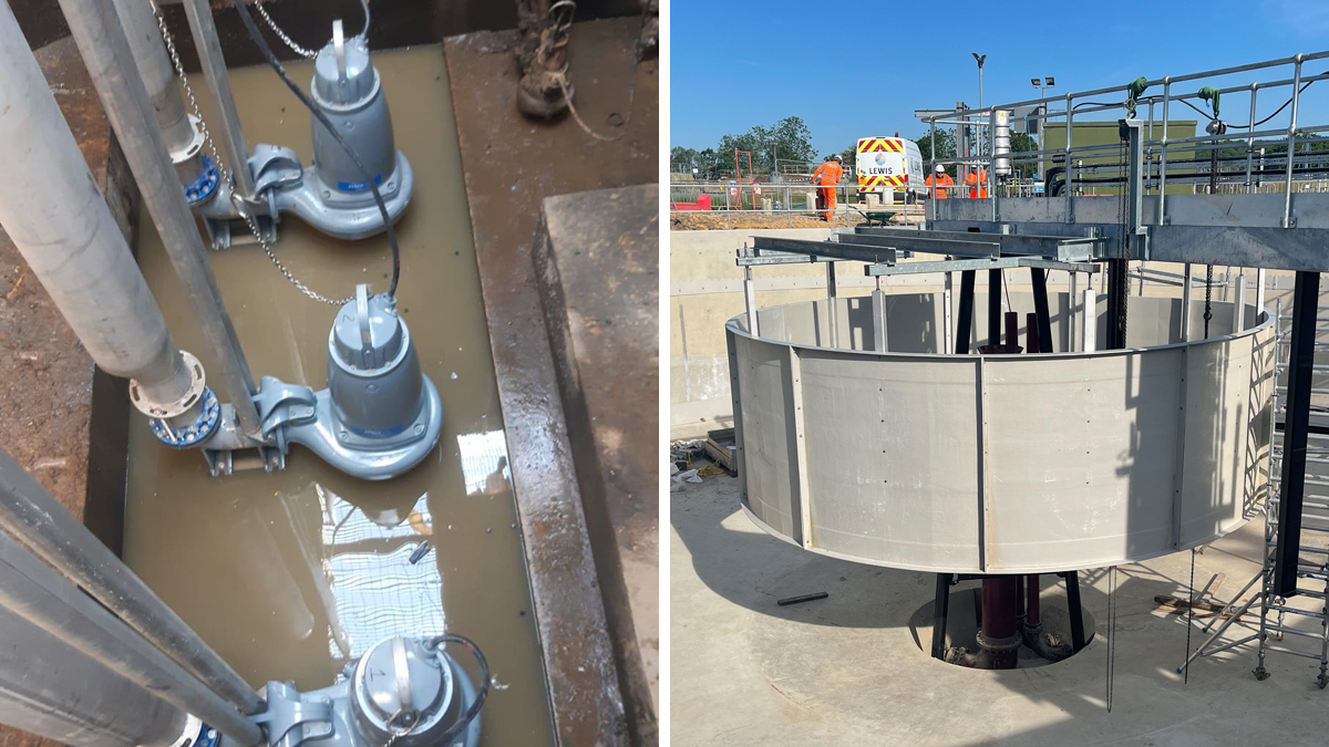
(left) Upgraded RAS pumping station and (right) FST4 diffuser drum installation – Courtesy of MWH Treatment
Bicester STW: Supply chain – key participants
- Principal designer & contractor: MWH Treatment
- Civil construction and pipelines: envolve infrastructure
- Mechanical installation: Alpha Plus Ltd
- Electrical installation: Lloyd Morris Electrical Ltd
- MCCs & systems integration: Total Automation & Power Ltd
- Metalwork: Steelway Fensecure
- Aeration system: Eliquo Hydrok Ltd
- Aeration blowers: Aerzen Machines
- Drum thickener: Alfa Laval Ltd
- Polymer dosing: Richard Alan Engineering Co Ltd
- Flow controls: AFFCO Flow Control (UK) Ltd
- FST scraper bridge: JK Fabrications Ltd
- Permanent lifting equipment: T Allen Engineering Ltd
- Kiosks: Kingsley Plastics
- Trace heating & lagging: Jade Insulation Ltd
- Technical documentation: 3rd Light Media
Engineering challenges
Activated Sludge plant (ASP): Prior to the scheme the site comprised 3 (No.) ASP lanes, configured to operate in parallel, with a common inlet and outlet chamber. The brief required the construction of a fourth lane to be seamlessly connected into the existing process.
During the ASP construction, the major challenges were the physical space for construction of the structure and its hydraulic connection to the existing ASPs.
The original construction had anticipated that at some point a fourth ASP lane would be added by incorporating a blanked off stub extension. Once the new lane had been constructed the original blanking plates could be removed. However, most of the provisions for expansion were deemed unsuitable, due to the extended period since construction. This legacy and other aspects of the design were included in a comprehensive efficiency challenge process.
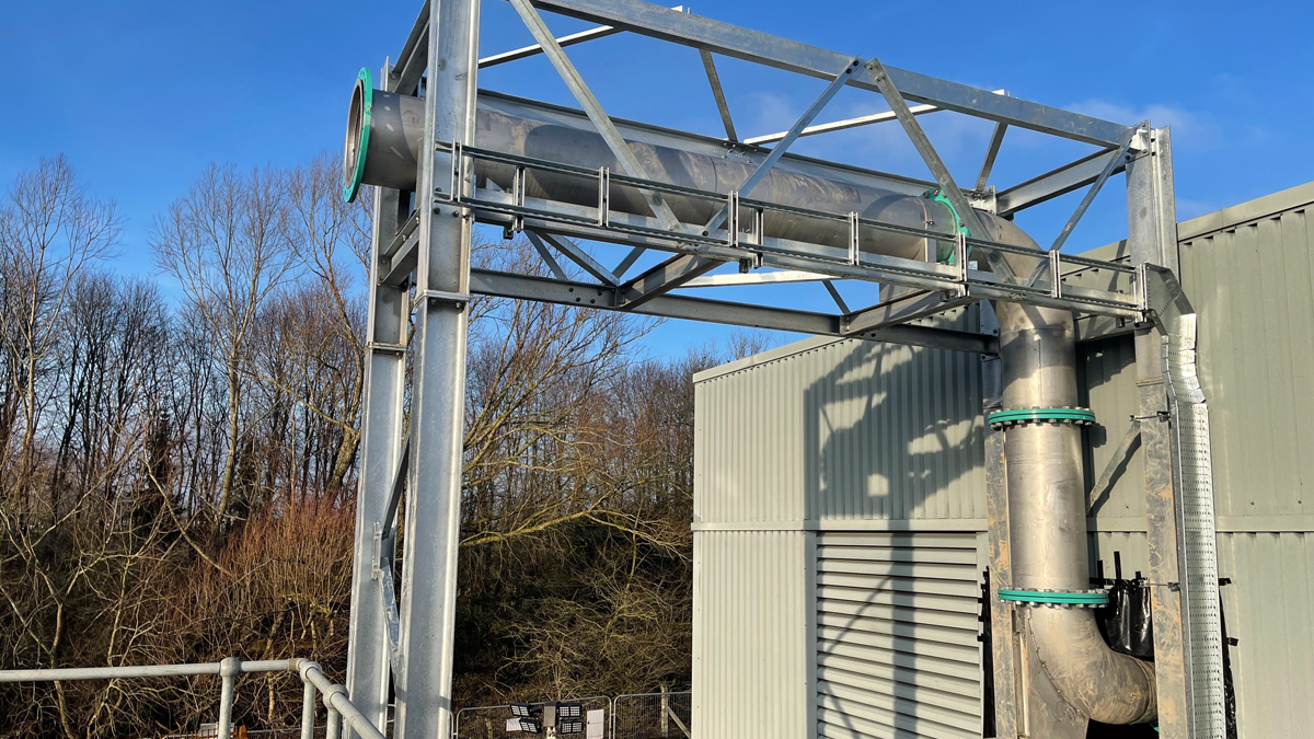
ASP air main during construction – Courtesy of MWH Treatment
Another key challenge was the positioning of the new 4th lane relative to ASP3 and the risk of differential settlement. The new structure was built independently with the only interconnections being the inlet and outlet channels, where flexibility was incorporated to accommodate differential movement.
A further engineering challenge resulted from the operational constraint that 2 of the ASP lanes were required to be kept in service at all times and the third could only be taken out of service for a period of up to 10 hours.
This was further complicated by the fact that the existing lanes were being retrofitted with the new aeration system. This required the new ASP lane to be completed and fully process commissioned before release of any of the existing lanes for retrofitting. Sequencing and logistics during installation were therefore key to ensuring the site always met its discharge consent during construction. Designing for construction and commissioning was included from the concept design to provide flexibility during the construction phase. An example of this was the location of the new motor control centre (MCC) to be installed to replace the existing.
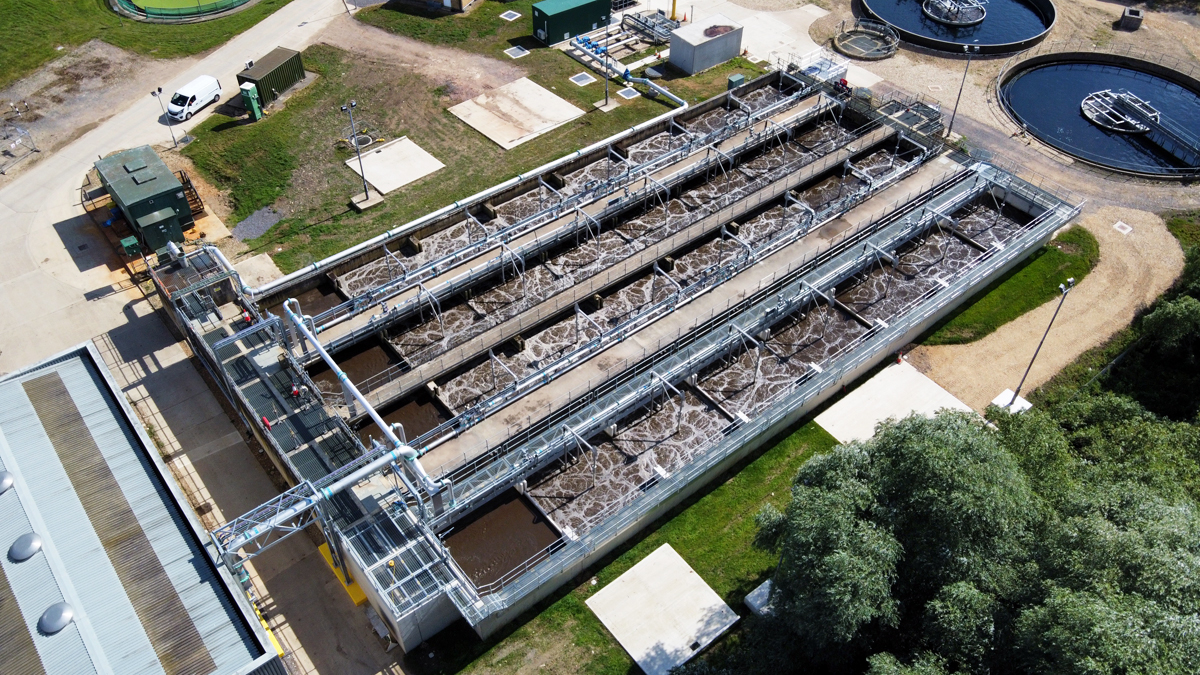
Completed new and furbished ASP lanes – Courtesy of MWH Treatment
A detailed assessment of the structural suitability of the existing mezzanine floor to support the existing and new MCCs during commissioning was required. The project team was able to install and commission the new blowers and the associated MCC without any process capacity reduction; maintaining ASP performance at all times. The constraints of having to maintain operation of the existing ASPs and reusing the existing building required a phased transition from existing to new control systems. This added to the logistical challenge of maintaining the effluent consent. The phasing required detailed liaison with the site’s operational team who were critical to successful project delivery.
MWH Treatment coordinated the design of four key members of the supply-chain across all engineering disciplines: the civil structure, the mechanical plant, the electrical installation, and the systems integration. Further subcontractors contributed to the ancillary works, and all were coordinated through the use of BIM. MWHT’s supply-chain provided BIM models of their individual plant which was used to produce an overall federated model. The model was required to be built in a very specific sequence replicating the subsequent construction. The different disciplines were included in different model layers which minimised service clashes and allowed the build sequence to be digitally rehearsed to improve coordination of the supply-chain activities.
Final settlement tank (FST) No. 4: Prior to the project the ASP stream operated with three FSTs. From the arrangement, physical investigation, and review of records, it was determined that the site originally consisted of two FSTs with the third added to increase capacity at later date. With growth in the catchment an additional FST was now required.
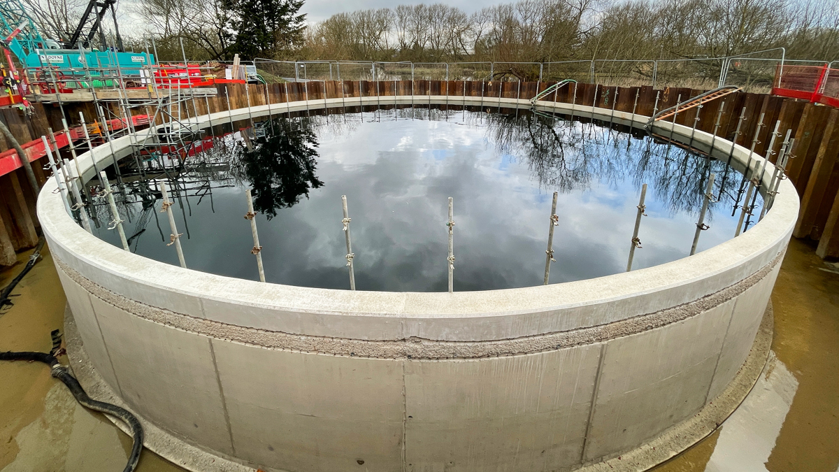
FST4 during water drop test – Courtesy of MWH Treatment
Final Settlement Tank 4 also had its engineering challenges. The primary issue being how to negate flotation of the structure itself. As part of the initial structural design, it was proposed that the sub-structure foundation was to be mass-filled with 4m to 5m of concrete down to bed-rock. This would have involved a significant amount of excavation down to the rock sub-strata before the mass concrete could be placed. This situation was exacerbated when the ground investigation determined that the underlying limestone was 1m deeper than anticipated. To overcome this, it was proposed that an alternative approach of installing piles would be a more cost and time effective foundation. Cost in that it would remove the need to bulk excavate down to the bed-rock, and time in that the overall foundation period would be significantly reduced. The change was carefully managed as part of a project delivery efficiency review and incorporated with no delay to the overall programme. The option also reduced the embedded carbon footprint of the project.
FST 4 Design challenges: Although the site was evidently designed to deal with future updates and upgrades, it was only designed to deal with a maximum of three final settlement tanks. The introduction of the fourth FST to cope with the additional flows created a challenge in how to uniformly distribute flows.
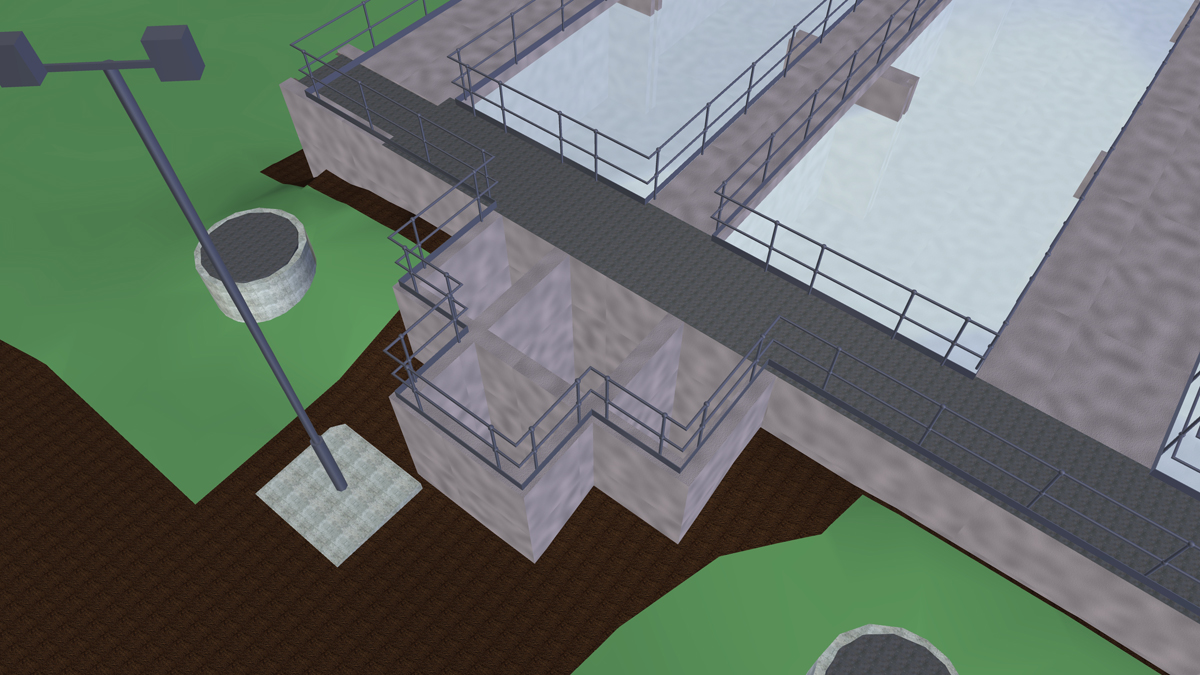
Extract from 3-D model showing ASP discharge flow distribution structure – Courtesy of MWH Treatment
Pre-scheme, the flow distribution chamber was designed to equally distribute flows from the three existing ASPs. To incorporate FST 4, the design remodelled this chamber so that there were three modified apertures; FST 1, FST 2 and FSTs 3&4 combined. To achieve this, the weir widths were adjusted so that FSTs 1 and 2 were 800mm wide and the combined weir to FSTs 3&4 was 1600mm wide.
The combined flow to FST3 3 and FST4 was then bifurcated at a new distribution chamber with the facility to allow fine tuning of flow distribution via two manually adjustable weir penstocks.
The biggest challenge for this remodelling was the logistics of construction and installation whilst maintaining the site fully operational; given the longest available outage was 10 hours. In order to coordinate these works a 4-D visualisation of the sequence of works was created. This was colour-coded to demonstrate the allocation of works between subcontractors. The visualisation is shown here:
Video: Bicester STW – FST 4 Flow Distribution
Additional sludge processing capacity: The required increase in sludge stream capacity in consequence of the effluent stream upgrade was addressed through the installation of an additional drum thickener to supplement the two existing units. The key engineering challenge was associated with upgrading the existing polymer dosing system in situ, followed by integration of the new drum thickener. Success was achieved by early involvement of the supply chain and additional collaborative planning workshops. Further improvements to the de-sludging system were made and with tanks removed from service in turn to facilitate construction; again requiring close liaison with the site’s operational team.
Covid-19
The project spanned the height of the Covid-19 pandemic. It is a testament to the collaborative working of the project’s delivery team that the potential time impacts were effectively mitigated. Uncertainty around Government restrictions on how projects were be managed did initially impact on progress. However, delay was recovered by resequencing work to limit numbers working in proximity and a monitoring programme was put in place to detect infection before workers arrived at site. Through these and other measures no single Covid-19 case impacted progress.
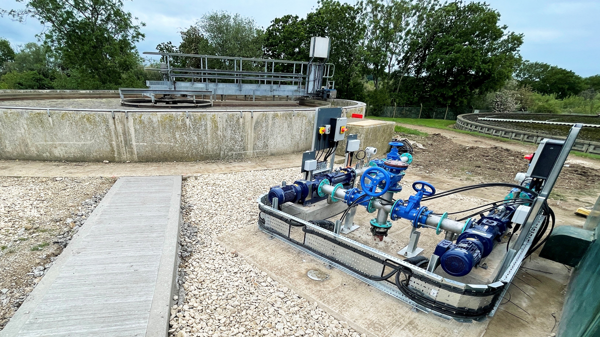
PST pump installation during M&E phase – Courtesy of MWH Treatment
Summary
Through an integrated approach including the client’s staff and the supply chain, the project team has delivered a significant upgrade to Bicester STW. The project was completed early in December 2021 and is now providing service to Thames Water’s customers and will continue to do so as the predicted population growth arrives. It is also worth noting that the project had an industry leading safety performance with no lost time injuries.


