Hampton Loade WTW (2023)
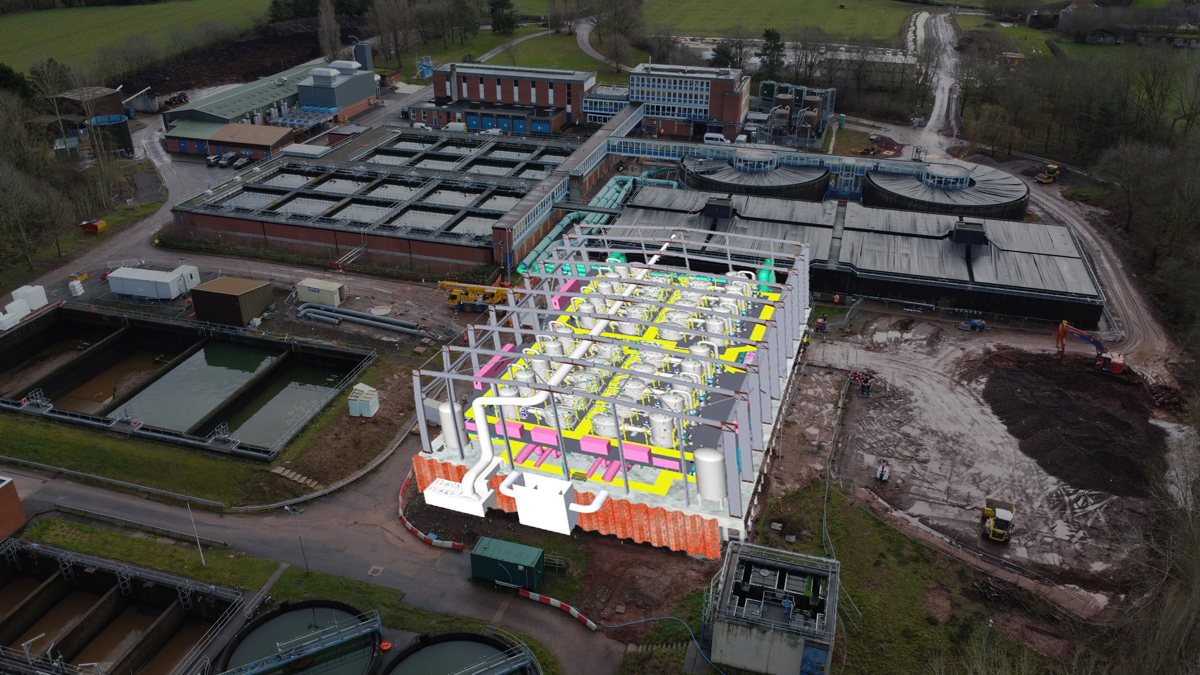
Hampton Loade WTW with 3D overlay of the ceramic filtration stage - Courtesy of Ross-shire Engineering
Hampton Loade WTW treats raw water from Chelmarsh Reservoir, located approximately two miles north-west of the site. The reservoir is supplied by the river intake pumps located within the intake building immediately adjacent to the River Severn. The maximum flow that can gravitate to the works from the reservoir is 130-135 megalitres/day (MLD). To increase the flow from the works up to the design value, there are four low-lift pumps which are also situated within the intake building. Following a Drinking Water Inspectorate (DWI) assessment of the works, South Staffordshire Water PLC (SSW) was issued notice LI/SST/2021/00001 that dictates the requirement for the completion of the construction, installation, and commissioning of a ceramic filtration stage by 31 March 2025. In addition to the second stage filtration, upgrades to the existing waste treatment system include a refurbished backwash process and sludge plant to be included in the AMP 7 works to address the expected waste levels.
Existing plant description
The raw water received from Chelmarsh Reservoir is received within the open-topped inlet tower, which acts as a hydraulic break. From the inlet tower the raw water flows to the two clarification streams via two large gravity mains, designated as red and green. Sulphuric acid is dosed within these mains between the inlet tower and the clarifier streams for pH correction.
After clarification, the clarified water is dosed with intermediate sodium hypochlorite (NaOCl), before gravitating to a filter stream. Each Accentifloc clarifier feeds four Phase 1 granular activated carbon (GAC) filters and each Superpulsator feeds five Phase 2 GAC filters. There are cross connections in the pipework between the clarifiers and the filters to allow any clarifier to feed any filter bank. The filters are segregated into phases such that Phase 1 consists of GAC Filters 1-8 and Phase 2 consists of GAC Filters 9-18. Originally designed as rapid gravity filters (RGFs), these GAC filters have been refitted with GAC media to act as a combined GAC contactor/filter process stage. This work was completed to address volatile organic compounds (VOCs) such as pesticide and algal contaminants in the raw water. The result of the redesign is less than optimal performance as a filter and a GAC contactor.
Following the GAC filters is the disinfection process. Each filter outlet is fitted with a medium pressure ultraviolet (UV) reactor to address clostridia and cryptosporidium. The outlets of all filters on each of the four banks then join into the four common outlet headers, each feeding one of the four contact tanks. Like the GAC filters, the contact tanks are separated into Phase 1 and Phase 2, with Tanks 1 & 2 treating water from GAC Filters 1-8 and Contact Tanks 3 & 4 treating water from GAC Filters 9-18. There are cross connections between tanks within each phase. Prior to entering the contact tanks, the filtered water is super chlorinated with NaOCl. The treated water from the contact tanks is then treated with fluoride, orthophosphate, sodium hydroxide and sodium bisulphite prior to entering the high-lift suction wells in the main site building. At the downstream end of Contact Tanks 1 & 2, there are three washwater storage tanks, each fitted with a clean backwash pump. These storage tanks are hydraulically linked to all contact tanks, although can be isolated via penstocks or valves.
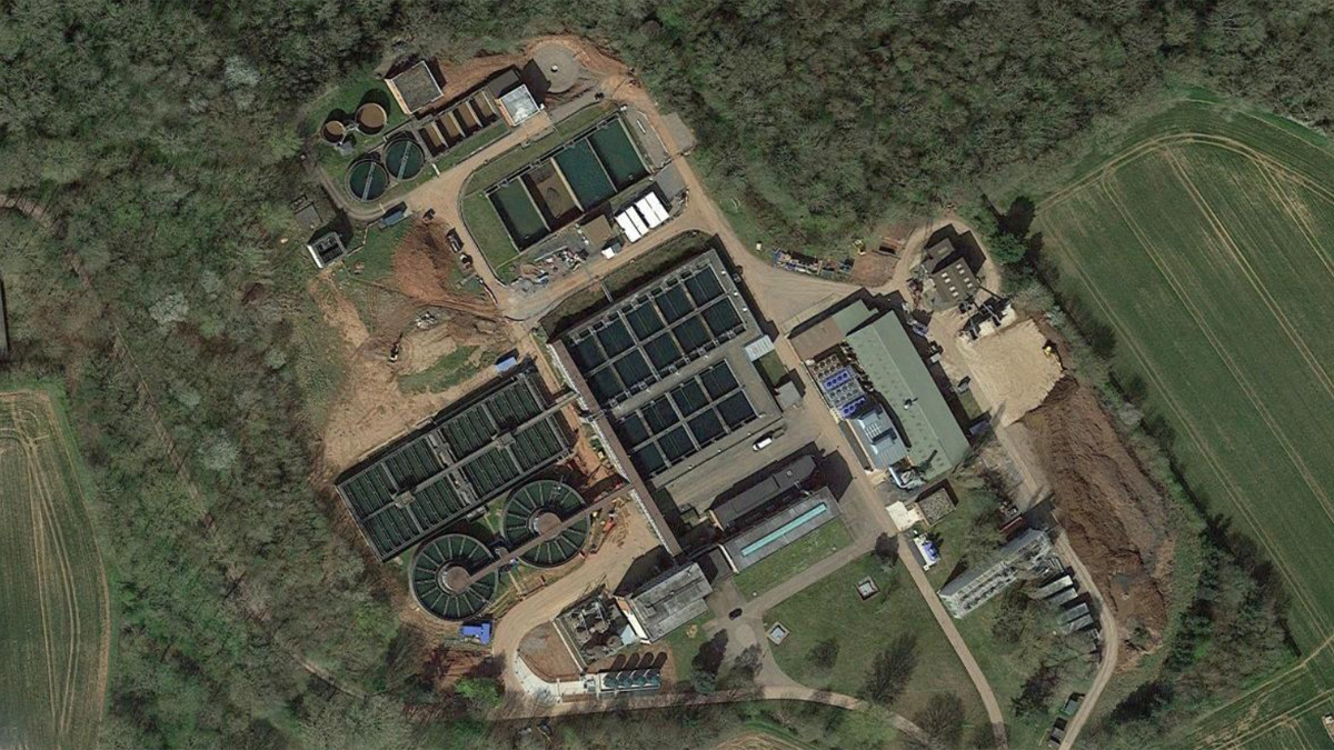
Google Maps image of Hampton Loade WTW – Courtesy of Ross-shire Engineering
Dirty washwater from the 18 filters is received in four dirty wash water storage tanks. These tanks are sequentially operated with one tank receiving flows, one tank settling washwater, one tank decanting settled washwater, and one tank desludging at any one time. Settled washwater is decanted via a floating arm fitted with an actuated valve. The decanted water then flows to the river via two discharge balance tanks. The resulting washwater sludge is pumped to two sludge balancing tanks via two desludge pumps. In addition to flows from the four dirty washwater storage tanks, the two balancing tanks also receive sludge from the two Accentifloc clarifiers and the two Superpulsators. The sludge from the sludge balancing tanks is then continuously fed to the two sludge thickeners. The sludge is dosed with polymer at the inlet to the thickeners. Supernatant from the thickeners flows to the two discharge balance tanks by gravity. Thickened sludge from the bottom of the thickeners is then pumped to the two hydraulically linked sludge holding tanks for storage. Thickened sludge is dewatered by two centrifuges, each fed by a dedicated feeder pump drawing from the sludge holding tanks. Sludge cake from the centrifuges is deposited into sludge skips outside of the centrifuge building by two screw conveyors. When the skips are full, the cake is transferred to land where it is stored on site before disposal to agricultural land near to the Chelmarsh Reservoir.
Defined solution
The defined additional stage of filtration at Hampton Loade WTW will consist of new CeraMac® vessels physically located between the inlet tower and the Superpulsators. The new CeraMac® plant is an interstage filtration system that will operate downstream of the existing clarification process and filtered water will be returned into the process upstream of the existing GAC filters.
The CeraMac® solution was chosen as it provides an advantage over RGFs due to the robust physical barrier it presents against particulates. Due to the 0.1-micron pore size within the membrane, the CeraMac® process provides an absolute barrier against cryptosporidium oocysts and the clostridium perfringens bacteria that is present within the raw water at Hampton Loade WTW. This presents the opportunity to use the process as a disinfection stage in the disinfection policy, over the existing UV process which is associated with considerable operational and energy savings, which successfully attracted green recovery funding. In addition to the cost benefits, the CeraMac® process produces effluent of a higher quality, and is less dependent on the influent turbidity, than the RGFs. This results in a process that is able to reliably produce high quality filtrate and is resilient against variable water quality.
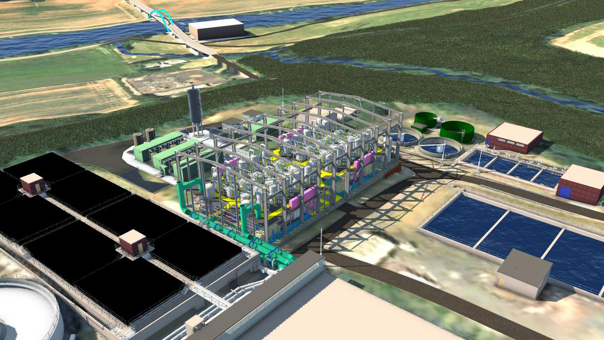
3D render of Hampton Loade WTW CeraMac® filtration stage – Courtesy of Ross-shire Engineering
Hampton Loade WTW: Supply chain – key participants
- Principal designer & contractor: Ross-shire Engineering Ltd (RSE)
- CeraMac® membranes/process input: PWNT
- Structural & civil design: Wallace Stone LLP
- Supporting steelwork & pipework: RSE
- HV studies: Couch Perry & Wilkes LLP
- ICA & MCC design: Blackburn Starling Ltd
- Groundwork & civil construction: Barhale
- Sheet & CFA piling: Aarsleff Ground Engineering
- Formwork & rebar: Jones Reinforcements Ltd
- Main building: Structural Steelwork Ltd
- Compressors: Atlas Copco
- Sulzer Process pumps: Sulzer Pumps Wastewater Ltd
- Air spring vessels: CPE Pressure Vessels Ltd
- Pipework: Cleveland Steel & Tubes
- Pipework: DH Stainless
- Large diameter flanges: JR Whitehead Flanges & Valves
- Valves & pneumatic actuators: Socla UK
- Flow controls: AFFCO Flow Control (UK) Ltd
- Pneumatic control banks: Burkert Fluid Control Systems
- Chemical dosing: RSE
- Chemical dosing pumps: Prominent Fluid Controls
- Chemical tank bund gratings: Relinea
- Chemical dosing pipework: Georg Fischer
- LDPE Protectaflex chemical dosing lines: FT Water Treatment
- Chemical dosing kiosks: Pro-tect GRP Enclosures Ltd
- Chemical dosing tanks: Forbes Technologies
- PAC storage silos: Spirotech Group Ltd
- Safety showers & eyebaths: Aqua Safety Showers International Ltd
- Permanent cranes: Street Crane Co Ltd
- MCC & switchboards: Blackburn Starling Ltd
- Electrical installation: MCD Electrical
- HV switches: Schneider Electric
- HV/LV transformers: Bowers Electricals Ltd
- Level transducers & flow meters: Siemens
- Instruments (pH & ORP): Endress+Hauser
- Instruments (turbidity): Hach Ltd
- Instruments (pressure): IFM Electronic
- Instruments (pressure): Trafag Sensors & Controls
- HVAC: Air Technology Systems Ltd
- Specialist transport: GF Job
CeraMac® filtration
The project will deliver 20 CeraMac® vessels split into two banks of ten as process streams. Each process of the streams will be complete with backwash and air spring systems. Each C90 vessel unit will comprise of 90 filter units, totalling 1800 filter elements for the whole scheme. RSE’s ability to bring off-site construction techniques into the challenging programme will help meet the required DWI deadline.
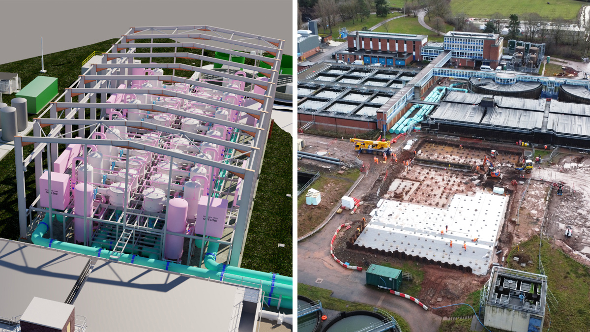
(left) Render of the Hampton Loade WTW CeraMac® plant and (right) construction progress to date (February 2023) – Courtesy of Ross-shire Engineering
Dedicated feed pumps for each of the CeraMac® units will be located within the basement of each CeraMac® building. These will pump forward water from the existing clarifier units onto the CeraMac® membranes, delivering back to existing GAC filters and situated at a level to ensure safe and reliable operation.
An extensive cleaning and neutralisation process is included to ensure that the membranes can be kept clean and allow for maximum production requirements. This involves the provision of new storage and processing equipment.
Controls & electrical
Fully online instrumentation and condition monitoring systems are being put in place with motor control centres (MCCs) and latest programmable logic controller (PLC) networking technology to keep a watchful eye over the plant and provide information back to the supervisory control and data acquisition (SCADA) system in the central control room.
The existing high voltage (HV) system is being extended to include two new feeds to dedicated transformers feeding a new low voltage (LV) board system.
The scheme has been designed so that there are no single points of failure, ensuring a reliable and robust treatment process.
Civils works
The civil works comprises significant groundworks and a new building complete with chemical storage and dosing areas, with an extension to existing and new access roads and pedestrian footpaths to facilitate adequate maintenance access and egress.
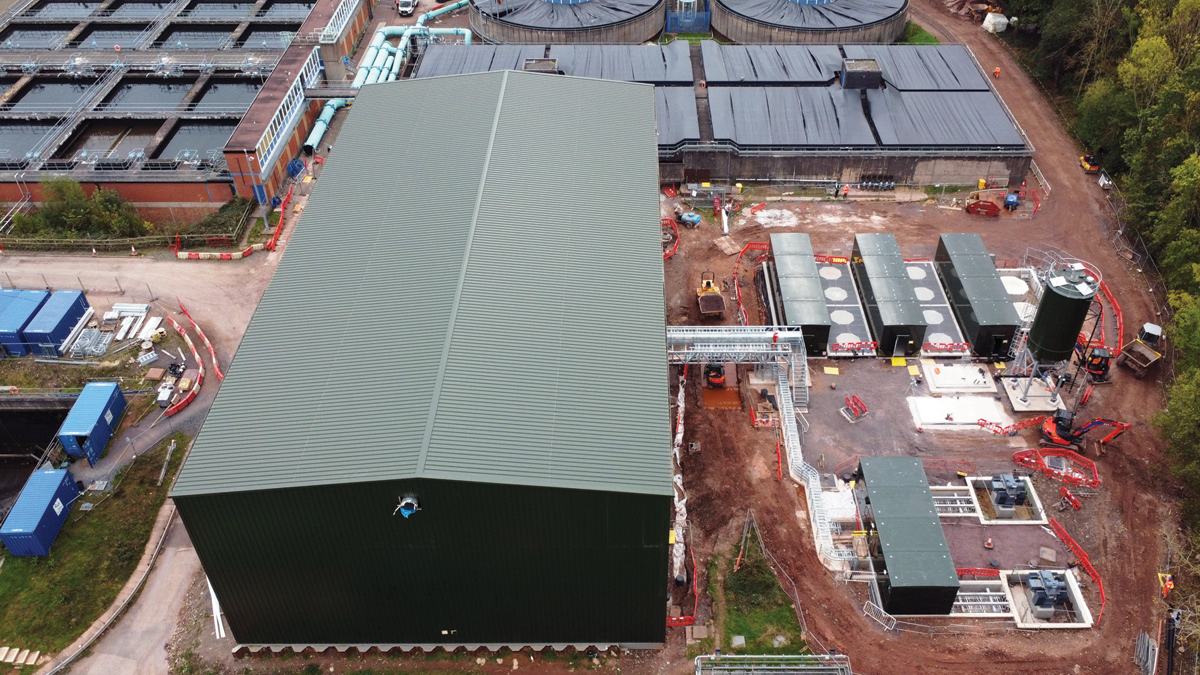
Progress at Hampton Loade CeraMac® membrane plant (October 2023) – Courtesy of Ross-shire Engineering
Progress & project timings
The refurbishment project at Hampton Loade WTW is part of South Staffs Water’s current investment upgrade programme, designed to develop existing water treatment sites to continually improve water quality for customers across the region. The construction, installation, and commissioning of a ceramic filtration stage is due to be completed by the end of March 2025.


