Invercannie WTW (2020)
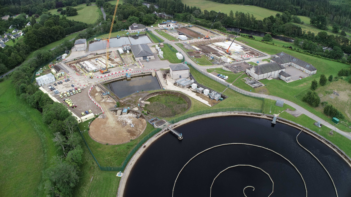
Invercannie WTW - Courtesy of ESD
Located to the West of the town of Banchory, Aberdeenshire, Scottish Water’s Invercannie WTW is currently a 49 Ml/d water treatment works which serves the local population as well as providing raw and treated water to Mannofield WTW in Aberdeen via two 28km aqueducts (one laid in 1866 and the other in 1924). The treatment plant, which was originally built in 1866 to supply water to the city of Aberdeen, draws its water from the River Dee and serves around 300,000 customers across the North East. Her Majesty Queen Victoria officially opened the Invercannie WTW on 16 October 1866.
Existing works
The current works consists of a raw water pumping station feeding two raw water reservoirs from which the raw water is passed to an inlet works consisting of screening, pH correction (lime) and coagulation (PACL). The coagulated water is then filtered at an ultrafiltration membrane plant and the filtered water is pumped to a chlorine contact tank for disinfection (sodium hypochlorite), pH correction (lime) and chloramination, before passing to the 1924 aqueduct from where it gravitates to the supply zones, including Aberdeen. A treated water pumping station draws from the aqueduct within the WTW boundary and serves the Glendye supply zone. A further treated water pumping station is located 2km from the site boundary and draws from the aqueduct to serve the Laird’s Cast supply zone. The membrane backwash water is treated by lamella clarifiers, WRc picket fence thickeners and a sludge press.
The current treatment process of ultrafiltration membranes was installed around 2008 and prior to this, the site consisted of a number of slow sand filters. The redundant slow sand filters will be utilised to provide the area to construct the new assets required under this project.
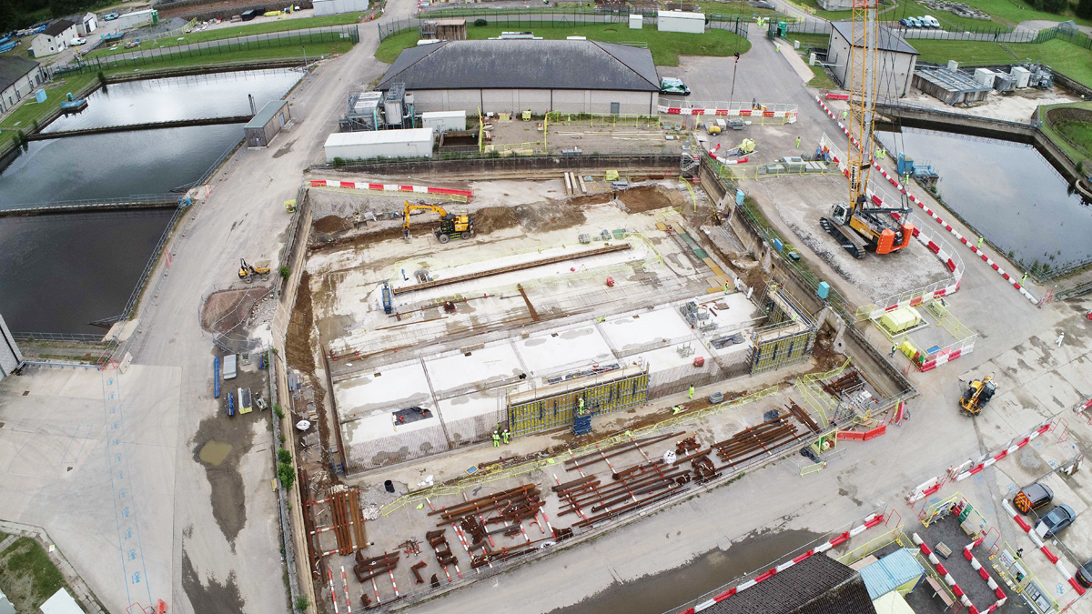
DAF plant construction within redundant slow sand filters – Courtesy of ESD
Project objectives and scope
This project drivers are:
- Reduce turbidity and colour loading on the membranes and reduce the risk from cryptosporidium.
- Upgrade the works to treat an inlet flow of 70 Ml/day on a consistent basis.
- Reduce the risk of loss of water supply from plant shutdown, spate events or acute pollution events by provision of treated water storage at the works.
The project will add a clarification stage upstream of the ultrafiltration membrane plant by way of a DAF plant and also provide a new chlorine contact tank and 19 Ml clear water tank downstream of the membrane plant for improved disinfection control and treated water storage. Ancillary equipment will be provided to supplement the new DAF and CWT with sulphuric acid and caustic dosing for raw water pH control, replacement membrane filtrate pumps, sodium hypochlorite dosing plant for disinfection, new lime plant for final water pH correction, poly dosing for sludge thickening, one additional WRc picket fence thickener, sludge supernatant treatment plant (continuous sand filter) and service water system. A replacement for the Lairds Cast Treated Water Pumping Station will also be constructed within the site boundary at Invercannie and draw from the CWT outlet reducing the flow to the aqueduct.
The project is being delivered by ESD; a Binnies, MWH Treatment and Galliford Try Joint Venture formed in order to manage, design and deliver Scottish Water’s Q&SIV Non-Infrastructure Programme.
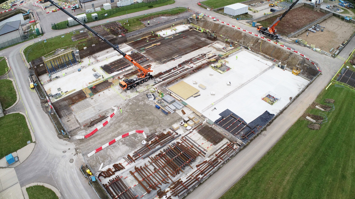
CWT construction underway within redundant slow sand filters – Courtesy of ESD
Collaborative project approach at outline design and scope definition
During the outline scope definition and design phase of the project a collaborative project approach adopted with the project team consisting of members from both ESD and Scottish Water. The collaborative project delivery model allowed for a scope definition phase to feed straight into the Design Phase. The design was progressed to a detailed design phase on the major project areas and at this point design would carry on to detailed design across the full project whilst the enabling works and estimating were run in parallel.
The project team embraced the principles of Agile Project Management including accommodating change, working face to face/co-location, reflection and adjustment. This meant that efficiencies can be realised early in the project lifecycle with decisions made by involving all relevant client and contractor stakeholders. The collaborative delivery model has enabled design issues to be identified and addressed at an earlier stage. This has generated project savings in time and cost as these issues traditionally would not be identified and addressed until technical review/governance stage causing disruption to the project.
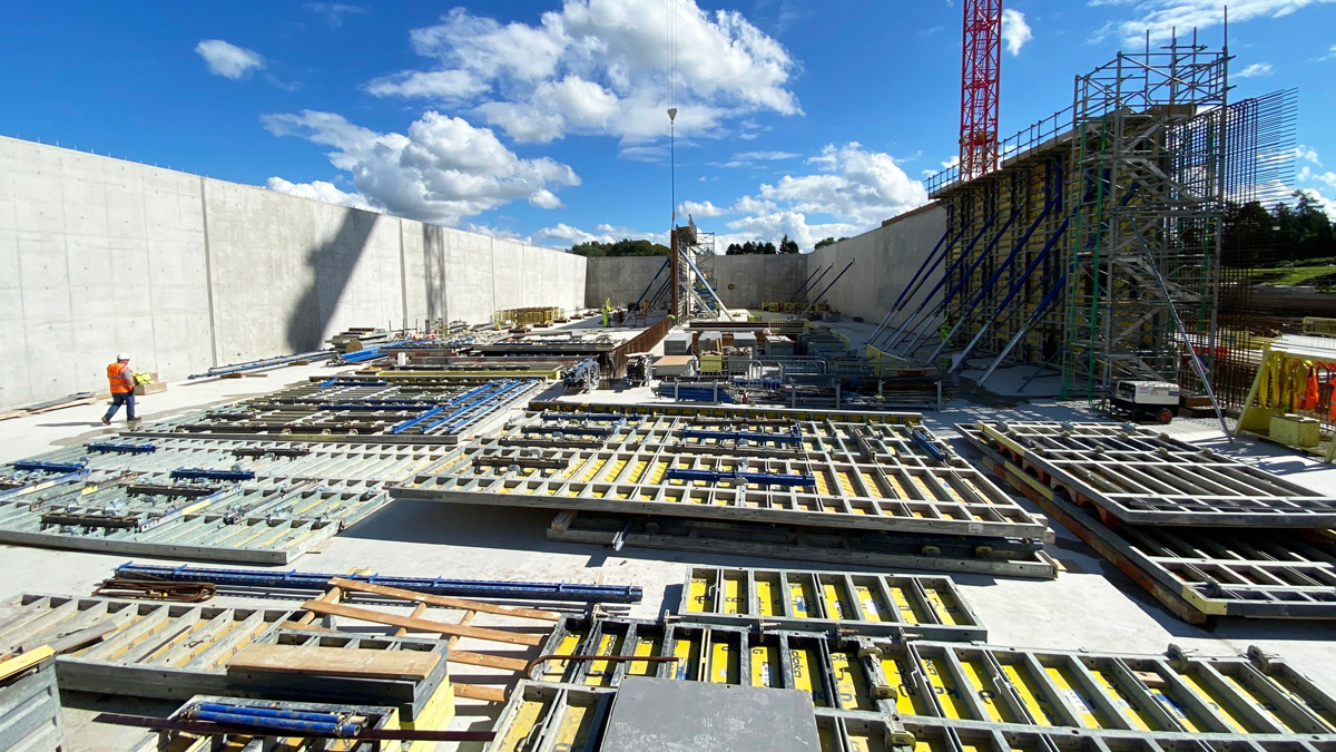
Construction of the CWT internal walls and columns – Courtesy of ESD
PACL
The original scope for the PACL dosing was to install a new PACL dosing plant with day tanks and new dedicated dosing pumps local to the new raw water point of application. The existing PACL bulk tanks would be retained and new transfer pumps installed to feed the day tanks. However, from review with Scottish Water it was identified that this new arrangement would not address the current operation issues at the PACL plant which regularly blocks and is required to be taken offline and manually flushed with hot water. Therefore, the project team proposed an alternative solution to include for a hot water tank and automatic flushing system to avoid the blockages seen at the existing PACL plant. The existing dosing system pumps could then be retained, and new dosing lines run to the new point of application.
Optimisation of major structure sizing
During the outline design phase there was the opportunity to carry out a review of the sizing of the major structures to be constructed in this project (DAF plant, CCT and CWT). This was carried out by the ESD project team, alongside Scottish Water Operations, Capital Liaison and Technical Support & Assurance, with the view to optimise the solution whilst giving the operational robustness and flexibility required. This resulted in a change to the hydraulic profile through the CCT and CWT, which resulted in a reduction in overall wall height of the CWT by 3m and the removal of a chlorinated overflow from the CWT. The pre-CCT pipe gallery to CCT to post-CCT pipe gallery to CWT cells was designed to be hydraulically linked to allow any potential overflow to backup and overflow upstream of the sodium hypochlorite dosing. This reduced the overall height of the tank, which resulted in CAPEX and OPEX savings, whilst also presenting a solution with a lower environmental risk. During this collaborative review, the CCT volume was also able to be significantly reduced from 1600m3 each to 700m3 each whilst meeting the requirements of the Scottish Water disinfection requirements. This was achieved by optimising the inlet arrangement and flow distribution through an inverted inlet pipe and inclusion for flow baffles as determined by CFD modelling.
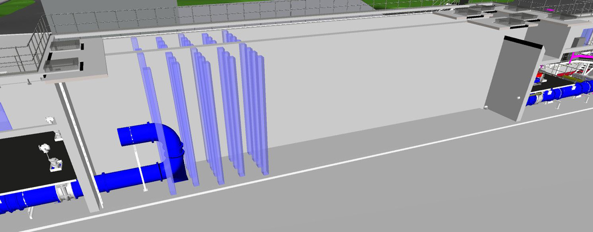
3D model of the CCT shown on BIM360 Glue – Courtesy of ESD
DAF plant arrangement
The DAF plant sizing and arrangement was also reviewed and challenged with significant changes implemented early in the design phase with agreement between ESD and Scottish Water. The number of DAF streams was reduced from six to five, whilst still maintaining the treatment capacity and redundancy required. The benefit of this is seeing is reduced MEICA costs and OPEX saving in reduction in MEICA assets to maintain. An alternative inlet arrangement to the DAF plant was also proposed by the design team at this stage to allow for an inlet manifold with individual isolation valves, flowmeter and flow control valves to each DAF stream as opposed to an open channel arrangement. The benefit of this arrangement is seen in the operational flexibility of the DAF plant, where the DAF plant will be able to react to downstream step changes in flow, will have the ability to ramp down to minimum flow easier, and will achieve a better flow control/balance to each stream. The manifold arrangement also removes the requirement for an overflow immediately upstream of the DAF plant which would be coagulated water. With the manifold arrangement, a clarified water overflow is provided downstream of the DAF, but upstream the flow would be allowed to back up to the raw water storage reservoirs and the river water intake pumps can be stopped. Environmental impact is reduced here as well as the construction saving in the requirement for overflow pipe, which would need to have the capacity to discharge 70 Ml/d to the outfall.
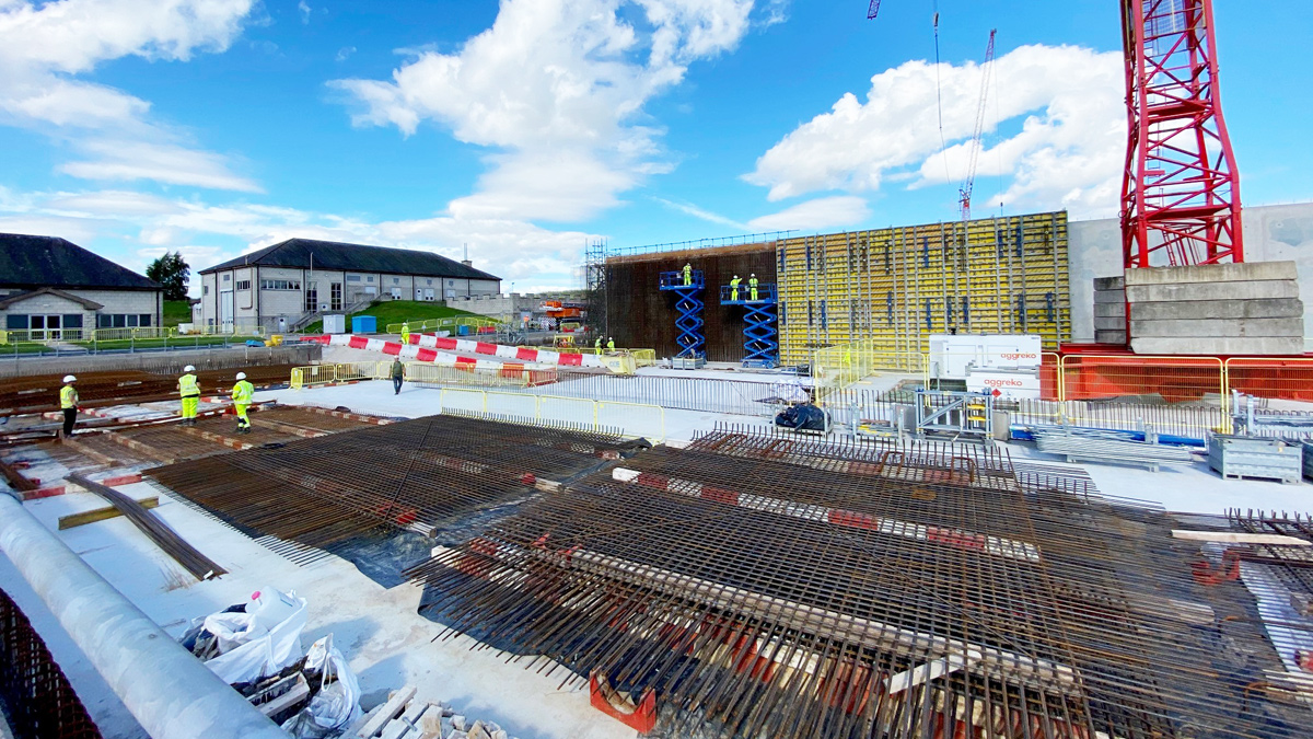
Steel fixing area within CWT footprint and construction of CWT internal walls – Courtesy of ESD
Inlet screen removal
The conceptual design included for 2mm inlet band screens and screenings handling equipment on the raw water line upstream of the DAF plant. The inclusion of these screens was to mirror the existing treatment process, but with the addition of the DAF clarification stage, these screens were deemed to be not required. The decision taken to remove the screens was taken as a project team with each of the individual stakeholders’ concerns addressed. Removing the screens gives an obvious CAPEX and OPEX reduction, but also has the added benefit of reducing the hydraulic losses from the raw water reservoir to the DAF plant, thus increasing the useable volume within the raw water storage and increasing the works ability to deal with raw water quality issues such as river spate.
Enabling works
A further benefit seen from the collaborative delivery model was identifying and focusing the detailed design for the major and designing the required enabling works ahead of other areas. The DAF plant and CCT/CWT are to be constructed in the footprint of redundant slow sand filters. This allowed the on-site enabling works to be carried out concurrently with the design, saving four months on the construction programme. The enabling works included the removal of sand media from the redundant slow sand filters, demolition of the internal walls, excavation to the new pipe gallery foundation level, blinding to tank base level and removal of redundant cabling and electrical equipment. The sand removed from the filters was stockpiled for re-use as pipe bedding material, the rebar from the demolished walls was separated for recycling, and the concrete from the demolished walls was crushed on site to be re-used as structural fill and blinding material.
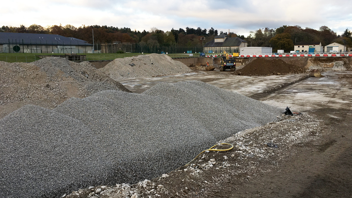
Enabling works within redundant slow sand filters – Courtesy of ESD
Left shift/early supply chain engagement
Early engagement of the supply chain was undertaken to allow supplier design to be integrated into the project. Installation subcontractors were also engaged, and collaborative meetings held with the project team to gain an early input to buildability.
Invercannie WTW: Supply chain – key participants
- Client: Scottish Water
- Principal designer and contractor: ESD JV
- Enabling works and demolition: Joseph Gallagher
- Concrete supplier: Breedons
- Formwork, rebar and concrete contractor: Careys
- Chemical dosing: Ross-shire Engineering
- Safety showers & eyebaths: Aqua Safety Showers International Ltd
- Electrical installation contractor: ICS
- Mechanical installation contractor: Dustacco
- UV Systems: Trojan Technologies
- Sludge transfer progressive cavity pumps (Invercannie): SEEPEX UK Ltd
- Steel tanks: Goodwin Tanks
- Static mixers: Statiflo
- Access steelworks: AJ Engineering & Construction Services Ltd
- Security covers: Technocover
- Access chambers: Cubis Systems
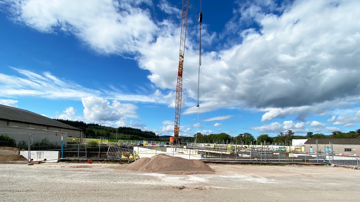
Crawler crane for construction of the new DAF plant within redundant slow sand filters – Courtesy of ESD
Use of digital design and delivery tools
The project has utilised a digital delivery model utilising digital tools from Initialisation to engineering to construction and commissioning. 3D laser scanning was undertaken at the start of the project to create a Recap model and 3D point cloud to produce the baseline 3D model. The Recap model allows ‘access’ to the external and internal layout of the site from a remote login and gives an initial visualisation of the site for contractors and supply chain through a 3D fly-through video.
The design was then progressed using 3D modelling, with civil and mechanical CAD technicians working with engineers and created an overall federated model. Supply chain 3D model blocks were also integrated at this stage. The 3D model was shared with Scottish Water engineers, operators and project managers using BIM360 Glue to allow real-time sharing of the development of the design and allowing feedback, mark-ups and comments to be returned to the design team. The sharing of the model in this way ensured that the formal reviews (HAZOP and ALM) were undertaken with a previous knowledge of the layout and plant.
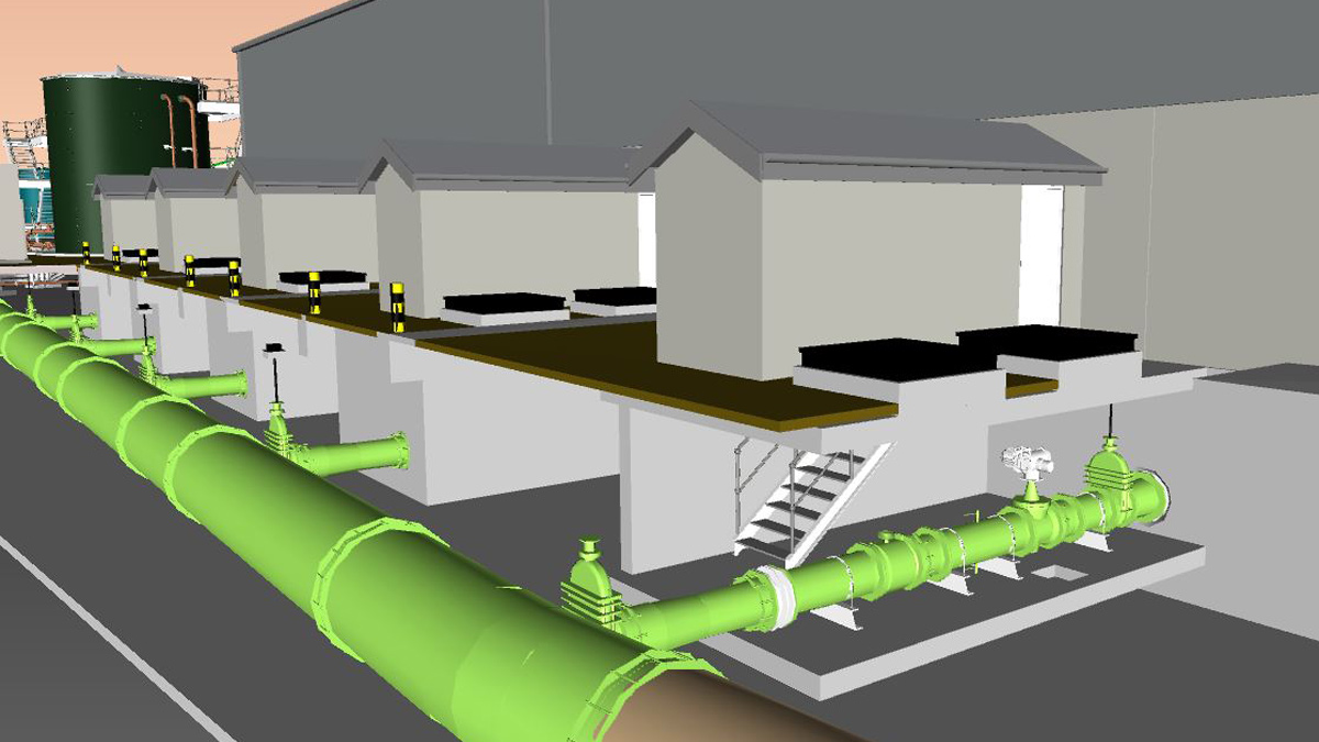
3D model of the DAF plant inlet manifold shown on BIM360 Glue – Courtesy of ESD
The 3D model was further developed and integrated with the site construction programme to create a 4D Synchro output to be able to visualise the construction phases of the project, allowing for clashes to be identified and the programme and procurement to be phased, allowing for work at multiple areas on site with the DAF and CWT structures being constructed concurrently. The use of 4D Synchro was key in the design of the raw water tie-in at the east reservoir. The original design included for a new 4-way valve chamber to be installed between an existing valve chamber and the reservoir. This design was optimised using 3D modelling and 4D Synchro to show the existing valve chamber could be re-used and re-purposed to create the new pipework arrangement required. Initial sketches were prepared to show the multiple chronological phases of this work showing temporary pipework, isolations and bypass, which were then developed into a 4D Synchro model. This was able to clearly articulate to Scottish Water Operations what the arrangement would be at each stage of the construction of this element of work, whilst minimising the risk to supply by reducing the excavation close to the existing raw water reservoir.
The use of digital tools continued into construction and commissioning, with the use of BIM360 Field for site reports, snagging and inspection and test forms. HoloLens technology is also being utilised for remote site tours, meaning that snags can be reviewed immediately without the need for travel to site, which has been particularly important to limit the number of persons on site during the COVID-19 restrictions to protect the Scottish Water workforce.
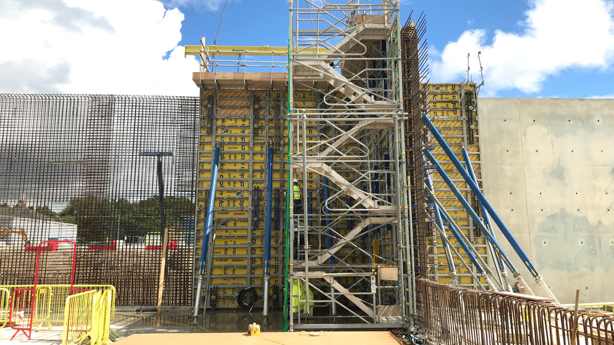
Construction of the 8m tall CWT external walls – Courtesy of ESD
Site progress
Following completion of the site enabling works and detailed design of the CWT/CCT and DAF substructures, the start of the permanent works commenced in March 2020. The works were stood-down following one week on site due to COVID-19 and restarted in June 2020.
Works have progressed extremely well since restarting with over 5,000m3 of concrete poured in just 10 weeks; 73% of the substructures. The start of the mechanical installation works commenced in August 2020, ahead of programme. This has been achieved as a result of collaborative working, with both the client and the supply chain specialists.
Conclusion
This collaborative project approach has been well received within Scottish Water who have replicated this on other projects in SR15 (e.g. Craighead WTW) and looking to embed this approach into the future SR21 framework, with early projects at Herricks WTW and Glenfarg WTW, utilising an integrated approach between ESD and Scottish Water for scope definition, option selection, outline design and estimation.


