
Knostrop Sludge Treatment Facility (2018)
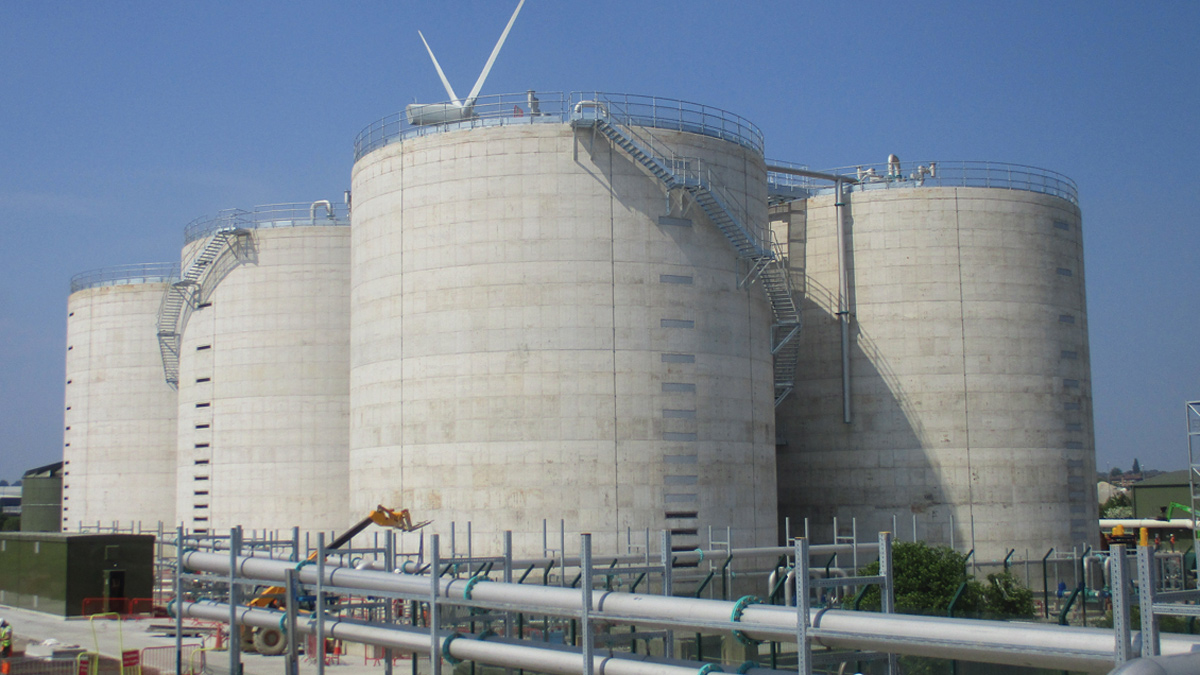
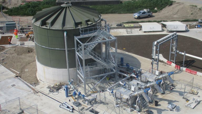
General view of digester compound under construction - Courtesy of YWS
The Yorkshire Water sewage sludge incinerator at Knostrop WwTW is approaching the end of its asset life in AMP7. This, along with high operating costs has driven a business need to review the long-term treatment of sludges in the Yorkshire/Leeds catchment. Following a strategy review, Yorkshire Water Services (YWS) decided to progress with conventional mesophilic anaerobic digestion (MAD) plant supported by lime sanitisation of the digested product to secure the long-term treatment of sludge for the area. The change in treatment direction brings the benefit of renewable generation from biogas production and increased reliability and performance. The total cost for the project is £73m.
Project scope
Black & Veatch Ltd (B&V) has been selected by YWS to design, construct and commission the new Knostrop Sludge Treatment Facility in Leeds. The anaerobic digestion plant will treat all the indigenous sludge (primary & SAS) from Knostrop WwTW. In addition, as the site will be a regional sludge treatment facility and will receive imported sludge in both liquid and dewatered cake forms. The digested sludge will then be lime sanitised to pH9 and dewatered on site before being recycled as a soil conditioner.
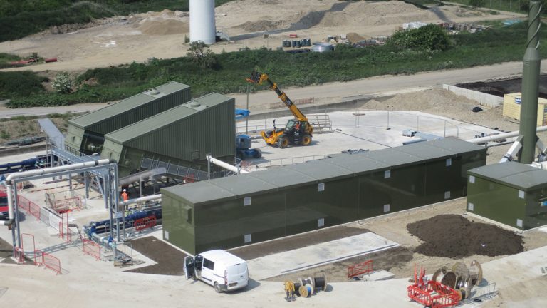
Sludge cake reception plant under construction – Courtesy of YWS
The scope of the project is to provide:
- Imported sludge tanker points for cake and liquid sludge: The imported sludge passes to a storage tank where it mixes with the indigenous primary sludges before screening.
- Primary and imported sludge screening: Sludge gravitates from the imported/primary sludge tank through the screens and it is then pumped to the storage tanks upstream of the sludge thickening facility.
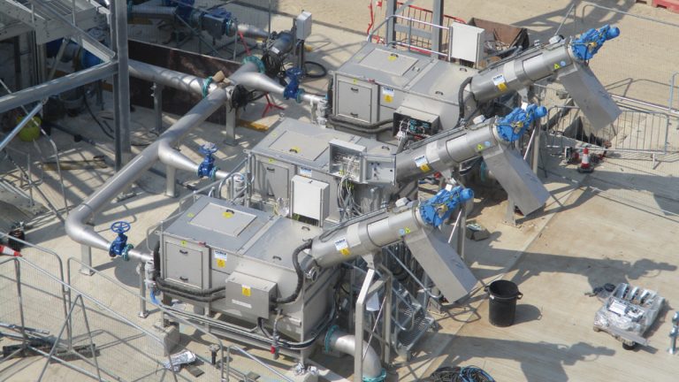
- Combined primary sludge and SAS thickening: Sludge will have polyelectrolyte added and will be thickened to around 6% using 5 (No.) drum thickeners (duty/duty/duty/duty/standby).
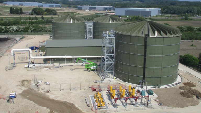
Sludge thickening process area under construction – Courtesy of YWS
- Digester feeding system: Thickened sludge passes to a digester feed tank from where it is pumped to the digesters.
- Digesters: 4 (No.) each 7,306m3 capacity.
- Gas holder and handling system: This comprises pipework from the digesters to the new gas holder and from the gas holder to the CHP/boilers. A flare stack will also be provided where excess gas is burnt off that cannot be used within the process.
- 2 (No.) CHPs: These will be the primary users of the biogas from the process. The CHPs will generate electricity to reduce the site reliance on imported power and the waste heat from the CHP will be used to heat the digesters. This will include provision of HV equipment to pass the energy generated from the CHP forward to the external grid.
- 2 (No.) dual fuel boilers: These will operate either on failure of the CHP or to provide supplementary heat when the CHP are operating but cannot provide the full heat requirement. The boilers will run on biogas as their primary fuel with natural gas as the secondary fuel.
- Sludge heat exchangers: The heat exchangers will take the heat from the CHP/boilers and transfer it into the sludge contained within the digesters. This will ensure that the digesters are operated in the temperature range 36-39°C.
- 3 (No.) dewatering centrifuges: The centrifuges will dewater the digested sludge to around 25% prior to loading directly onto HGVs for export.
- Liquor treatment plant: The STF will have a purpose-built liquor treatment plant (LTP) which is based on the DEMONTM process (supplied by SWECO). The ammonia levels from the LTP will be reduced by 85% prior to returning to the main WwTW such that the liquors do not have a detrimental impact on the existing activated sludge process of the main high level WwTW.
- Odour control: The odour control is for all tanks that are covered in the digestion area and also for the sludge thickening plant.
- Welfare and laboratory facilities: B&V will also provide a new control building, welfare and lab facilities for the site.
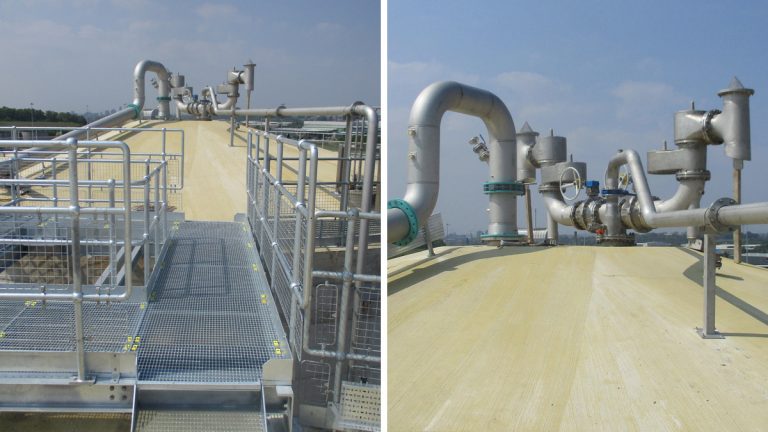
Digester roof during construction – Courtesy of YWS
Potential future expansion
It is likely that the works will be upgraded in the future to provide either a thermal hydrolysis plant or a further expansion to the existing mesophilic anaerobic digestion (MAD) plant.
This phase of the works has been designed to allow future expansion of the site to accommodate these options.
The digestion site in numbers
The CHP and digesters will be the largest units installed within the YWS region.
- The sludge load to the digesters is 30,000tds/annum (average daily) 48,000tds/annum (maximum) including up to a maximum of 10,284tds/annum of imported liquid sludge and 17,815tds/annum sludge cake respectively.
- The CHP will generate 23.4GW/year of electricity (enough to power 5100 houses).
- The volume of each digester is 7,306m3.
- The total gas production (average) from the digesters will be 27,740Nm3/d.
- The capacity of the gas holder will be 3,699m3.
- Total heat input (average) into the digesters will be 2536KW.
- The CHP will generate around 50% of the site’s power needs.
Liquid sludge reception plant under construction – Courtesy of YWS
Technical excellence/innovation
The design has used the limited space available efficiently to allow for future expansion. The efficient design also has to ensure that the operation and maintenance of the new equipment is not compromised. B&V has been able to rationalise the site layout to give:
- A single area for unloading of thickened and thin imported sludges.
- A common area for unloading of liquid chemical deliveries of polyelectrolyte, anti-foam chemicals and ferric.
- A one-way system around the digester area. This provides unimpeded traffic flow for sludge tankers and also chemical deliveries.
- A raised gas bag is to be provided such that the condensate pots on the gas pipework are not located below ground level and thus this will avoid confined spaces. This innovation is to be rolled out to the YWS asset standard for gas holders.
- B&V are employing the use of Intelligent P&IDs (Bentley).
Liquid imports sludge screens under construction – Courtesy of YWS
Programme and current status
The start date for the project was April 2016, with a planned completion date for the works in May 2019. At the time of writing (May 2018) the scheme is in the construction stage, and process commissioning is currently planned for August 2018.