Tideway East – Challenges (2016)
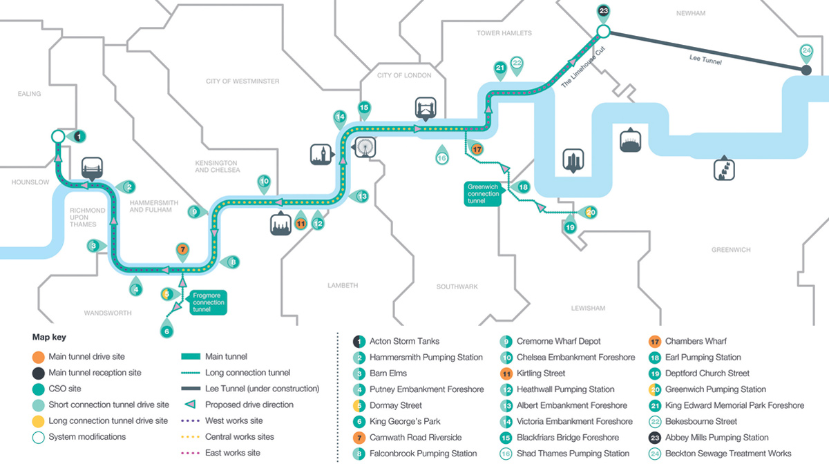
Thames Tideway Tunnel route map - West, Central and East sections - Courtesy of Tideway
London’s sewerage system was designed by Sir Joseph Bazalgette in the 1850s, for a population of four million people. While the Victorian sewers are still in excellent working condition, they are struggling to cope with the demands of the city’s growth. Every year, tens of millions of tonnes of raw sewage pour into the River Thames from combined sewage overflow (CSO) discharge points all along the river. In 2014, 62 million tonnes of untreated sewage spewed into the river from Chiswick in the west through to Greenwich in the east. The solution to this unacceptable, unsustainable situation is a tripartite one. Thames Water has delivered the first two components of the overall London Tideway Improvement Programmes, (i) the Lee Tunnel, tackling the single largest overflow point near the Olympic Stadium in Stratford and (ii) the expansion of the five sewage treatment works on the tidal River Thames. The final piece of the puzzle is the Thames Tideway Tunnel.
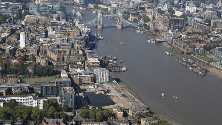
Chambers Wharf in Bermondsey is the main drive site – Courtesy of Tideway
Thames Tideway Tunnel
The Thames Tideway Tunnel – a 7.2m diameter interception and transfer tunnel running up to 65m below the river – will intercept and collect sewage from thirty-four of the most polluting CSO discharge points along the River Thames. Starting in west London, the route for the main tunnel largely follows the River Thames to Limehouse, where it continues north-east to Abbey Mills Pumping Station near Stratford. There it will connect to the Lee Tunnel to complete the transfer of sewage to Beckton STW.
The project has been split geographically into three main construction contracts, which correspond to the anticipated tunnelling conditions in the Central, East and West of the capital. Each section of the tunnel will be under construction at the same time to ensure that the Thames Tideway Tunnel can be completed effectively. This paper looks at the technical challenges of East section.
Tideway East technical challenges
Tideway’s East section is the deepest part of the project, reaching depths of 65m. Chambers Wharf in Bermondsey is the main drive site for this 5.5km section to Abbey Mills and the existing Lee Tunnel. The East development also includes a 5m internal diameter connection tunnel of around 4.5km running from Greenwich Pumping Station to the main tunnel at Chambers Wharf.
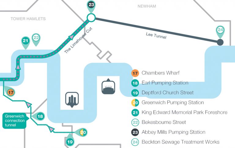
Tideway East route – Courtesy of Tideway
The joint venture (JV) constructing both tunnels under a £605m contract is Costain, Vinci Construction Grands Projets and Bachy Soletanche with designers Mott MacDonald.
Preparation is underway on site at Chambers Wharf for construction to begin on the work platform for the main East drive. This involves construction of a cofferdam in the Thames measuring 145m by 60m which will be filled with ballast. It will also allow for creation of a non-tidal berth to allow tunnel segments and tunnel ready mix concrete secondary lining aggregates to be brought in by river transport to reduce lorry movements. When the cofferdam is complete, construction can start on the shaft to create the launch pit for the TBM. This is going to be 60m deep, created using the hydrofraise method of diaphragm walling.
Here, we look at some of the key engineering challenges facing the East team as they move into the construction phase of the project.
Maintaining CSO flows and sewer flows during interception
On the Tideway East section, four of the five major work sites require flows to be maintained through existing sewers during the interception works, or for the CSO discharge to be maintained while building the new shaft and interception structure in the foreshore. During the next few months, a complex sequence of construction works to build new infrastructure around existing sewers will be developed whilst maintaining flows and progressively connecting the new system into the old.
One example is at King Edward Memorial Park Foreshore (see schematic below) where a new flap-valved outfall (1), new penstocks to isolate shaft and tunnel (2) and new interception structure (3) will be built in the river Thames within a temporary works cofferdam (4). This will mean the use of precast technology and phased construction to transfer the flows from the CSO outfall through the new structure once complete. The challenge is the existing river wall through which the CSO discharges cannot be loaded or significantly affected by any temporary works needed to build the connection.
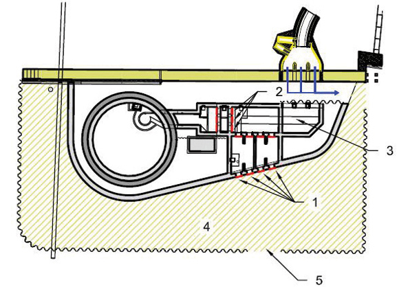
King Edward Memorial Park foreshore – Courtesy of Tideway
At the Earl and Greenwich Pumping Stations the sewers will have to be maintained throughout and interception structures built around existing assets.
For the Deptford Church Street site the challenge is to build an interception chamber around a live sewer which is currently under a red route dual carriageway. In order to avoid closing the road for a significant period, options under consideration include installation of a temporary road bridge or a pipejack or heading to intercept.
Predicting settlement and movement associated with the works
Excavating the Tideway tunnels, shafts, chambers and constructing new foreshores could lead to ground movement both at the surface and below ground. The level of any movement will depend on a number of factors including the depth and volume of work below ground, soil and groundwater conditions and the presence and nature of building foundations or third party assets.
For preliminary greenfield assessment purposes, a parabolic ground settlement distribution as proposed by New and Bowers (1994) has initially been adopted for the Thames Tideway Tunnel. It incorporates a diameter dependence based on the finite element sensitivity analysis undertaken on the Crossrail Project. The magnitude of settlement predicted by this is greater than we believe will happen in practice.
Revised parabolic shaft settlement distribution based on analysis of the Lee Tunnel Shaft F case history presented by two papers (Schwamb et al: Fibre Optic Monitoring of a Deep Circular Excavation Geotechnical Engineering 167 No 2 144-154 2013 and Schwamb & Soga: Numerical Modelling of a Deep Circular Excavation at Abbey Mills in London Geotechnique 2015) will be used to predict the settlements associated with the five deep shafts.
As a result, the extent of third party properties expected to be impacted by the works will be significantly reduced, compared to the initial number highlighted in Tideway’s initial and appropriately conservative assessments during the Development Consent Order process.
The project aims to gather further data, on the movements and settlements associated with deep excavation construction in urban areas, for future projects.
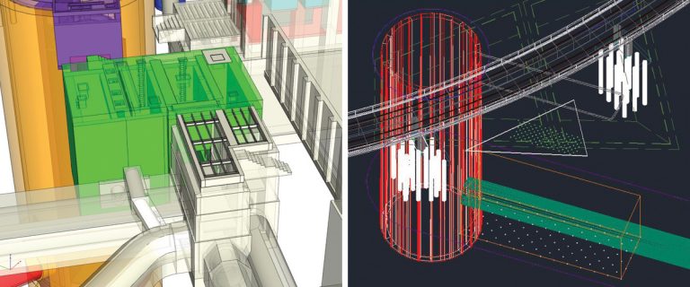
(left) Secant piled cofferdam at Greenwich Pumping Station and (right) CAD model for Greenwich Pumping Station shaft – Courtesy of Tideway
Minimising ground movements affecting listed Greenwich PS
At Greenwich Pumping Station, planned work is in the vicinity of three Grade 2 listed buildings comprising the Pumping Station, the former coal sheds and the Network Rail viaduct.
In particular, an excavation deeper than 10m is necessary to construct the new interception chamber adjacent to an existing penstock chamber near the pumping station building.
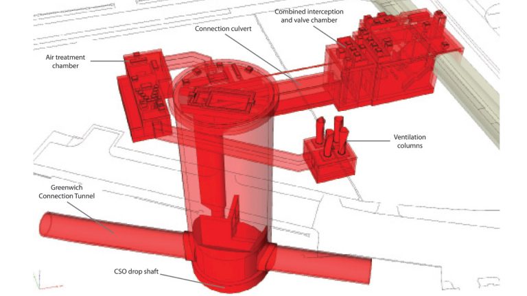
Greenwich Pumping Station interception – Courtesy of Tideway
In order to minimise ground movements potentially affecting these structures, the new chamber will be built within a secant piled cofferdam using a top down sequence where grids of stiff concrete beams will be built at different levels as the excavation progresses.
This required an adjustment of the chamber design to accommodate the presence of these walling and propping concrete structures without affecting hydraulic and operational requirements.
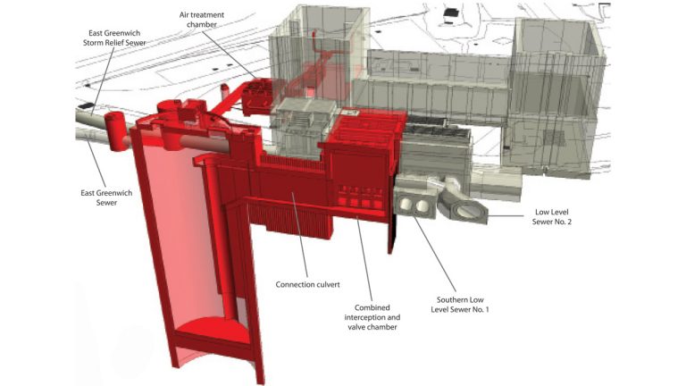
Greenwich Pumping Station interception – Courtesy of Tideway
Addressing contamination at Earl Pumping Station
At Earl Pumping Station the site is impacted by typical gasworks-derived contamination from adjacent historic offsite uses since the 1870s, namely asphalt and naptha works (partially onsite and to the south); tar works (to the south); and a timber yard (to the east). Due to the ground conditions at site there are no impermeable geological barriers to prevent the dragging down of contamination into the Chalk Aquifer during the works. At present, the contamination sits in the River Terrace Gravels and Thanet Sands above the Chalk.
A number of aspects will therefore need to be assessed and managed, including the methodology for sinking the shaft through the contaminated ground into the chalk. Currently, the proposal is for a soil mixed curtain wall within which a diaphragm wall is sunk. The project also needs to take into account the management of groundwater without the use of active dewatering, which risks drawing contamination into the site, in addition to considerations for the protection of the workforce and adjacent third parties from vapours or contaminated waters and odour.
It is vital to explore the potential for remediation works in advance and to prevent contamination entering the permanent works during its 120 year design life.
Consideration is being given to soil vapour extraction methods, use of specially enclosed skips to directly transfer material from an excavation straight off site, and remote controlled plant to avoid people entering the excavations. This is just a part of the transformational health and safety approach to the Tideway Tunnel project.
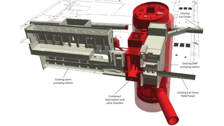
Earl Pumping Station interception – Courtesy of Tideway
Shaft internal structures
In the east sites, where the ground is predominantly chalk, the shafts will drop straight into the main tunnel instead of into a connection tunnel. This led to the need for a unique solution – the creation of vortex drop shafts within on-line shafts – which takes away much of the energy of large volumes of falling water, preventing damage at the bottom of the shaft and ensuring air is not entrained in the tunnel. This will involve the use of complex formwork and falsework in the shaft.
BIM
The project will be one of the first in the UK to truly use building information modelling for the development of the design, 4D programme planning, MEICA and civils works interaction. It is enabling design teams across multiple organisations and countries to work on an integrated design without the need to produce abortive drawings to communicate.
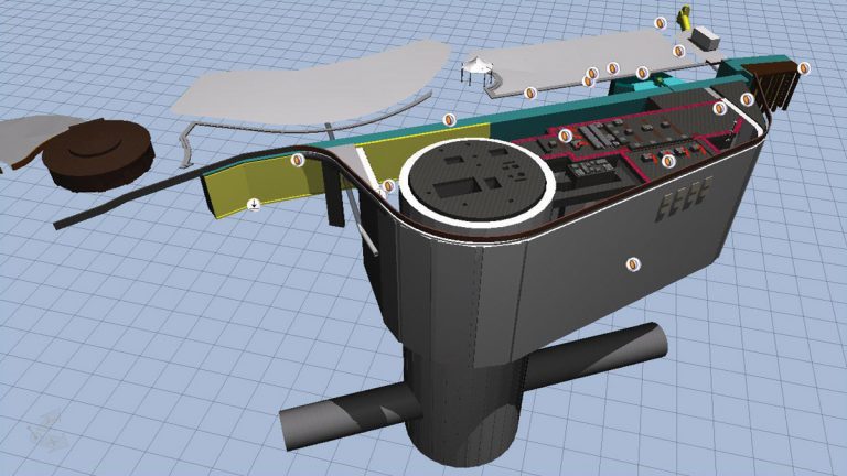
BIM model viewed in Bentley Navigator – King Edward Memorial Park foreshore – Courtesy of Tideway
The BIM model will also be combined with 3D virtual reality software for inductions, safety briefings, OPMAN and task briefings. SMART boards are also being used for communication between designers and the site team in terms of drawing mark-ups and changes.
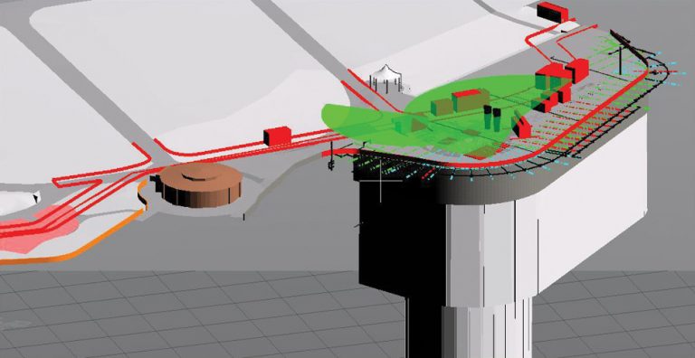
BIM model viewed in Bentley View – King Edward Memorial Park foreshore – Courtesy of Tideway
TBM launch via sprayed concrete lined chalk adits
The East team is proposing to launch the TBM launch from adits in the chalk constructed using sprayed concrete lining (SCL) within a grouted chalk block. The challenge is to create large underground caverns in the chalk which is of good CIRIA C574 ‘A grade’ but which will be under high water pressure.
Grouting using vertical and inclined holes to intercept fissures is planned from the surface, with the use of microfine cements if required to target a permeability of 1 x 10⁻⁷m/s. A toolbox of measures will be in place during the SCL excavation to support the excavation and manage the water which may be trapped as a result of the grouting.
Progress and schedule
Following the removal of 20,000 tonne stockpile from the Chambers Wharf site in June, work started on extending the site into the river to allow for construction of a main drive shaft, due to start in early 2017. The main tunnel TBM is expected to arrive in 2018, with tunnelling due to start later that year.
Completion of the main tunnel and its connection to the Lee Tunnel at Abbey Mills is scheduled for 2023, but Tideway is working towards reducing this by 12-18 months. Meanwhile, work on the Greenwich connection tunnel will begin in Autumn 2016 and is due to finish in 2023.


