Tideway Central – Albert Embankment Foreshore (2020)
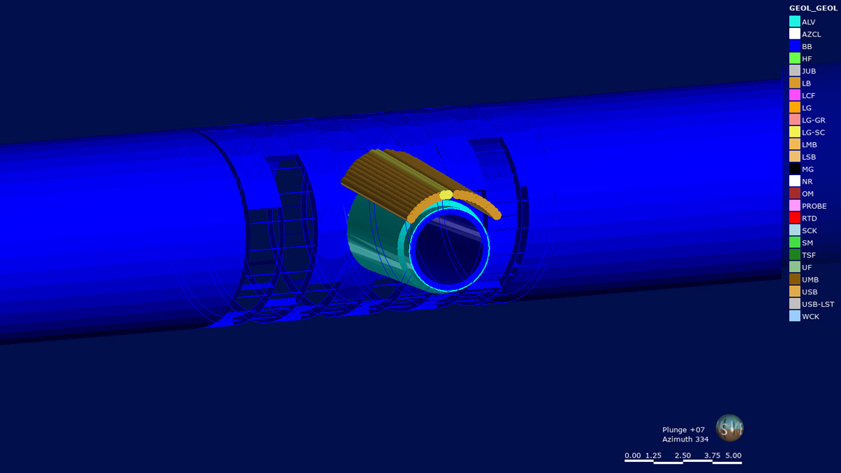
Pipe canopy above connection tunnel - Courtesy of FLO Geotechnical team using Leapfrog Works GeoModelling software
The Thames Tideway Tunnel is a major tunnelling project designed to mitigate the large-scale pollution problem involving the discharge of sewage into the River Thames. The project consists of a 25km long TBM tunnel under the river along with numerous shafts, culverts and connections tunnels constructed using sprayed concrete lined techniques. These will be used to divert sewage flows from the existing network to an upgraded treatment plant in Beckton STW in east London. This report focuses on the Albert Embankment Foreshore (ALBEF) site, where the structures will intercept and divert flows from the Clapham and Brixton storm relief CSOs located in the Albert Embankment river wall on the foreshore of the tidal Thames.
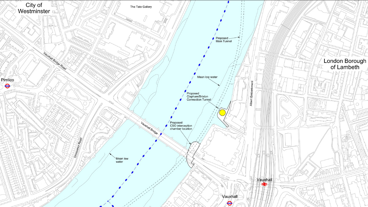
Albert Embankment Foreshore site location plan – Courtesy of AECOM
Background
Flows will be transferred through connection culverts under the foreshore to new foreshore structures. There are two main proposed foreshore structures:
- The interception chamber which combines flows from the Clapham and Brixton storm relief CSOs and accommodates a new CSO outfall.
- Approximately 100m downstream, another foreshore structure accommodates air management facilities and a CSO drop shaft of 16m in diameter to convey the flows to the main tunnel. Just above the base of the CSO drop shaft a connection tunnel will be constructed from the shaft lining to the main TBM tunnel to convey the flows. This connection tunnel will be constructed within the granular Lambeth Group soils which poses a significant geohazard to the works.
This report will review the geotechnical hazards that posed a risk to the construction of the tunnel and the engineering application of ground modelling utilising multiple sources. Once the hazards were reviewed a design was compiled for the proposed measure of a pipe arch above the tunnel crown to help mitigate the risks associated with the granular material in a tunnel crown, thus implementing a solution to a potentially large scale engineering problem.
Key objectives
When undertaking a project involving sprayed concrete lined (SCL) tunnels adjacent to highly sensitive assets under the heavily trafficked River Thames, understanding the ground conditions and risks associated are imperative. The key objectives of this report will be to:
- Identify the risks associated with the construction works.
- Create an accurate and representative 3D model of the ground to better understand and visualise those risks.
- Propose a viable mitigation measure to limit those risks.
- Follow the design process from ‘Design Brief’ through to CAT III check of the proposed mitigation measure.
- Construct and implement the mitigation measure.
- Verify ground treatment measure has been implemented effectively during tunnel construction.
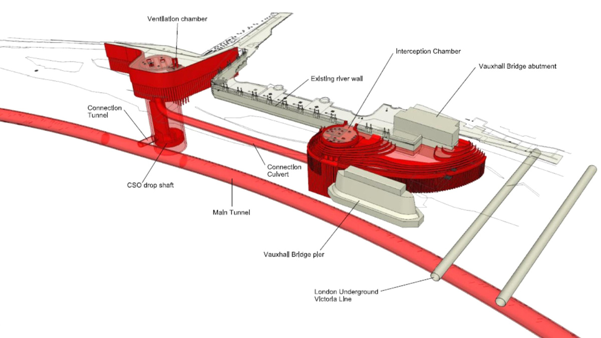
3D view of proposed and existing structures – Courtesy of AECOM
Thames Tideway Tunnel: Albert Embankment Foreshore: Supply chain – key participants
- Principal contractor: Ferrovial/Laing O’Rourke Joint Venture (FLO JV)
- Pipe canopy drilling and grouting sub-contractor: SITE Ltd
- Pipe canopy designer: OTB
- SCL designer: COWI and AECOM
- CAT III checker: Dr Sauer
- Dewatering sub-contractor: WJ Groundwater
- Piling: Ivor King The Piling People
Challenges encountered
The variable nature of the ground conditions posed a serious risk with the potential for settlement of some very sensitive assets. In addition to this, the risks associated with working under the River Thames meant high profile challenges were along the way. This report will demonstrate how a technical solution was devised utilising geotechnical engineering principles to assess the ground conditions ahead of tunnel excavation and how this information is then used to solve engineering problems during the design and construction phase.
There are many issues associated with tunnelling through the Lambeth Group; the following main areas will be reviewed in this report:
- Water ingress into the tunnel face during construction from water bearing sand channels causing instability.
- The risk of ground gas ingress and the possibility of a hypoxic atmosphere in the tunnel.
- Ground modelling assessment during tunnelling and limitations of the techniques used.
The main practical examples that will be used to demonstrate the above will be the design and implementation of a pipe canopy above the tunnel crown prior to commencing the drive. This is intended to stabilise any unfavourable ground conditions that might be encountered. The risks associated with the ground gas encountered at surface will be managed through the continuous purging and monitoring of the surface dewatering wells.
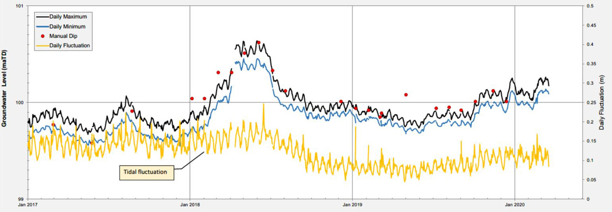
Upper aquifer water levels – Courtesy of AECOM
SCL groundwater risk
The principal ground hazard concerning the adaptation of open SCL tunnelling techniques is the potential presence of water bearing sand layers within the Harwich Formation and Lambeth Group potentially within the tunnel face, the Thanet Sands below the tunnel invert and the River Terrace Deposits above the tunnel crown. If the groundwater pressures within the granular strata comprise a significant proportion of the face, then direct face instability can occur. This could result in overbreak and increased settlement of the tunnel and/or the structures above at ground level. In addition, groundwater ingress can result in poor and unsafe working conditions. It should also be noted that a wet substrate hinders the adherence of sprayed concrete to the face, potentially prolonging the period to face closure.

Intermediate aquifer water levels – Courtesy of AECOM
Ground conditions
The ground conditions are quite varied along the path of the tidal River Thames. The levels of the strata to be encountered was inferred from historic and recent ground investigation along with the piling records from when the shafts and other structures were being constructed. The units of the London Clay encountered across the site varied with levels of the claystone bands changing along the alignment. The underlying Lambeth Group posed the higher risk with the variable nature of the historic sand channels encountered in the ground investigation boreholes. The design of the tunnels and toolbox measures to counter any water ingress had to be continually re-assessed to ensure a safe and stable tunnel was being constructed at all times. The in-tunnel monitoring and convergence data had to be compared to the surface data to ensure any possibility of subsidence at the surface was identified early and mitigated.
One of the main areas of the concern was the presence of a water bearing sand channel above the crown of the connection tunnel which continues across to the main TBM tunnel junction as shown in the figure below.
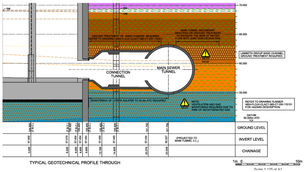
Albert Embankment site geotechnical cross section – Courtesy of AECOM
The water pressure in this sand channel was monitored using a specially fabricated piezometer which was installed through the grout ports of the TBM tunnel concrete segments. This groundwater information showed a significant pressure in the sand channel, which could pose a significant stability and health and safety risk for the connection tunnel drive and the TBM tunnel to which it connects. Any instability in the TBM segment rings would result in a serious health and safety risk for the TBM workers. Hence, it was imperative that any early signs of movement in the tunnel was noted and dealt with immediately.
Potential ground gas
Prior to any tunnelling works commencing, dewatering wells were installed at the surface to bring the local groundwater level down to that specified by the designers. The dewatering system at the Albert site consisted of 5 (No.) Chalk wells, 6 (No.) Thanet Sand wells and 4 (No.) Lambeth Group wells. Whilst testing the wells, it was discovered that a significant amount of ground gas was being emitted from both the Lambeth Group and Thanet Sand wells.
Ground gas has previously been noted in the London area in papers by Newman in 2013 and on other prominent construction sites. It is thought to be caused by historical abstraction from the Lower Chalk and Thanet Sand aquifer creating a cone of depression within the London area which allowed the Chalk to become unconfined and thus air entered the overlying strata which overtime became trapped and pressurised as abstraction reduced and the water levels recovered. The gas encountered in the surface wells were tested and confirmed to be completely depleted of oxygen. Thus, if this was encountered in a tunnel setting it would create a hypoxic atmosphere which would be a significant health and safety risk to the workforce.
Design and implementation of the pipe canopy
Once the need for a ground treatment solution had been identified by assessing the above risks, an ‘Engineering Design Brief’ was compiled by the contractor to identify the requirements to be met by the permanent works designers. The design brief set out the requirements the design needed to fulfill with respect to the stability risks associated with the granular layers above the tunnel crown:
- Ground treatment of the Lambeth Group Sand to be undertaken to achieve the required geotechnical parameters.
- Minimum strength: Cu = 300kN/m2 | Minimum stiffness: Eu = 150MN/m2 | Maximum permeability: K = 1e-7m/s.
- Method statement for the ground treatment.
- Minimum width of 6.0m from the front and 4.0m from the side of the excavation surface.
The design was undertaken by OTB and the CAT III check was subsequently completed by Dr. Sauer. The check highlighted a number of useful points pertaining to the design including the dewatering design and how that will impact the stability of the sand layer. The SCL procedure and experience of the team was taken into account to ensure the construction of the ground support and the subsequent tunnel drive was adequately resourced.
The drawing below shows the final design for the pipe canopy above the connection tunnel. It was important to note the pattern and geometry of the near horizontal pipes to be drilled to ensure sufficient coverage above the tunnel crown.
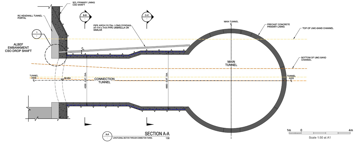
Pipe canopy design – Courtesy of OTB
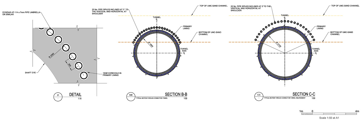
Pipe canopy design – Courtesy of OTB
The design set out 23 (No.) pipe spiles to be installed at 3° inclines 10.7m in length at 200mm centers. This was undertaken using Comacchio MC800 drill rig. The drill rig was set out to a high degree of accuracy utilising a reference line from the other side of the shaft to ensure the correct inclination and azimuth were used. The arisings from the borehole were logged and once the drill rods were retracted a steel pipe of the same diameter and length was installed. These were then grouted to provide support medium.
As-builts of the pipes were taken after drilling and plotted on to a 3D geological model to ensure the correct coverage. Once all pipes were installed the tunnelling drive was commenced. The drive consisted of 2 sections – the connection tunnel consisted of 5 (No.) 1m advances at the smaller diameter of 3.5m. The main tunnel junction consisted to an enlarged diameter of 4.86m which was a further 3.675m to the main tunnel. The whole drive consisted of a total of 9 (No.) advances.
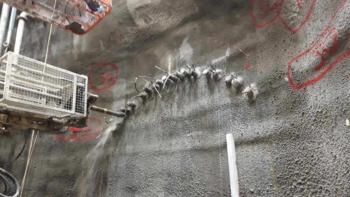
Water flush drilling of pipe canopy – Courtesy of FLO
Conclusions and lessons learnt
The successful ground treatment solution implemented for the connection tunnel drive was evidenced by the completion of the tunnel with no ground related issues encountered during construction. The dewatering took effect throughout the drive and the pipe canopy provided the support in the crown which ensured no collapses or fall-outs due to ground conditions throughout.
The main lessons learnt throughout the construction of this drive was that a robust design and CAT III check ensured that when it came time to construct the pipe canopy and undertake the tunnelling drive no surprises were met.


