
Tunbridge Wells South WwTW (2026)
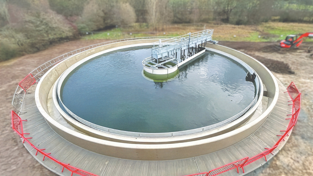
Final settlement tank 4: Hydrostatic test - Courtesy of CMDP+
Southern Water’s (SW) Tunbridge Wells South Wastewater Treatment Works (WwTW) in Kent serves the southern part of the Royal Tunbridge Wells catchment, which has a population equivalent (PE) of 30,348. An upgrade project was required to improve the quality of treated water returned to the environment and ensure compliance with the new environmental standards set by the Environment Agency under the Water Industry National Environment Programme (WINEP3). The project commenced on site in March 2024, and the main works were completed in February 2026.
Existing works
The existing facility comprises an inlet works area (including grit removal, inlet screens, and a storm overflow weir leading to two storm tanks), which feeds into the primary settlement distribution chamber, where the flow is dosed with ferric to remove phosphorus. The flow then proceeds to two radial primary settlement tanks.
Settled sewage flows to an anoxic tank, where it combines with return activated sludge (RAS) before entering the aeration lanes. The aeration lanes are aerated via fine bubble diffusers. The biologically treated effluent and mixed liquor then pass to three final settlement tanks (FSTs). RAS and surplus activated sludge (SAS) are withdrawn from the tanks and lifted by two Archimedes screw pumps back to the anoxic tank, with part of the RAS wasted as SAS.
FST effluent gravitates to the sand filter feed pumping station, where it is pumped by three sand filter feed pumps to the deep bed sand filters. Sand filter effluent gravitates to the final effluent chamber before being discharged from the site to River Grom, a tributary of the River Medway upstream of Tunbridge.
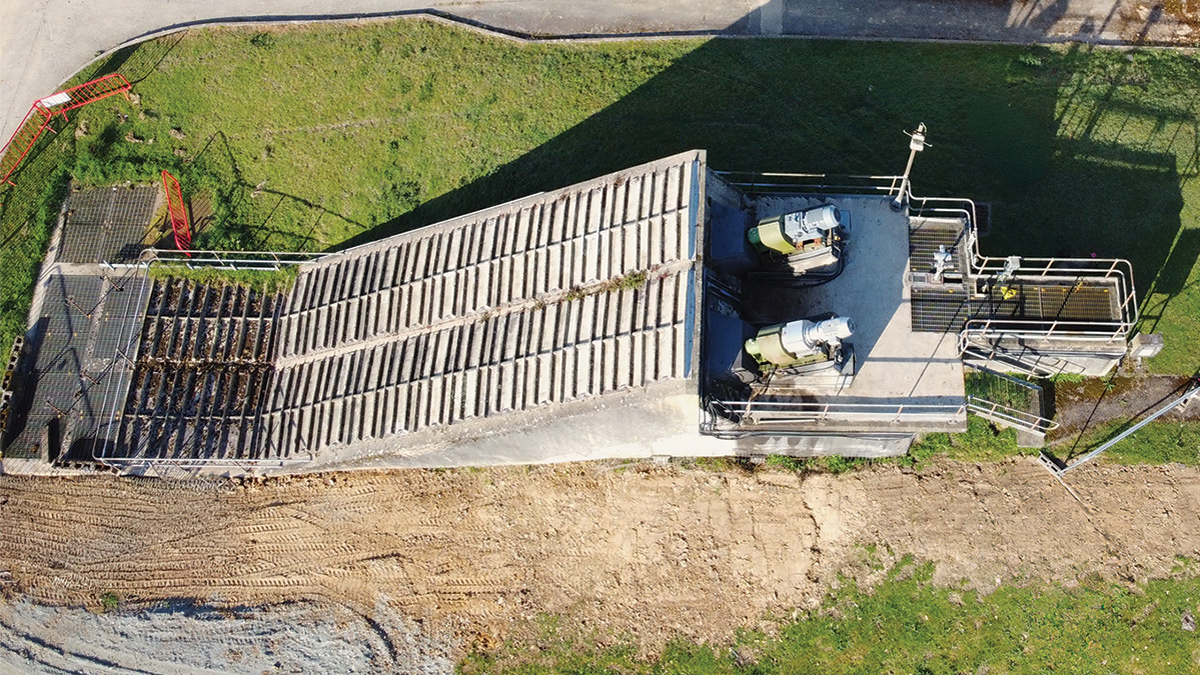
RAS pumping station area – Courtesy of CMDP+
Project drivers
The £10.2m Tunbridge Wells South WwTW upgrade scheme was required to meet a range of regulatory, environmental and operational requirements, including the following drivers:
- WINEP: P removal (regulatory date: 22 December 2024).
- U_IMP5 Programme: Increased flows (regulatory date: 31 March 2025).
- U_MON3/4 Programme: Upgrade of monitoring equipment (regulatory date: 31 December 2026).
Project delivery
The Tunbridge Wells South WwTW Upgrade was delivered by CMDP+, a joint venture between Costain and MWH Treatment. As one of Southern Water’s Delivery Partners for its AMP6, AMP7 and AMP8 Capital Investment programmes, CMDP+ has delivered, and continues to deliver, a range of schemes to maintain and improve Southern Water’s water supply and wastewater treatment works.
CMDP+ followed the process solution, as determined by the Client, to meet their needs. On-site works included upgrades to the ferric dosing system and the installation of a new sodium hydroxide dosing system, upgrades to the inlet area, and the installation and commissioning of a new RAS pump and a fourth FST.
The upgrade works at Tunbridge Wells South WwTW were undertaken within a live wastewater treatment facility, requiring precise planning to integrate with existing assets and maintain full operational continuity.
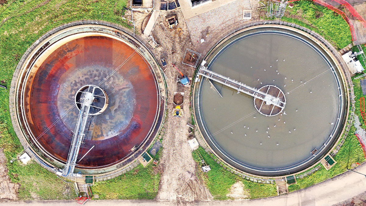
PST scraper bridge refurbishment works – Courtesy of CMDP+
Tunbridge Wells WwTW: Supply chain – key participants
- Client: Southern Water
- Principal designer & contractor: CMDP+ (Costain/MWH Treatment Joint Venture)
- Designers: Ferntec Ltd
- Civil engineering contractor: Coleman Construction & Utilities
- Piling contractor: Roger Bullivant Ltd
- Formwork: DOKA
- Mechanical contractor: Pipe Systems Ltd
- Electrical contractor (P scope): Econotech Ltd
- Electrical contractor (U_IMP5 and U_MON3/4 scope): Linton Electrical Contractors
- LVA/systems integration: MCS Control Systems
- Chemical dosing (ferric): Lintott Control Systems
- Chemical dosing (caustic): Bridges Electrical Engineers Ltd
- Scraper bridges: Jacopa
- Flow meters: Siemens
- Pumps: Xylem Water Solutions
Project scope
Phosphorus removal
New assets were required to meet the revised permit conditions (phosphorus standard of 0.3mg/l (mean), Fe: 4mg/l (95%) 8mg/l (U/T)) as identified in the Water Framework Directive (WFD) IMPg-P driver in the Water Industry National Environment Programme (WINEP3).
The project included the upgrade of the existing 30m³ ferric dosing facility and the provision of a second dosing location. Ferric dosing is applied at two points within the treatment process:
- At the new primary settlement tank distribution chamber.
- At the aeration lanes outlet distribution chamber leading to the final settlement tank distribution chamber.
A new 40m³ sodium hydroxide (caustic) dosing facility was also installed, with a single point of application at the anoxic channel upstream of the biological treatment stage. In addition, a new low-voltage assembly and control panel was provided to support the new chemical dosing systems.
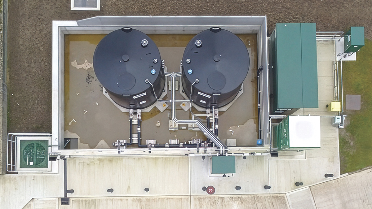
Aerial view of sodium hydroxide bund area – Courtesy of CMDP+
U_IMP5
To increase the full flow to treatment (FFT) from 260 l/s to 321 l/s, new process assets had to be installed to provide additional treatment capacity and accommodate projected population growth to the design horizon of 2035.
To address the U_IMP5 driver, the project included modifications to the inlet works and primary settlement tank (PST) distribution arrangements to enable the future full flow to treatment (FFT) to be passed forward. These works comprised a new flow diversion manhole, a new MCERTS-certified FFT flow meter, and a new PST distribution chamber. A PST bypass facility was also provided, together with the replacement of the existing PST scraper bridges.
Additional secondary settlement capacity was delivered through the construction of a new 22.5m diameter radial FST equipped with a half-bridge scraper. The RAS pumping station was upgraded with a new submersible RAS pump, while the tertiary treatment feed pumping station was modified to accommodate future FFT and return flows through the upsizing of the existing pump impellers.
U_MON3/4
To meet the requirements of the U_MON3 driver, the existing Event Duration Monitoring (EDM) equipment on the site overflows was upgraded to an MCERTS-approved system. This provided confidence that full flow to treatment (FFT) compliance could be accurately monitored and demonstrated.
To comply with the U_MON4 requirement, the existing FFT ultrasonic sensor was replaced with an MCERTS-approved flow meter. The new flow meter provides accurate measurement and recording of FFT, enabling verification that the permitted FFT setting is maintained when storm tank overflows are in operation.
Other works
In addition to the process improvements, the project included a site-wide upgrade of the telemetry system, providing enhanced operational monitoring and control capabilities across the treatment works.
Inlet area works
As part of the upgrade to enable future FFT and its measurement and monitoring, a new inlet works area was constructed adjacent to the existing inlet channel, with channel- and wall-mounted penstocks to divert flow to the new assets. The new inlet works area includes a flow diversion manhole, which leads to the FFT MCERT flow meter and then into a PST distribution chamber. The existing PSTs were also refurbished, with the scraper bridges replaced and the internal ancillaries renewed.
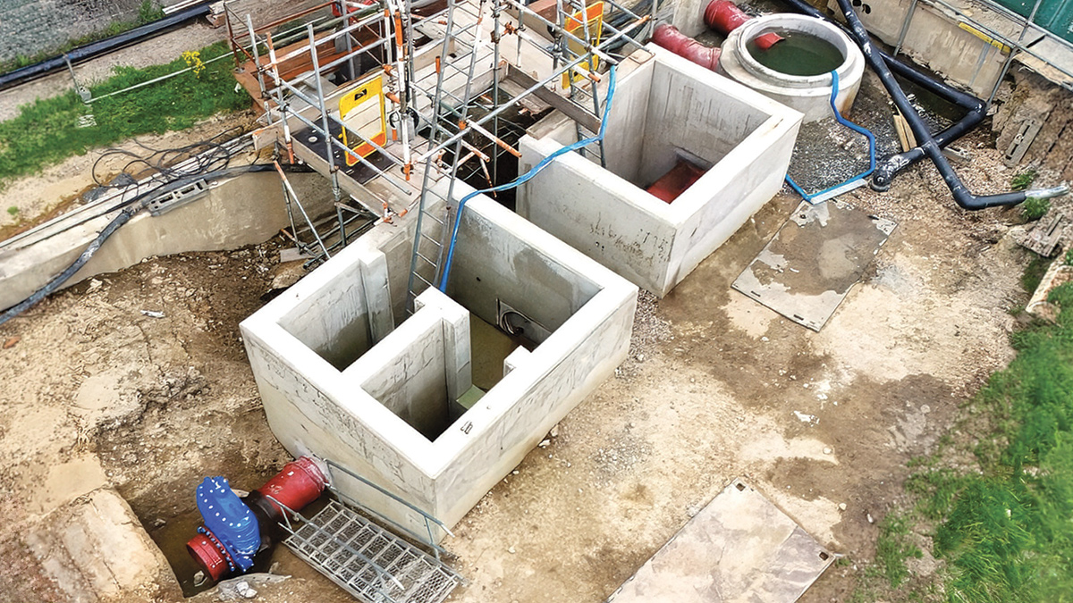
Construction of inlet upgrade – Courtesy of CMDP+
Safe Control of Operations (SCOs) is a system of approval for planned work with a direct impact on the existing treatment process, helping to mitigate risks that could affect site compliance.
A key challenge with this construction was the need for periods of low flow to carry out coring into the inlet channel under an SCO, enabling the pipework required to connect the new assets to be installed. As a result, the work could only be carried out in the summer, meaning the original sequence of the works could not be achieved.
In addition, the new pipework connection to the existing PSTs had to cross existing live pipework, adding further complexity to the installation. The PST refurbishment works also meant that one of the tanks needed to be isolated while the works were carried out, with all flows diverted to the other PST during this period.
The revised sequence of works was carefully planned through close coordination with the Southern Water team throughout these SCOs, ensuring that the SCOs were carried out successfully.
Additional RAS pump
A new submersible pump was installed at the RAS Pumping Station, along with a new flowmeter and a pipeline to the anoxic tank.
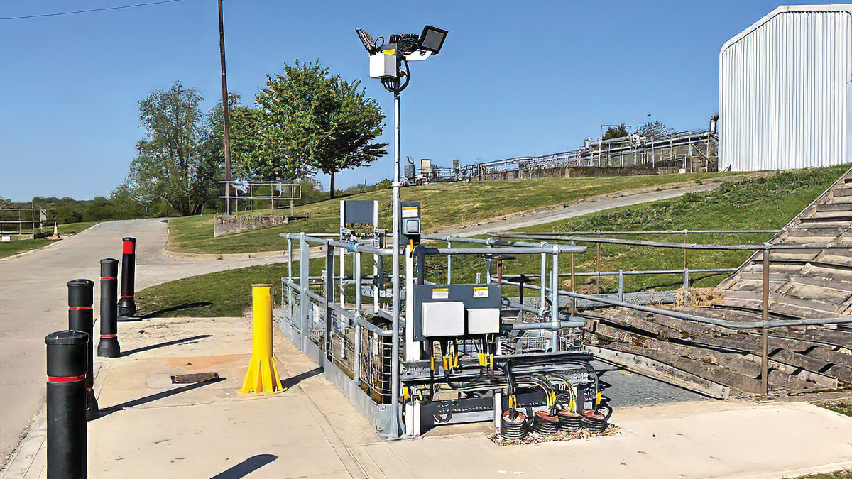
RAS Pumping Station – Courtesy of CMDP+
Following reviews with the site construction and design teams, the design was modified to improve the safety and accessibility of pump removal for maintenance. Instead of providing a cut-out in the flooring, which would have introduced the risk of a fall from height, it was decided to modify the existing wet well design by removing the flooring entirely and installing a handrail around the edge. This meant that operators accessing the pumping station would not need to stand adjacent to an open section of flooring.
Sodium hydroxide (caustic) dosing facility
A new sodium hydroxide storage bund and associated dosing units were installed as part of the upgrade.
Because the bund was adjacent to an underground pumping station building, piles had to be installed beneath the base of the sodium hydroxide bund structure. These were installed by Roger Bullivant before the base of the structure was constructed. The caustic bund construction required close coordination through CMDP+ among the civil, mechanical and electrical contractors to ensure continuity of work, with resource scheduling carefully managed.
New final settlement tank
The largest structure constructed as part of these upgrade works was the new 22.5m diameter radial final settlement tank with a half-bridge scraper.
Firstly, an existing pumped rising main crossing the construction area had to be diverted under an SCO. This required shutting down two pumping stations outside the site. Customer interaction and liaison were required, alongside coordination with the SW team, to ensure these works did not impact the wider network.
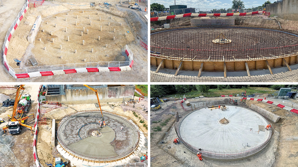
Final settlement tank 4: (top left) works area piling, (top right) base and wall reinforcement steel installation, (bottom left) base concrete pour, and (bottom right) reinforcement installation – Courtesy of CMDP+
The area was then prepared with a temporary piling platform for a 21T piling rig. This platform was later redesigned and topped up to allow a 60T crawler crane to operate safely throughout the rest of the construction. A total of 39 piles were installed for the FST base. The pipework for the FST was then installed, and the piles were exposed and cropped.
The base for the FST was then constructed, with around 12T of steel reinforcement installed. The concrete pour for the base required 28 concrete wagons and was carried out in one day. This required careful traffic management due to the narrow access road into the site and to prevent disruption to the local community.
The FST walls had reinforcement that overhung due to the shape of the launder channel. This required a temporary works design incorporating additional reinforcement bars to strengthen the arrangement and prevent deformation while the steel fixers worked.
Due to the launder channel’s unusual shape and the circular nature of the FST, an innovative DOKA formwork system was used to complete the pours. The formwork was fabricated to the design radius at DOKA’s facility. This significantly improved efficiency on the project by reducing the labour required to fabricate the formwork on site.
The formwork arrived as a set of 10 external and 10 internal panels, which were lifted into place with a 60T crawler crane. The panels were fully prefabricated and came with integrated connections, propping equipment, and stopends, allowing installation in the same manner as a standard panel system. These were installed to cover a quarter of the FST circumference and were reused for each subsequent pour. The internal launder and weir walls formwork were also supplied by DOKA and were installed after the completion of the main wall section in each quarter, before the final concrete pours were undertaken.
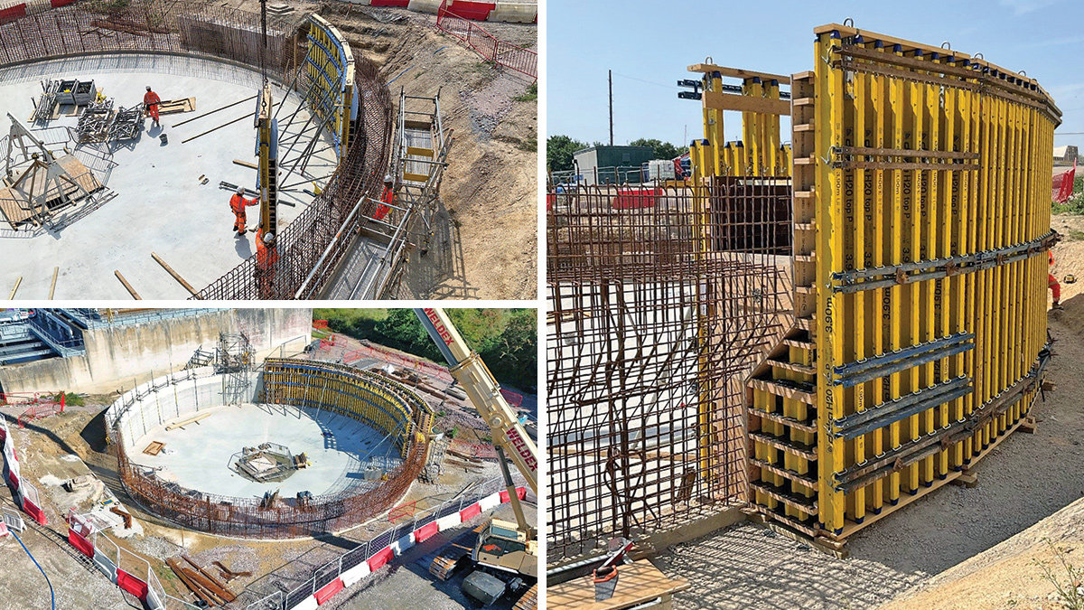
Installation of DOKA formwork on FST 4 – Courtesy of CMDP+
Conclusion
The £10.2m upgrade of Tunbridge Wells South WwTW has successfully delivered the improvements required to meet Southern Water’s environmental and regulatory obligations while enhancing the overall resilience and performance of the treatment works. The scheme provided new and upgraded assets to support phosphorus removal, increase treatment capacity, improve monitoring and compliance, and accommodate future operational requirements.
Throughout delivery, the project team actively sought opportunities to improve buildability, efficiency, and health and safety performance. Several innovative solutions were adopted to reduce construction risk and maximise value. These included redesigning the additional RAS pump installation to reduce the risk of working at height and prefabricating the DOKA formwork system at DOKA’s facility rather than on site, improving both safety and construction efficiency.
Construction commenced on site in March 2024, with the main works completed in February 2026.